

Page 1
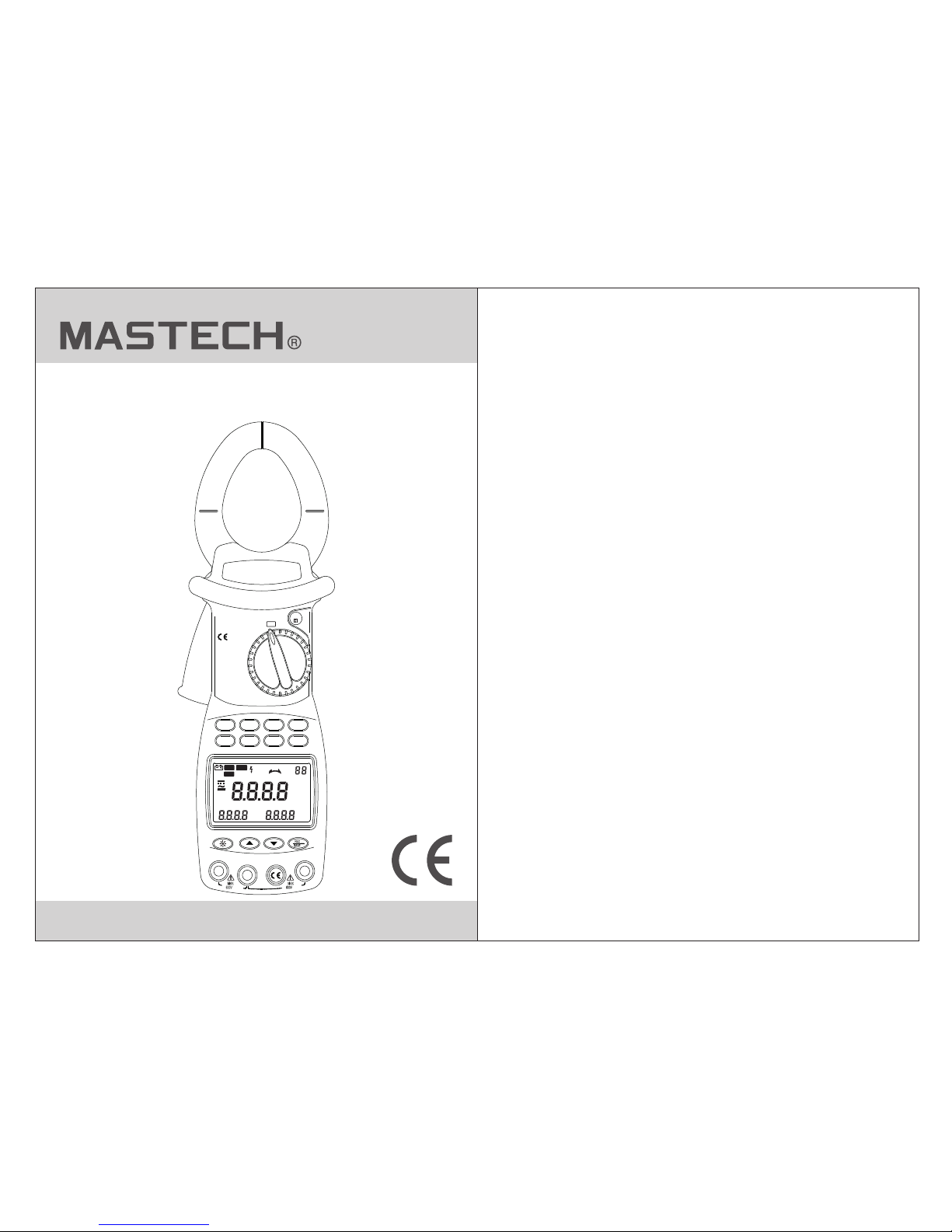
MS2205
DIGITAL CLAMP METER
OPERATION MANUAL
~
~
kW
1 PHASE
Ø
1 PHASE
kW/Ø
3 PHASE
HARM
A~
V~
HARM
°
APS
RS232
HOLD
REC
FS
LAG
LEAD
RST
CAL
USED
READ
MEMO
COSΦ
SINΦ
MAX MIN
VA
kWh
PEAK
%THD
kVA
Hz
HzA
PEAK
kWVAh
POWER CLAMP METER
MS2205
Yrue R MS
Harm onic
AUTO RA NGE
MODE I
U READ
CLEARRS232
Watt
SET
COM/V2
EN61010-1
600V CAT III
V3V1
HOLD
OFF
Page 2

CONTENTS CONTENTS
Safety Requirements...................1
Safety Instructions...........................2
Safety Sign........................................2
General Description.....................2
Features........................................3
Appearance...................................4
Knob Switch Operations...............6
B ................7utton Switch Operations
LCD Display.....................................10
I ..........................12nstruction Manual
T ............................21est Data Storage
Read Saved Data..............................22
RS232C Data Interface.....................22
Input Voltage and Current...............23
Backlight Display..............................23
..........................A ........ 23uto Power Off
D ......................24iagram of Safe Holding
Power curve diagram.............................25
Battery-low Indication............................26
Battery Replacement.......................26
General specification......................28
T ........................28echnical specification
Accessories ...........................................29
Page 3
01 02
Please caref ully read th e instruction man ual before
using the test er, and pay spe cial attention to “Warnin g”
content. Ple ase follow i nstructions und er “Warn ing”.
1. Please be ver y careful wh en test voltage is higher
than AC 30 V, and do ke ep in mind that your fi nger
shall not exce ed the hand- shielding part of the
test probe.
2. Do not measur e voltage wh ich is higher than th e
allowed inpu t limit.
3. Before use, p lease chec k the meter and test probe;
do not carry out testing in ca se the test probe is
naked, tester housing is d amaged, or there is no
LCD display, etc..
4. It meets requirements o f safety standards only when
the meter is used together w ith the supplied test
probes. In case the test pro be is damaged and
needs replac ement, it is r equired to replace it with
a test probe of the same model a nd identical
electrical s pecifica tions.
5. Please neve r carry out an y voltage measure ment
whenever the test probe is i nserted in any current
outlet.
Safety Instructions
Important sa fety signs ; please refer to
instructio n manual
High voltage h azard
Earthing
Double insul ation (Cat egory-II safety
equipment)
Battery low In dicator
The three-ph ase clamp- type digital powe r meter is
designed and m anufactu red in accordance w ith
internatio nal standa rd, IEC61010-1, a nd interna tional
safety speci fication , IEC1010-2-032 , and the mete r
strictly fol lows the saf ety standard of double-insu lation
AC 600 V CAT III.
6. Please do not e xpose the me ter to strong light, high
temperature, or dampne ss.
Warning
Before use, pl ease caref ully read this instruction
manual.Esp ecially sa fety contents!
Safety Sign
General Description
The 3-phase cl amp-type d igital power mete r is a handheld intelli gent harmo nic power tester, wi th both func tions
of digital cur rent testi ng and power testin g. Th e tester is
comprised of t hree chann els including vol tage, curr ent,
and power as wel l as a micro sin gle chip system, an d it is
equipped wit h a powerful s oftware for measu rement and
data process ing functi ons; it can measure, calculat e,
and display vo ltage, cur rent, active powe r, power fact or,
apparent pow er, passive p ower, frequency, harmo nic
parameters , with stabl e performance and o peration
convenienc e. Th e meter is esp ecially suitabl e for the
measuremen t and examin ation of on-site po wer
equipment an d power-su pplying circuit s; with hand -held
Safety Requirements
Page 4
03 04
clamp struct ure, small v olume, and light weight, it can
be easily carr ied by the use r, which makes it easy a nd
fast for doing m easureme nt. For measurement of singphase/thre e-phase po wer, The meter i s your ideal
choice
Features
1.The meter can b e used for tes ting power, voltag e,
current, peak value, pha se, frequency, power fa ctor,
phase angle, a nd reactio n factor, etc. of single-/
three-phas e circuit; a utomatic phase sequence
testing is possible for 3- phase measurement.
2. True effective va lue measur ement: accurate
measuremen t is possibl e even with serious
distortion i n current wa veform.
3. Low-consu mption hig h-speed single- chip
microproce ssor is empl oyed and sophisti cated
algorithm is a pplied, as a r esult, results can be
obtained rap idly and pre cisely, and up to 20
harmonics an d distorti on value thereof can be
measured.
4. It is equippe d with a large -size memory for saving
up to 100 groups o f test param eters.
5. It is equippe d with RS232 C communication a nd
recording in terface an d dedicated WINDOWS
graphics sof tware.
6. Hand-held , clamp-ty pe structure, with light weig ht,
convenient for carry-o n.
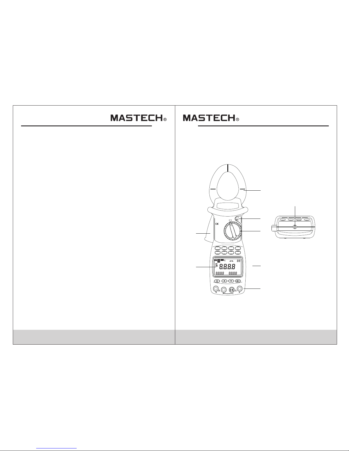
Appearance
kW
1 PHASE
Ø
1 PHASE
kW/Ø
3 PHASE
HARM
A~
V~
HARM
°
APS
RS232
HOLD
REC
FS
LAG
LEAD
RST
CAL
USED
READ
MEMO
COSΦ
SINΦ
MAX MIN
VA
kWh
PEAK
%THD
kVA
Hz
HzA
PEAK
kWVAh
POWER CLAMP METER
MS2205
Yrue RMS
Harmon ic
AUTO RAN GE
MODE I
U READ
CLEARRS232
Watt
SET
COM/V2
EN61010-1
600V CAT III
V3V1
HOLD
OFF
MAX~
600V
MAX
600V~
1
2
3
4
5
6
7
8
Page 5
Input termin al for measu ring the first
phase; use yel low test pro be for
connection .
Input termin al for measu ring the 2nd
phase; use bla ck test prob e for connection.
Common termi nal: groun d input terminal
(earthing) f or all measu ring functions; use
black test pro be for conne ction.
FunctionTerminal
V1
COM/V2
V3
Input termin al for measu ring the 3rd
phase; use gre en test prob e for
connection .
05 06
1. Current cla mp size: Φ 50 mm
2. HOLD button : DATA HOLD but ton; press d own
HOLD button, and the last re ading will be held an d
displayed on t he display, and “H OLD” symbol will be
shown; press H OLD button a gain, and the meter will
switch back to normal meas urement mode.
3. Function- switchin g knob :Rotation kn ob for selec ting
different measu ring funct ion
4. Function- selectio n button: Button for operatin g the
measuring fu nctions
5. Input termi nal
6. LCD display : 4-digit di gital display; 7- section LC D
for displayi ng measure ment operation function, te st
result, and un it sign.
7. Trigger :Pre ss down the tr igger, and the clamp w ill
open; releas e it, and the cl amp will close.
8. RS232C inte rface: Ded icated optical- electric al
interface wi re is used for o nline communication with
PC, as well as for r ecording d ata and data trend cu rve
in PC.
Knob Switch Operations
The function-sw itching kn ob is used for poweri ng-on and
for switchin g to any measu rement function in the
following ta ble.
For measurin g
active power, e tc.
For measurin g phase
angle, such as cos Φ
and sin Φ, etc.
For powering -offPowering-o ff po sition
Sign
Knob position
Functions
OFF
Active power p osition
(1 phase)
Single-pha se/phase angle Test p osition
For measurin g 3phase appare nt power,
etc.
For measurin g
AC-current
harmonics, e tc.
For measurin g
AC-Voltage
harmonics, e tc.
AC-voltage
harmonics te st
position
AC-Current
harmonics te st
position
3-phase appa rent
power positi on
KW/Φ
(3 phase)
A
KW
Φ
(1 phase)
V
Note:
When the meter i s automati cally powered off, be su re to
switch the kno b to “OFF” pos ition; turn on the meter after
5 seconds.
Page 6
07 08
Button Switch Operations
Button descr iptions
Function-selection b utton
MODE :Test-mode s witching button
SN
1
2
3
4
SET SET button :
I Current test button :
WATT Power test swi tching but ton :
5 U Voltage test button :
6 READ Data-Reading bu tton :
7 RS232 RS232 C button :
8 CLEAR Clear memory butt on :
9 Backlight bu tton
10
Reverse-se arch butto n
11 Forward-se arch butto n
12 REC/SAVE Data recording & storage button
13 HOLD Hold butt on
The followin g function s can be realized thr ough butto n
operations :
WATT Button
Under test mod e, you can mea sure active power,
apparent pow er, power fac tor, and phase angle a nd
display the re sults on LCD b y pressing WATT button.
MODE Button
Under KW-test mod e, you can pre ss MODE button to
switch the dis play of acti ve power and passiv e power;
under A/V~ test mo de, you can switch th e display am ong
total harmon ic distort ion rate F, r, an d harmonic
percentage .
SET Button
Under test mod e, you can pre ss SET button and then
press and button to set the ra nge of curre nt and
voltage, and t hen press th is button again to return. This
button serve s as CONFIRM ATIO N button during sto rage
and deleting .
U Button
Under test mod e, you can pre ss this button to test
voltage of the p resent cir cuit, and display the measure d
voltage of the p resent cir cuit on display.
READ Button
Under HOLD mod e, you can pre ss this button to display
the stored dat a; press thi s button again to return.
I Button
Under test mod e, you can pre ss I button to measure
current of the p resent cir cuit and display the measured
current of the circuit by th e clamp on LCD.
RS232 Button
Under test mod e, you can pre ss RS232 button to transfer
the present te st result to P C through a dedicated
interface wi re supplie d for the meter so as to record/pri nt
data and data tr end graph.
Page 7

09 10
Before press ing RS232 bu tton for data transferring,
the supplied R S232C inte rface wire shall be
connected to R S232C inte rface socket of the meter
and PC COM port, b efore real izing communica tion
functions.
CLEAR Button
Under data-r eading mod e, you can press CLEA R
button and the n press SET butto n to clear the test dat a
which is store d in the meter u nder a specified nu mber.
Button
You can press button to tur n on or off the backlight.
After it is turned on for 20 sec onds, the backlight will
automatica lly be turne d off .
Button
Under VOLTAGE-RANGE- SETUP mode, you can
press button to changeth e voltage test range.
During testi ng harmoni cs, you can change th e times
of harmonics .
When reading t he saved dat a, you can press button
to search back ward thest ored data and show it o n
LCD. With ever y press of the b utton, the
searchingc ursor will m ove one step backwa rd to the
previous dat a.
Button
Under CURREN T-RANGE-S ETUP mode, you can
press button to change cur rent test range. During
testing harm onics, you c an change the times of
harmonics.
When reading t he saved dat a, you can press button
to search in the f orward dir ection the stored data and
show it on LCD. Wi th every pre ss of the button, the
searching cu rsor will mo ve one step forward t o the
next data
REC/SAVE Button
Under TE ST mo de, you can press REC /SAVE button to
display the ma x. /min. pow er, current, voltage that is
currently me asured; un der DATA HO LD mode, pre ss this
button to disp lay the stor ed number; press SET but ton
again to save th e held data in t he meter. Up to 100
groups of data c an be stored i n the meter.
HOLD Button
After measur ement, pre ss this button to hold this data on
LCD; after pow ering-off, da ta will display.
LCD Display
°
APS
RS2 32
HOL D
REC
FS
LAG
LEAD
RST
CAL
USED
READ
MEMO
COSΦ
SINΦ
MAX MIN
VA
kWh
PEAK
%THD
kVA
Hz
HzA
PEAK
kWVAh
Page 8

LCD symbol
Description
LCD symbol
Description
Data transfer
REC
Data
recording
Fast
F
Auto
powering-off
Data holding
Slow
S
Phase angle
lead
Phase angle
lag
LEAD
Battery power
indication
O
Phase angle
(degree)
Reversed
power factor
Power factor
3-phase
Normal
phase
RST
AC symbol Reversed
phase
Negative
symbol
Phase
lacking
MIN
Minimum
value
MAX
Maximum
value
Used
MEMO
Save
US ED
SINΦ
LAG
APS
RS232
COSФ
HOLD
Read
Voltage
Watt
Current
Frequency
Passive
power
VA
Apparent
power
PEAK
Peak value
Harmonic
percentage
High-voltage
warning sign
%
W
RE AD
VA r
V
A
Hz
11 12
LCD symbol
Description
LCD symbol
Description
Total harmonics distortion ratio
Total harmonics distortion ratio F
(relative to base wave)
Total harmonics distortion ratio r
(relative to real effective value)
H01r
H01F
%THD
Instruction Manual
AC voltage (V) measurement
ACV
Page 9

Switch
Inputting
terminal V1
Inputting
terminal V2
Inputting
terminal V3
Test object
V~
V1 socket
COM/ V2
socket
COM/ V2
socket
COM/ V2
socket
N/A
N/A
V3 socket
1-phase
2-phase
3-phase
13 14
1.According t o the connec tion mode as above Table ,
switch the fun ction swit ching knob to V~, select
correspond ing socket s from V1, V2, or V3 terminal,
and insert the t est wire.
2.Connect the t wo test prob es V1, V2 to the power
source or load t o be tested. The me ter will automati cally
test and displ ay the resul t, and the present harmonics
percentage w ill be shown o n the following lin e.
3.Under volta ge test mode , press SET button to show
”Auto V” and “Au to A” on LCD, and p ress to select a
proper volta ge range, an d then press SET to return .
4.Press MODE bu tton to show h armonics percentage
on LCD, and the to tal harmon ic distortion ratio F and R
will be cyclic ally displ ayed. Press / button to
display valu e of each meas urement of the harm onic.
5.When input vo ltage is gre ater than 50 V, “ ” sign
will be shown on L CD, prompt ing you to pay attent ion
to safety.
AC-current (A) measurement
NEUTRAL
3
2
1
V1 socket
V1 socket
Page 10

15 1 6
1.Switch the fu nction kno b to A~ position;
2.Pull the trig ger to open th e clamp, and then cli p a
wire which is to b e tested; th e measured current
value will be au tomatica lly shown on LCD
3.Press MODE bu tton to show h armonics percentage
on LCD, and the to tal harmon ic distortion ratio F and
r will be cyclic ally displ ayed.
4.Press ▲/▼ button to display v alue of each
measuremen t of the harmo nic.
If current of the wire being t ested is greater than
1000 A (R MS), ”OL” sy mbol will be displa yed instea d
of current value.
Note:
1.You can select 50/60-H z FIXED/AUTO frequen cy
test (AUTO). When i nput wavef orm fluctuates,
displayed ha rmonic val ues can be kept stabl e if
50/60-Hz FIXED mode is sel ected.
2. Under AUTO freque ncy test mod e, FFT calculation
is performed o nly when bas e-wave frequenc y is
between 45 and 6 5 Hz; harmon ic analysis is not
performed wh en base-wa ve frequency exce eds
this range.
Test of single-phase circuit
1.Clip the clam p on the test wi re of the power suppl y
or load. If the user needs to me asure a certain phase
of the 3-phase circuit, th en the clamp should clip on
the wire of the same phase.
2.switch the fu nction swi tching knob to KW position,
select corre sponding i nput sockets from V1 or V2
terminal and i nsert the te st wire.
3. After it is correctly conn ected, you can measure single phase power (a ctive powe r, power factor, appa rent
power, passiv e power, volt age, current, pha se angle,
peak value of vo ltage and cu rrent, and frequency):
4. The meter will car ry out autom atic measuremen t and
display acti ve power, and v oltage/curren t value of the
load being tes ted will be di splayed on the bott om line
of LCD; press down MODE butt on, Var value of
passive powe r will be disp layed on LCD; press WATT
button to display appare nt power and power fa ctor
(cos Φ); negative power fa ctor signifies that the load
being tested is a load with ca pacitor characteristics .
5. The maximum meas urement ra nge of active power k W
is 600 kW; if this range is exce eded, “OL” symbol will
be displayed b eyond this r ange. If voltage being
tested is greater than 600 V, or curren t being tested
greater than 1000 A, “OL” symbol will b e displaye d
on LCD.
°
APS
RS232
HOLD
REC
FS
LAG
LEAD
RST
CAL
USED
READ
MEMO
COSΦ
SINΦ
MAX MIN
VA
kWh
PEAK
%THD
kVA
Hz
HzA
PEAK
kWVAh
~
3 PHASE
1PHASE
1PHASE
HARM
HARM
Power supply side
Load
Yellow
Black
600V~
MAX
600V~
MAX
~
Page 11

17 18
6.The min. inpu t voltage is 5 0 V and the min. input
current is 2A; if active pow er value is smaller than
this limit, “0.00 kW” will b e displayed in stead of
active power value.
7. Press SET button t o display AUTO, and press ▲/▼
button to set measuremen t range for voltage and
current; press SET button to re turn.
8. Press down I bu tton, curr ent value, current peak
value and freq uency will b e displayed on bott om line
of LCD.
9. Press down U bu tton, volt age value, voltage peak
value and freq uency will b e displayed on bott om line
of LCD.
10.Press REC/ SAVE b utton to sho w MAX and MIN
Passive powe r is a value not d irectly measure d;
equation for kVAr is k VAr2 =kVA2-kW2; i ts value is
calculated b y software b ased on the measured
voltage, current and act ive power, and displ ayed
on LCD.
11.
cosΦ, sinΦ, and phase angle measurement
1.Switch the function-s witch knob to Φ (1 phase)
position, an d the test wir e is inserted to V1/V2 input
terminals.
2.The meter wil l automati cally measure and d isplay
power factor, voltage val ue and current valu e.
3.Press WATT button to displa y phase angle, power
factor (cos Φ), and sinΦ; ne gative power factor
signifies th at the load be ing tested is a load wi th
capacitor ch aracteri stics.
4.Press down I bu tton, curr ent value, current peak
value and freq uency will b e displayed on bott om
line of LCD.
5.Press down U bu tton, volt age value, voltage peak value
and frequenc y will be disp layed on bottom lin e of LCD.
6.Press REC/S AVE bu tton to show M AX and MIN
7.Press SET button t o display AUTO, and press /
button to set measuremen t range for voltage and
current; press SET button to re turn.
8.After measu ring, pres s HOLD button to keep showing
the data on LCD, a nd press REC /SAVE button t o
display the sa ved serial n umber, and then pres s SET
button to confirm it and ret urn.
Single-phase three-line circuit
the process fo r measurin g power and power fac tor for
single-pha se three-l ine circuit is the sa me as that for
single-pha se two-lin e circuit, where th e black clip i s
connected to t he middle wi re, and the red clip an d
clamp-type s ensor are si multaneously co nnected to a ll
test wires.
Power supply side
Red
Black
Load
3 PHASE
1PHASE
1PHASE
HARM
Black
Red
1PHASE
Page 12

19 2 0
1.In the case of ba lanced loa d, process for measuring
power and powe r factor of 3- phase 4-line circuit is
the same as that for 3-phase 3 -line circuit, and it is
not needed to us e the middle l ine.
3-phase tota l power para meters are referr ed to as
total active power, total p assive power, total
apparent pow er, and total p ower factor of 3-phase
circuit. The mete r cannot car ry out 3-phase ener gy
measuremen t. In the case o f balanced load,
measured res ult is accur ate, while error of total power
will increas e if power var iation is large.
2.
Measuring power of 3-phase load
(for balanced load)
3.switch func tion-swi tching knob to kW/Φ (3 phase)
position, an d connect te st clamp to phase-1 test wire
of the load, and then connec t V1 terminal / yellow
test probe, V2 terminal / bl ack test probe, and V3
terminal / gre en test prob e to the live line of phase 1,
phase 2, and pha se 3, respec tively, of the 3-phase
load without c onnectin g the netural line.
4.After the test lines are pr operly connected, the meter
will automat ically per form measuremen t and displa y
power, voltag e, current , and whether a phase
is missing.
5.Press MODE bu tton to disp lay Var value of p assive
power on LCD.
6.Press WATT button to d isplay app arent power, power
factor (cos Φ), phase angl e, and sinΦ; negative
power factor signifies t hat the load being tested is of
capacitor ch aracteri stics.
7.Press down I bu tton, and cu rrent value, current peak
value and freq uency will b e displayed on LCD.
8.Press down U bu tton, and vo ltage value, volt age
peak value and f requency w ill be displayed on L CD.
9.Press SET button t o display AUTO, and press ▲/▼
button to set the measurin g range for voltage and
current, and then press SE T but ton to return.
10.After meas uring, pre ss HOLD button to keep
showing the da ta on LCD, and p ress RES/SAVE
button to disp lay the save d serial number, and then
press SET button to c onfirm it an d return.
Phase sequence test
1.the meter wil l automati cally test the phase sequence .
2.The display o f
RST
RST
signifies no rmal phase s equence.
3.The display o f
4.The display o f
RST
signifies re versed pha se sequence.
signifies mi ssing phas e.
5.During meas urement, p ress REC/SAVE button to s how
MAX and MIN and re cord the res ults. Then, press REC/
SAVE button to trans fer the test r esult to PC through
infrared com municati on wire.
1PHASE
Power supply side
Load
Red
Yellow
Black
Measurement of power and power
factor of 3
-
phase 3
-
line circuit
Page 13

Power supply side
Load
Red
Yellow
Black
Black
Red
Yellow
Yellow
Black
Red
1PHASE
1PHASE
1PHASE
Measurement of power and power factor
21 2 2
Measuring power of 3-phase 4-line load
(for imbalanced load)
1.When any data i s saved in the m eter, you can switch it
to READ SAVED DATA posit ion for data retrie ving.
2.Switch func tion-swi tching knob to SEARCH positio n
and press HOLD b utton to dis play HOLD.
In the case of imb alanced lo ad, the measuring p rocess
is the same as tha t of 1-phase 2 -line system, and the
measuring mo de is set as 1-p hase mode. connec t the
black clip to th e middle lin e, and then simulta neously
switch the yel low clip and c lamp sensor to
correspond ing wires; u nder this mode, pow er and power
factor of each l ine can be tes ted. (To test phase
sequence, co nnect volt age clips to the three lines one
by one, with the m iddle line n ot connected)
of 3-phase 4-line circuit
Test Data Storage
When the meter i s under HOLD m ode, you can press
REC/SAVE button to d isplay the s erial number to be
saved and pres s ▲/▼ button to se lect serial number,
and then press S ET bu tton to conf irm saving. Tes t
results are sa ved in the met er, and up to 100 groups o f
data can be save d in the meter.
Before press ing SET button, i f you press REC/SAVE
button to quit s aving, dat a will not be saved, and it will
return to the pr evious men u.
Read Saved Data
3.Press READ bu tton to show t he saved serial number
and data on LCD.
4.If you need to ch eck the reco rds stored previously or
afterwards o r harmonic l evel, press ▲/▼button to
make selecti ons.
5.when harmon ic level dat a is displayed , pres s watt
button, thenpress ▲/▼butt on to select record number.
6.To delete data, j ust press CL EAR button, and CLR will
be displayed ; then, pres s SET button to c onfirm it, a nd
data will be del eted. Befo re pressing SET button , if you
press CLEAR bu tton, data w ill not be deleted, and it
will return to the previou s menu.
RS232C Data Interface
1.Insert RS23 2C interfa ce wire into the socket on the
meter, and rota te interfa ce wire clock-wise to lock the
wire in the powe r meter; con nect the standard RS232C
plug on the othe r end of the int erface wire to PC COM
port, and now re al-time da ta transferring with PC can
be realized th rough the in frared communic ation
RS232C inter face. If you w ish to unplug the RS232C
interface wi re from the po wer meter, firstly, rota te the
interface- wire plug in t he meter counter-clockwis e,
then, take it out after the in terface wire is unlocked.
2.If you press RS232 button , the currently measured data
can be recorde d in real time u nder WINDOWS;
3.If you press HOLD button, a nd then READ button, and
then RS232 but ton, the sav ed data can be uploaded
Page 14

23
to PC.
4.This softwa re can be used f or managing real- time
data records , plotting , and printing output, etc..
RS232-C
INTERFACE
OPTICAL
600V
MAX
~
3
RS232OPTICAL INTERFACE
计算机
PC COM
(RS232C connection diagram)
Input Voltage and Current
During power m easureme nt, if input voltag e is over
600 V (RMS) or cur rent over 10 00 A (RMS), “O L”
symbol will be d isplayed a nd bar symbol shown i n full
scale. When in put voltag e is over 50 V, “ ” sign will be
shown on LCD, pr ompting yo u to pay attention to safety.
Backlight Display
Press
, the backligh t will be lit up , and it will then be
automatica lly turned o ff af ter about 20 second s.
Auto Power Off
24
1.If there is no function cha nge or button press fo 10
minutes ,the meter will au tomatically turn power off ,
When the meter is automati cally powered off, be su re
to switch the knob to “OFF” po sition; turn on the meter
after 5 seconds.
2.Holding the b utton SET& CLEAR down while tu rning
the meter on,Disables au tomatic power -off
3.automatic ally power ed off function will be di sabled
while the mete r in MAX/MIN R ecord mode and the
meter performing commu nicate with PC software
Diagram of Safe Holding
using wrist be lt can preve nt unintended dro pping of the
meter.
IEC1010-1 IEC1010-2-032
600V CAT.IIIPOLLUTION DEGREE 2
WARNING
OPEN
PLEASE READ MANUAL FOR SAFETY.TO AVOID
ELECTRICAL SHOCK NEVER CONNECT THE TEST
LEADS TO THE INPUT JACKS WHICH ARE NOT
FORRELATED MEASURING AND REMOVE ALL
INPUTS BEFORE OPENING CASE.
BATTERIES : 4 X 1.5 V SIZE AA
Page 15

25 2 6
Power curve diagram
(Active power=apparent power × PF)
using wrist be lt can preve nt unintended dro pping of the
meter.
+V
+I
+P
P
+i
MAX
I
MAX
v
+v
-i
-V
X
-E
-I
-P
360
O
180
O
0
-
0
-
2000W 2000W
+E
+I
+P
360
O
-E
-I
-P
ACTIVE POWER
1000W
PEAK VALUE
E =141V
PEAK VALUE OF POWER
POWER
=14A
PEAK VALUE
PF=1
180
O
90
O
MAX
I
MAX
PF=kW/kVA
+V
+I
+P
P
0
-
-E
-I
-P
0
-
O45O
O
45
O
45
O
O
90
O
180
O
225
O
270
O
360
O
kW=I R
2
ACTIVE POWER
500W
MAX
I
MAX
v
Battery-low Indication
If battery voltage is low, “ ” sy mbol will be displayed on
the upper righ t corner of LC D. Th en, it is needed to
replace new ba tteries.
Battery Replacement
War ning
1.Before open ing the back l id to replace batte ries, plea se
make sure the meter is turne d off a nd no test probe is
connected to a ny test wire s o as to avoid electrical
shock; before using the me ter, please make sure the
back lid is tigh tly closed . Only batteries of identical
model or elect rical spec ification can be us ed.
2.If “ ”symbol is shown on LCD, i t signifies that battery
voltage with l oad is lower t han the minimum vol tage for
ensuring mea surement e rror limits, and the meter will
prompt you to change new bat teries. Please follow the
steps below to replace bat teries:
Page 16

27 2 8
3.Disconnec t test probe s from test circuit, and rotate
function-s witching k nob to “OFF”, and then take off
test probes from the input s ockets.
Open battery c over, and pay a ttention to the self locking stru cture of the c over; you can open the
cover as per Fig ure 23: inse rt a coin to the slot on the
cover, and pres s down the coi n to open the lock
buckle, and th en slide off the co ver downward.
Please do not us e tapered to ol to pry open the cover,
otherwise me ter housin g will be damaged.
5.Take out old batt eries, and r eplace them with 4 ne w
1.5 V batteries. New batte ries shall not be used
together with old ones.
6.Properly cl ose the batt ery cover.
4.
PLEASE READ MANUAL FOR SAFETY.TO AVOID
ELECTRICAL SHOCK NEVER CONNECT THE TEST
LEADS TO THE INPUT JACKS WHICH ARE NOT
FORRELATED MEASURING AND REMOVE ALL
INPUTS BEFORE OPENING CASE.
BATTERIES : 4 X 1.5 V SIZE AA
WARNING
OPEN
600V CAT.III
IEC1010-1
POLLUTION DEGREE 2
IEC1010-2-032
PLEASE READ MANUAL FOR
ELECTRICAL SHOT
WARNING
OPEN
Coin
General specification
Complies wit h IEC/EN 610 10-1 1000V CAT II ,600 V
CAT III
1.Max. common -mode volt age: 600V AC RMS
2.Mode of displ ay: LCD disp lay; Max. reading: 6000
3.Range selec tion: Full y automatic range selection
4.Frequency d etection : automatic (when harmonic is
serious, it is better to use m anual settings for testing
frequency so a s to assure th e reading stability)
5.Over-rang e display: “ OL”
6.Data holdin g: “HOLD” is s hown on LCD
7.Power suppl y: 4 batteri es of 1.5 V, AA
8.Power consu mption: 25 0 mW
9.Storage tem perature : - 20 °C ~ 70 °C
10.Operatin g temperat ure: 0 °C ~ 40 °C
11.Temperature Coeffic ient:0.05×(specified ac curacy)
per°C
12.Electrom agnetic Co mpatibility: In an RF field of 3V /M,
accuracy=specified a ccuracy , Otherwise accurac y is
unspecifie ced.
13.Operatin g Al titude: 2000m CAT lll 600V;3 000m
CAT ll 600V
14.Store Altit ude: 12000 m
15.Dimensio ns: 300mm× 103mm×51mm
Weight: about 500 g ( with batte ry) 16.
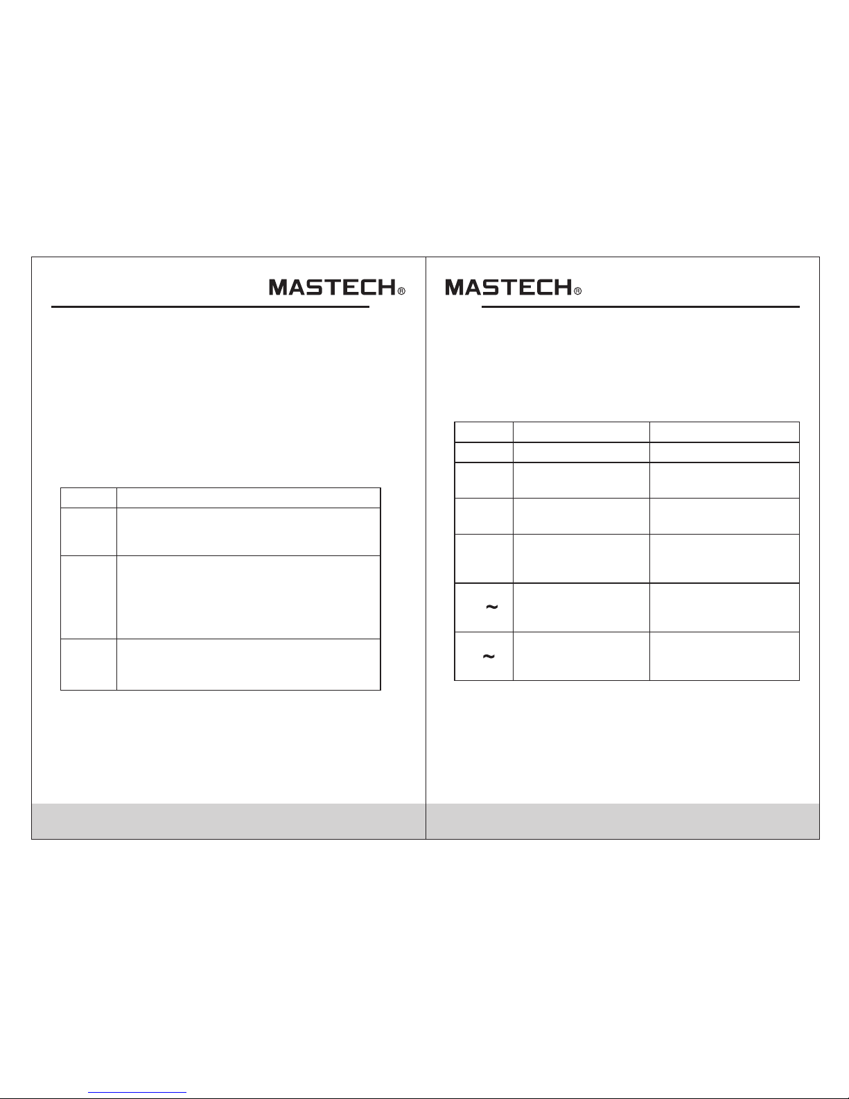
Technical specification
Accuracy: ±(% read + gradu ation #) ambient
temperatur e: 18°C ~ 28°C , Humidity 80%, frequency for
voltage, cur rent: 45 Hz ~ 65 H z
Page 17

29 3 0
Range Accuracy
Resolution
Input
impedance
80V
180V
400V
600V
± (1.0%+5)
0.1V
0.1V
1V
1V
1 MΩ //
10 pF
± (1.0%+5)
± (1.0%+5)
± (1.0%+5)
AC voltage RMS
Max. allowed o verload vo ltage: 750 V (RMS)
Range Accuracy
Resolution
20A
40A
100A
200A
± (2%+5)
0.01A
0.01A
0.1A
0.1A
± (2%+5)
± (2%+5)
± (2%+5)
AC Current RMS
Max. allowed o verload cu rrent: 1200 A
± (2%+5)
± (2%+5)
450A
1000A
1A
1A
Range Accuracy
Resolution
30kW
60kW
120kW
150kW
± (3%+5)
0.01kW
0.01kW
0.1kW
0.1kW
± (3%+5)
± (3%+5)
± (3%+5)
Single-pha se active po wer (W)
Min. test current: 2A; Min . test voltage: 50V
± (3%+5)
± (3%+5)
300kW
600kW
0.1kW
0.1kW
Range Accuracy
Resolution
3kVA
12kVA
30kVA
120kVA
± (3%+5)
0.001kVA
0.01kW
0.01kVA
0.1kVA
± (3%+5)
± (3%+5)
± (3%+5)
Three-phas e active pow er (W)
Min. test current: 2A; Min . test voltage: 50V
± (3%+5)
± (3%+5)
150kVA
600kVA
0.1kVA
0.1kVA
Range Accuracy
Resolution
0.3~1 Capaci tive
0.3~1 Induct ive
± (0.02+2)
0.001
0.001
± (0.02+2)
Power factor
Min. test current: 2A; Min . test voltage: 50V
Range Accuracy
Resolution
3kVAr
12kVAr
30kVAr
120kVAr
± (3%+5)
0.001kVAr
0.01kWr
0.01kVAr
0.1kVAr
± (3%+5)
± (3%+5)
± (3%+5)
Passive powe r
Min. input cur rent: 2A; Mi n. input voltage: 50V
± (3%+5)
± (3%+5)
150kVAr
600kVAr
0.1kVAr
0.1kVAr
Passive powe r Var is c alculate d according to the
measured V, A, an d kW value。
Page 18

29 3 0
Harmonic num ber
Precision of h armonic
voltage
1
2-6
7-8
9-10
± (3.0%+10)
± (3.5%+10)
± (4.5%+10)
± (5.0%+10)
Harmonic test
Min. test voltage 50V;Mi n test current 2A
± (7%+10)
± (10%+10)
11-15
16-20
Range
Accuracy
Resolution
30Hz~1kHz
0.5% + 1
graduation
0.1Hz
Frequency
Min. test voltage: 50 V
Item
Quantity
Instructio n Manual
1.5VAA Battery
Test probe
Test clip
×1
×4
×1
×3
Accessories
Quality Assurance
×1
×1
Interface ca ble
PC Software CD
×1
Package box
Thank you for us ing the prod uct of our company; this
product has a wa rranty per iod of one year starting from
purchasing d ate.
This product h as passed th e strict quality test of our
company. Our compa ny will exer t our efforts to do aftersales servic e for you in acc ordance with the
Warranty instructions.
In case there is a ny problem o ccurred during wa rranty
period, whic h is resulte d from product qual ity proble m,
please fill in t he warrant y card and mail it in tog ether with
the product, a nd the servi ce department of our company
will repair it o r replace it f ree of charge, whil e the user
himself/he rself shal l not take the meter apart.
When warrant y period is ov er, the repairing wi ll be charge d
Free service does not apply to the
following cases:
Problems and d amages due t o improper use or use
under enviro nment whic h is not stipulated f or this
product, inc luding ove rloading.
Problems and d amages due t o unauthorized di smantlin g
or refitting a nd misuse.
Problems and d amages due t o user reasons.
Problems and d amages due t o natural disaste rs.
HYS000000
 Loading...