

Page 1
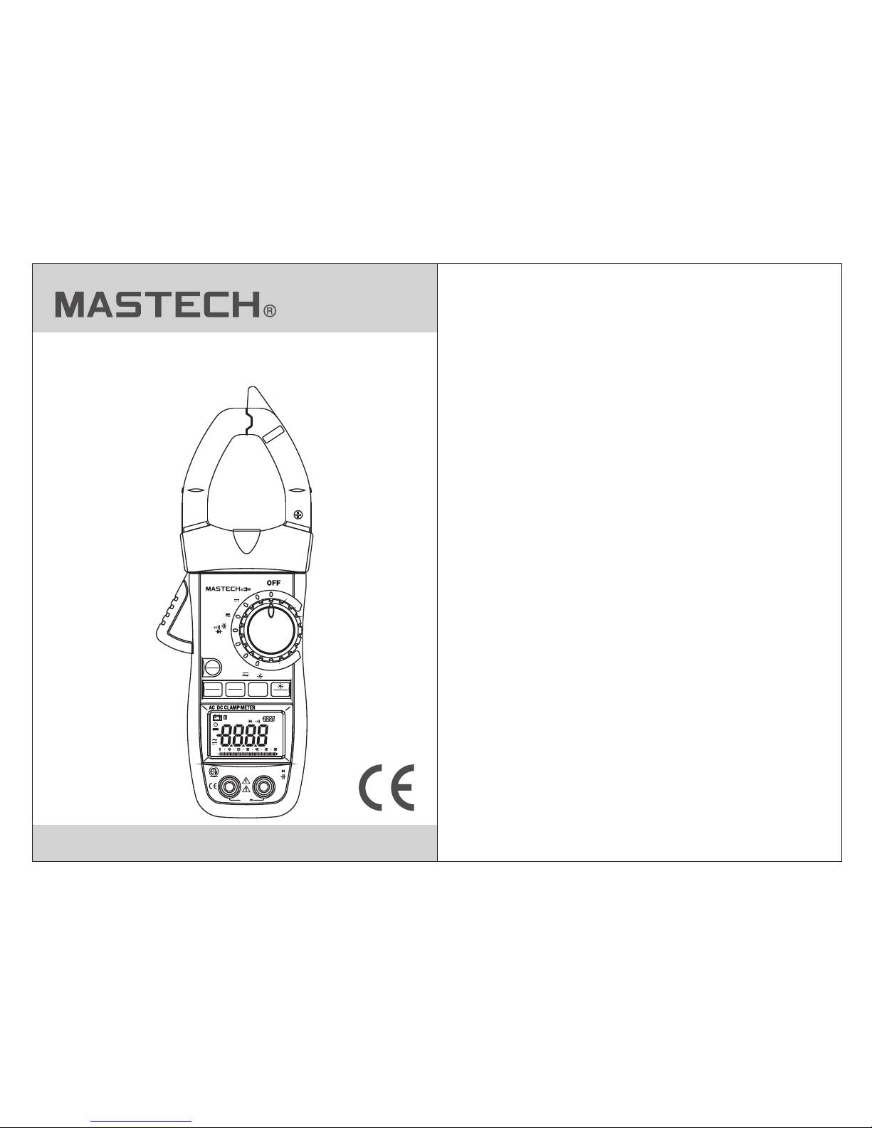
MS2140A
Dual display digital
clamp meter
CAT ll 1000V
A~
Hz
MS2140A
T-RMS
Inrush
TEM P
Hz
μA
Ω
A
V
REL
ZERO
FUNC
INRUSH
HOLD
RANGE
MIN
MAX
COM
Temp μAHz
ΩV
RELINP MAX MIN
°C%
kHz
°F
µmVA
nµmF
MkΩHz
AUTO
K-T
NCV
MAX
1000V
Press 2Sec
CAT lll 600V
600A
TRMS
AutoRange
C
US
intertek
3080912
Page 2

CONTENTS CONTENTS
1. Safety Information.............................1
1.1 Preparation..............................................1
1.2 Usage.......................................................2
1.3 .....................3 Safety symbols on the meter
1.4 Maintenance............................................4
2. ................4Features and Components
2.1 ............................................5 Components
2.2 ................................7Buttons and switches
2.3 ..................................7Display Description
3. Specification.....................................9
3.1 ..............................9General Specifications
3.2 ..........................10Technical Specifications
4. .............................16Operations Guide
4.1 ...........................................16Display Hold
4.2 ..............................16Manual Measurement
4.3 ........................16Backlight and Clamp light
4.4 ................17 Maximum/Minimum recording
4.5 ..................................17Function switching
4.6 ...............................................17ZERO/REL
5. Maintenance......................................24
5.1 ..........................24Replacing the batteries
5.2 ...........................25Test Leads Replacement
6. .......................................25Accessories
4.7 ...................................................18INRUSH
4.8 ..........................................18Auto Power Off
4.9 .............................18Measuring Preperation
4.10 .............................19Current Measurement
4.11 .............................19Voltage Measurement
4.12 ......................20Frequency and Duty Cycle
4.13 .............................................20Resistance
4.14 ..............................................21Diode Test
4.15 ...............................................21Continuity
4.16 ...........................................22Capacitance
4.17 ..................22Inrush Current Measurement
4.18 ...........................................23Temperature
4.19 ........................23μA Current Measurement
4.20 ...................23NCV Sensitivity and settings
Page 3
01 02
1. Safety Information
This m eter ha s met IEC 61010 -1 and IEC-61010-2-03 2
stan dards w ith an ov ervol tage category of 600V CAT III
and a polluti on degr ee of 2. Fo llow safe operation
procedure s to ensu re the lo ng life and safe use of this
instrumen t.
WARNING
1.1 Preparation
1.1. 1 When us ing the m eter, fo llow the following
safe ty rule s:
-Take pr ecaut ions to p reven t electrical shock
-Do no t misus e the ins trume nt
1.1. 2 Check t he mete r and acc essories thoroughly
befo re usin g.
1.1. 3 Check t o see if th e meter o r any components
were d amage d durin g shipm ent.
1.1. 4 Inspe ct test l eads an d probes for cracks, brea ks
or cra zes on th e insul ation b efore using the meter.
1.1. 5 Use tes t leads p rovid ed with the unit. If
nece ssary, rep lace te st leads with identical
spec ifica tions .
1.2 Usage
1.2. 1 Turn the r otary s witch t o the required function
and ra nge to be m easur ed.
1.2. 2 Never u se the me ter to me asure voltages that
migh t excee d 600V DC /AC abo ve earth ground.
1.2. 3 Always b e caref ul when w orking with voltages
abov e 60V DC or 3 0V AC RMS. K eep fin gers
behi nd the pr obe bar riers w hile measuring.
1.2. 4 Th e “ ” symbo l next to t he input lead shows
that t he inpu t volta ge or current should not
exce ed the sp ecifi ed valu e in order to protect the
inte rnal ci rcuit f rom dam age.
1.2. 5 Choos e the hig hest ra nge when the value to be
meas ured is u nknow n.
1.2. 6 Remov e test le ads bef ore switching functio ns on
the ro tary sw itch.
1.2. 7 Do not pe rform r esist ance, capacitance, di ode
and co ntinu ity mea surem ents on powered circuit s.
1.2. 8 Never c onnec t the tes t leads across a voltage
sour ce whil e the rot ary swi tch is in the resistance,
diod e or cont inuit y mode. D oing so can damage
the me ter.
1.2. 9 Power o ff t he circ uit and d ischarge capacitors
befo re test ing cap acita nce.
1.2. 10 Do not p lace th e meter i n any environment with
high p ressu re, hig h tempe rature, dust, ex plosi ve
gas or v apor.
1.2. 11 St op usin g the met er if any f ailure or abnormal
func tion is o bserv ed.
1.2. 12 Do not u se mete r unles s battery cover is in place
a secu red.
TO REDUC E THE RIS K OF FIRE , ELECTRICAL
SHOC K, PROD UCT DAM AGE OR PE RSONAL
INJU RY, PLEA SE FOLL OW THE SA FETY
INST RUCTI ONS DES CRIBE D IN THE USER
MANUAL. REA D THE USE R MANUA LS
BEFO RE USIN G THE MET ER.
Page 4
03 04
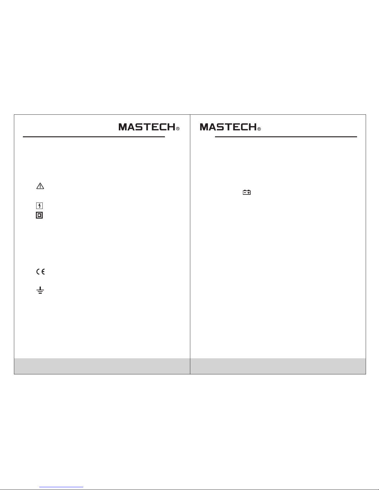
1.3 Safety symbols on the meter
Impo rtant s afety i nform ation; please refer to
user manual
High voltag e
Complianc e with re quire ments for double
insu latio n
Refe rs to the i mpuls e withs tand voltage
protectio n level i n accor dance with IEC-61010- 1
stan dard ov ervol tage (i nstallation) catego ry III,
pollution d egree 2 .
Mete r compl ies wit h Europ ean Community
(CE) standa rds
Earth groun d
1.4. 1 To avo id elec tric sh ock or pe rsonal injury, repairs
or ser vicin g not cov ered in t his manual should be
perf ormed o nly by qu alifi ed personnel.
1.4. 2 Remov e test le ads bef ore opening battery cov er
1.4. 3 To avo id inco rrect r eadin gs causing electric
shoc k or pers onal in jury, when low battery
symb ol “ ”app ears re place batteries immed iatel y.
1.4. 4 Th e meter c an be cle aned wi th a soft cloth to
remo ve any oi l, grea se or gri me. Do not use
liqu id solv ent or de terge nt.
1.4. 5 When th e instr ument i s not in use, turn rotary
swit ch to “OF F”
1.4. 6 If the in strum ent is no t to be used for an extended
peri od of tim e, remo ve the ba tteries to preve nt
dama ge to the i nstru ment.
1.4 Maintenance
2. Features and Components
The CM 660 is a po rtabl e, hand -held yet professiona l
mete r that fe ature s an LCD wi th backlight, overloa d
protectio n and low b atter y indicator. These meters ar e
easy to use wit h one han d, suit able for professional
users or amat eurs, a nd idea l for school or home use.
CAT III
1.2. 13 Avoid dir ect sun light , exposing batteries to
humi dity, any st rong ma gnetic field, or high
temp eratu res to en sure the extended life of
the me ter.
-Aut o and man ual ran ge
-Reading Ho ld func tion
-Max m easur ement
-Min m easur ement
-Fre quenc y in clam p mode
-Aut o power o ff
-Relative m easur ement
- Inru sh meas ureme nt
Page 5
05 06
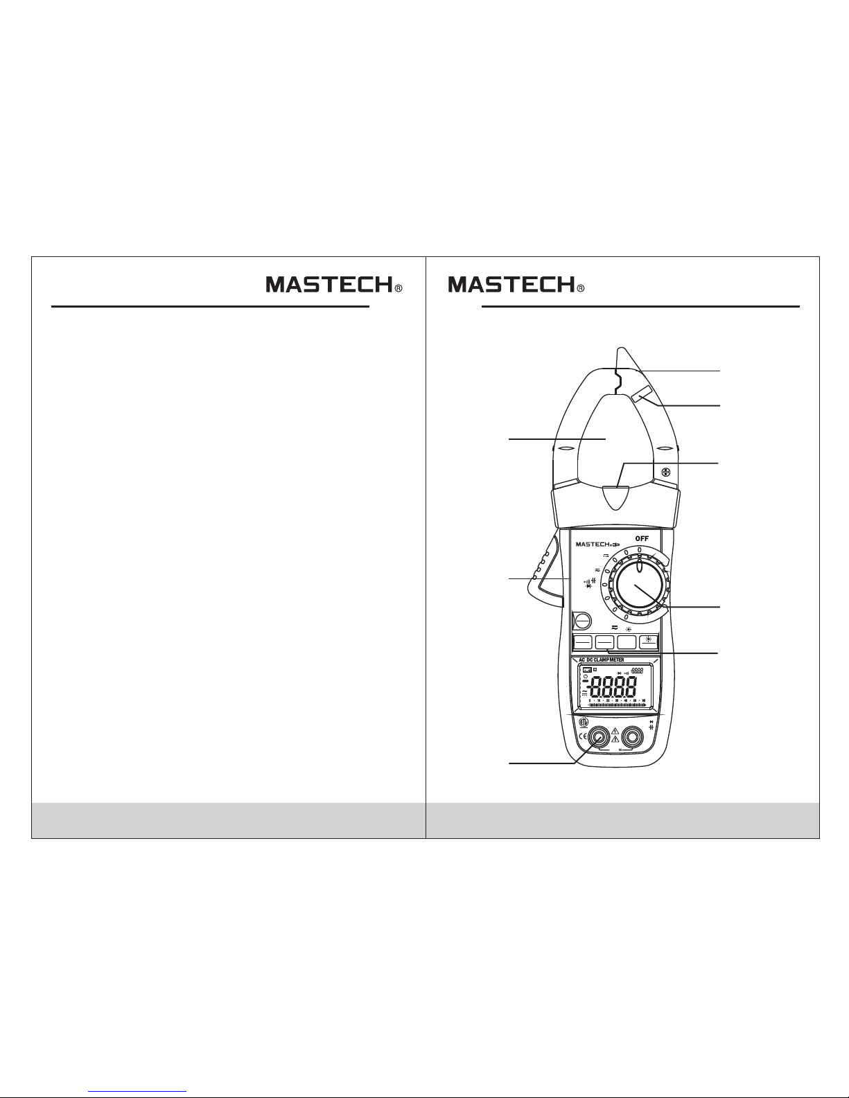
(1) No n-Con tact Vol tage de tection sensor
(2)N CV indi cator
(3)Wor k light
(4)R otary S witch
(5)F uncti on butt ons
(6)I nput so ckets
(7)C lamp tr igger
(8)C lamp: f or curr ent mea surement
2.1 Components
1
2
3
4
5
6
7
8
CAT ll 1000V
A~
Hz
MS2140A
T-RMS
Inrush
TEM P
Hz
μA
Ω
A
V
REL
ZERO
FUNC
INRUSH
HOLD
RANGE
MIN
MAX
COM
Temp μAHz
ΩV
RELINP MAX MIN
°C%
kHz
°F
µmVA
nµmF
MkΩHz
AUTO
K-T
NCV
MAX
1000V
Press 2Sec
CAT lll 600V
600A
TRMS
AutoRange
C
US
intertek
3080912
Page 6
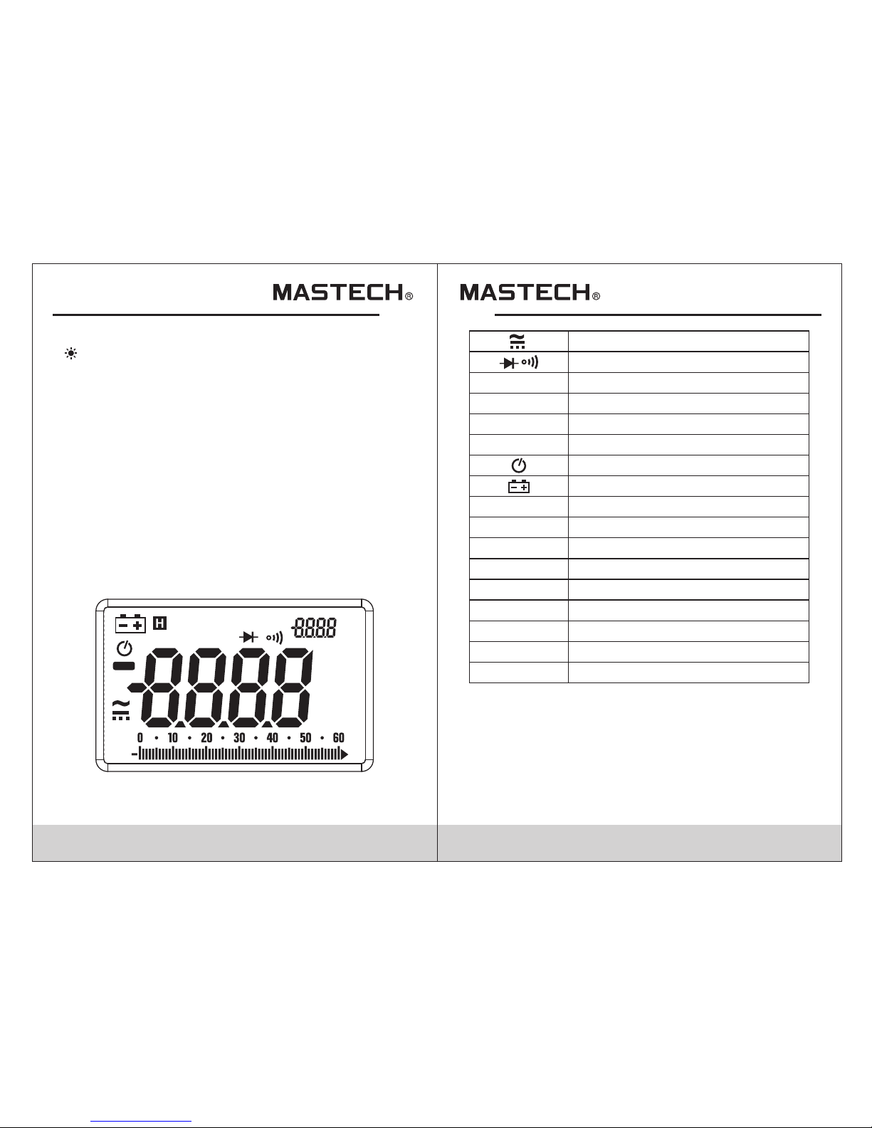
AC/D C
Diode, Cont inuit y
Auto -rang e
Maxi mum/M inimu m displ ay
Inru sh
Relative me asure ment mo de
Auto P ower Off
Display Hold
Perc entag e (Duty C ycle)
millivolt s, volt s, amps
nanofarad , micro farad , millifarad
Non-conta ct volt age
ohms, kilio hms, me gaohm s
hertz, kilo hertz , megah ertz
K-ty pe ther mocou ple mea surement
K-T
Hz, kHz, MHZ
nF,μF,mF
mV,V,A
%
AUTO
MAX /MIN
INR
REL
H
celcius, fa hrenh eit
°C,°F
Low Battery
NCV
Ω,kΩ,MΩ
07 08
2.3 Display Description
2.2 Buttons and switches
/RAN GE butt on: bac kligh t/switch ranges in
manual mode
FUNC button : switc h measu rement functions
HOLD b utton : hold re ading o n screen
REL/ ZERO bu tton: r elati ve reading/DC zero offset
INRU SH butt on: mea sure In rush current
MAX/ MIN but ton: sw itch be tween max/min reading s
Rota ry Swit ch: swi tch bet ween measurements
INPU T jack: v oltag e, curr ent, resistance, capa citan ce,
diod e, cont inuit y, fr equency, duty cycle ,
temp eratu re inpu t terminal
COM ja ck: com mon inp ut term inal
RELINP MAX MIN
°C%
kHz
°F
µmVA
nµmF
MkΩHz
AUTO
K-T
NCV
Page 7
09 1 0
3. Specifications
• Manual and Aut o Mode
Power Overl oad Pro tecti on
Maxi mum Volt age Bet ween Ci rcuit and Ground:
1000 V DC or 100 0V AC
Maxi mum Worki ng Heig ht: 200 0m
Display: LC D
Maxi mum Dis play Nu mber: 5 999
Auto P olari ty Indi catio n, '-'Indicates Negat ive
Over load In dicat ion: '0 L' Or '-0L'
Samp ling Fr equen cy: 4 Time s / Sec
Units Displ ay: Dis play Fu nctions and Units.
Auto P ower Off: 2 0 Minut es
Inpu t Power : 4 .5V DC
Batt ery Type: AAA
Low Battery I ndica tion: L CD Display “ ”
Temperature : Less Than 0 .1 X Spec ified Accuracy/°C
Workin g Envir onmen t Temp eratu re: 18°C ~28°C
Stor age Tempera ture: -10°C ~ 50°C
Size 238×92 ×50mm
Weight : ~420g ( Inclu ding ba ttery)
•
•
•
•
•
•
•
•
•
•
•
•
•
•
•
•
•
•
The Me ter sho uld be ca libra ted annually between
18°C ~ 2 8°C and a r elati ve humi dity less than 75%.
3.1 General Specifications
3.2 Tec hni cal S pec ifi cat ion s
3.2. 1 True RMS C harac teris tics
3.2. 1.1 For n on-si nusoi dal signal measuremen ts,
true R MS is a mor e accur ate method of
meas ureme nt over t he averaging method.
3.2. 2 AC Cur rent
Accuracy
Resolution
Range
±(1.8% of reading + 10 digits)
60A
600A
0.01 A
0.1A
- Maxi mum inp ut curr ent: 60 0A AC
- Freq uency r ange: 5 0 ~ 60Hz
3.2. 3 DC Curr ent
Accuracy
Resolution
Range
±(3% of reading + 10 digits)
60A
600A
0.01 A
0.1A
-Maximum in put cur rent :6 00A DC
3.2. 4 Inrus h Curre nt
Inte grati on time : 100ms ; Measuring range: 10 ~ 600 A;
Accuracy
Resolution
Range
60A
600A
0.01 A
0.1A
< 60A for r efere nce onl y
±(10 % readi ng + 60 dig its)
Page 8
11 12
3.2.5 DC Voltage
Accuracy
Resolution
Range
±(0.5% of reading + 3 digits)
0.1V
0.01 V
0.00 1V
0.1m V600mV
6V
60V
600V
-Inp ut impe dance : 10MΩ.
-Max imum in put vol tage: 600V AC (RMS) or 600V DC
-600 mV rang e: only b y press ing RANGE button.
3.2. 6 AC Voltag e
Accuracy
Resolution
Range
±(0.8% of reading + 3 digits)
0.1V
0.01 V
0.00 1V
0.1m V600mV
6V
60V
600V
Note :
At sma ll volt age ran ges, un steady readings will ap pear
befo re the te st lead s make co ntact with the circuit.
This is no rmal si nce the M eter is h ighly sensitive.
When t he test l eads ar e conne cted to the circuit, the
true r eadin g will be s hown.
Note :
At smal l volta ge rang es, uns teady readings will app ear
befo re the te st lead s make co ntact with the circuit.
This is no rmal si nce the M eter is h ighly sensitive.
When t he test l eads ar e conne cted to the circuit, the
true r eadin g will be s hown.
-Inp ut impe dance :10MΩ .
-Max imum in put vol tage: 6 00V AC (RMS) or 600V DC
-Fre quenc y range :50 ~ 60H z
-600mV rang e: only b y press ing RANGE button.
3.2. 7 Frequ ency
Accuracy
Resolution
Range
0.01 Hz
60Hz
-Mea surin g range : 10Hz ~ 1k Hz
-Inp ut rang e≥1A AC (RMS) ( Input c urren t should
incr ease as c ircui t frequ ency increases.)
3.2. 7.1 Fre quenc y throu gh Clamp Measuri ng (A Mo de)
±(1.5% of reading + 5 digits)
600Hz 0.1H z
3.2. 7.2 Fre quenc y throu gh “V” mode:
Accuracy
Resolution
Range
0.01 Hz60Hz
±(1.5% of reading + 5 digits)
0.1H z
1Hz
-Mea surin g range :10Hz ~ 1 kHz
-Inp ut rang e≥20mA AC(R MS) (In put cur rent should
incr ease as c ircui t frequ ency increases.))
6kHz
1Hz
10Hz60kHz
600Hz
6kHz
1V
1000V
1V
1000V
Page 9
13 14
3.2.7.3 Fre quenc y Throu gh “HZ” Mode:
- Input signal: VPP 3V square wave; Overload
Protection: 250V DC or AC (RMS)
3.2.8 Duty Cy cle
Accuracy
Resolution
Range
5-95% ±3.0% 0.1%
Accuracy
Resolution
Range
0.01 Hz
60Hz
±(0.3% of reading + 5 digits)
0.1H z
1Hz
0.01 kHz
60kHz
600Hz
6kHz
0.1k HZ
1kHZ
0.01MHZ60MHZ
600kHZ
6MHZ
Accuracy
Resolution
Range
±(0.8% of reading + 3 digits)
3.2. 9 Resis tance
±(1.2% of reading + 3 digits)
60MΩ
600Ω
6kΩ
60kΩ
600kΩ
6MΩ
0.00 1kΩ
0.1Ω
0.01 kΩ
0.1k Ω
0.00 1MΩ
0.1M Ω
- Over load pr otect ion: 25 0V DC or AC (RMS)
When measuring frequencies > 60KHz, duty cycle
measurement range is 10 to 90%
3.2. 11 Capac itanc e
- Over load pr otect ion: 25 0V DC or AC (RMS)
3.2. 12 Diod e
Accuracy
Resolution
Range
- Forw ard DC cu rrent : about 1 mA
- Open c ircui t volta ge: abo ut 2.8V
- Over load pr otect ion: 25 0V DC or AC (RMS)
0.00 1V
Displays ap proxi mate
forw ard vol tage.
Accuracy
Resolution
Range
3.2. 10 Cont inuit y
- Over load pr otect ion: 25 0V DC or AC (RMS)
- Open c ircui t volta ge: abo ut 3V
0.1Ω
The Me ter wil l beep if
measureme nt is les s
than 5 0
Accuracy
Resolution
Range
±(4.0% of reading + 5 digits)
6nF
60nF
600nF
6µF
60µF
600µF
6mF
60mF
0.00 1nF
0.01 nF
0.1n F
0.00 1µF
0.01 µF
0.1µ F
0.00 1mF
0.01 mF
±(5.0% of reading + 5 digits)
Page 10
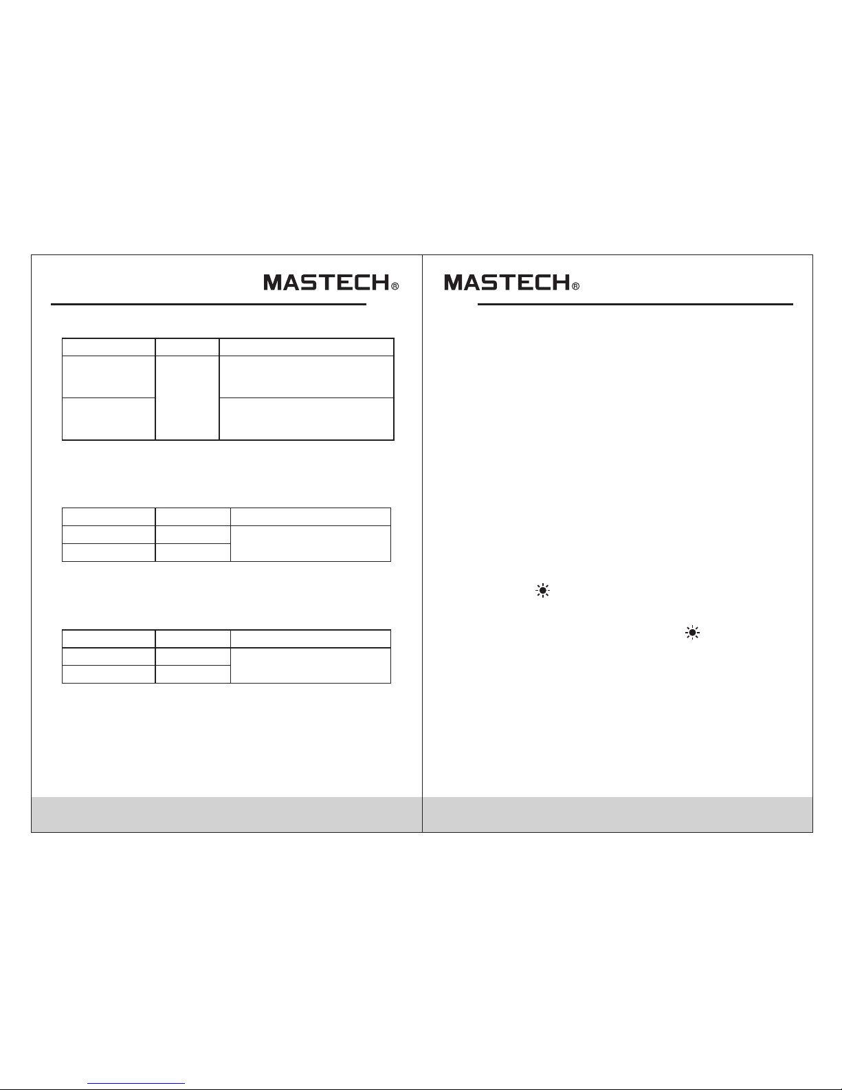
3.2. 13 Tempera ture
Note: Th e accur acy doe s not inc lude K-type
ther mocou ple err or.
16
15
During meas uring , press t he “HOLD” button once to
hold the read ing, pr ess aga in to release hold.
4. Operations Guide
4.1 Display Hold
4.2 Manual Measurement
When u sing th e rotar y switc h to switch between curre nt,
voltage, ca pacit ance an d frequency mode, the def ault
range type is Au to. Pre ss “RAN GE” button to enter
manual mode . Each pr ess inc reases the measuring
range and wil l retur n to auto -range after maximum ha s
been reache d.
Manual Meas ureme nt Mode i s disabled when
performin g frequ ency me asurement.
Note:
4.3 Backlight and Clamp light
1) Pre ss the “ /R ANGE” butto n for 2 seconds to tur n
on the d ispla y backl ight; t he backlight will stay on
for 20 s econd s befor e it is aut omatically turned off.
2)Wh en the ba cklig ht is on, p ress the “ /RANGE”for
2 seco nds to tu rn off the ba cklig ht.
3) In cu rrent m ode, tu rning o n the backlight will also
trig ger the c lamp li ght
Note : Backl ight/ clamp l ight uses and LED; even
thou gh the li ght wil l auto off after 20 seconds,
use on ly when n eeded t o conse rve power.
Accuracy
Resolution
Range
0.1° C/
0.2° F
±1.0 % of read ing + 0.8 °C
(±1. 0% of reading + 0.8°F)
-10°C~500°C
(-14°F to 932°F)
-40°C~ -10°C
(-40°F to -14°F)
±5.0 % of read ing + 1.5 °C
(±5. 0% of reading + 3.3°F)
3.2.14 AC µA Current
Accuracy
Resolution
Range
200.0µA
0.1µ A
2000µA
±(1.0% of reading + 5 digits)
1µA
-Fre quenc y range : 50 ~ 60Hz ;
- Over load pr otect ion: 25 0V DC or AC (RMS)
3.2.15 DC µA Current
Accuracy
Resolution
Range
200.0µA
0.1µ A
2000µA
±(1.0% of range + 5 digits)
1µA
- Over load pr otect ion: 25 0V DC or AC (RMS)
Page 11

17 18
4.4 Maximum/Minimum recording
1) Pre ss “MAX /MIN” b utton o nce to display the
maxi mum mea surem ent and p ress “MAX/MIN”
butt on agai n to disp lay the m inimum, press
“MAX /MIN” b utton a t hird ti me to return to
norm al mode .
2) In Ma x/Min m ode, me asure ment is saved
auto matic ally.
3) Max /Min va lues ar e displ ayed on the secondary
disp lay whi le the cu rrent m easured value is
disp layed o n the mai n displ ay.
Note:
1) The Met er is set t o manua l mode wh en using
Max/ Min mea surem ent.
1) Whe n rotar y switc h is on Res istance, Diode,
capa citan ce, and c ontin uity mode, press “FUNC”
butt on to swi tch bet ween th ose four.
2) Whe n rotar y switc h is on Volt age and Current mode,
pres s “FUNC ” butto n to swit ch between AC and DC.
4.5 Function switching
1) Pre ss “ZER O/REL ” butto n to enter relative
meas ureme nt mode . When in t his mode, the current
read ing wil l be stor ed and sh own on the secondary
disp lay whi le the ma in disp lay with show the
differ ence of c urren t readi ng and stored reading.
REL (Outpu t) = (cur rent re ading) – (reading when
butt on pres sed).
2) “RE L” can on ly perf orm und er manual mode.
4.6 ZERO/REL
4.7 INRUSH
When i n AC Curre nt meas ureme nt mode, press the
“INR USH” bu tton to e nter su rge current measureme nt
mode. Press b utton a gain to r eturn to normal mode.
4.8 Auto Power Off
1) Whe n not in us e, the me ter wil l automatically turn
off afte r 20 minu tes.
2) Afte r Auto Off, pr ess any b utton t o bring power
back o n.
3) To disabl e Auto Off, ho ld “ZER O/REL ” when turning
on the M eter.
4) Whe n auto po wer off is on , symbo l appears on,
symb ol appe ars on sc reen. s creen.When disabled ,
symb ol does n ot appe ar.
4.9 Measuring Preperation
1) Turn on the met er by tur ning th e rotary switch.
If bat tery vo ltage i s low ( 3.6V), “ ” appears;
repl ace the b atter y.
2) “ ”in dicat es inpu t volta ge or current should not
exce ed the in dicat ed valu e; this is to protect the
mete r from da mage.
3) Turn the rota ry swit ch to the p roper position.
4) Whe n conne cting t o the cir cuit, connect COM input
firs t befor e conne cting t o power. Remove the power
lead f irst wh en disc onnec ting from the circuit.
Page 12

19
20
4.10 Current Measurement
1) For AC curren t move ro tary sw itch to A~ position;
for DC c urren t move ro tary sw itch to A position.
2) Ope n the cla mp head b y press ing the trigger and
inse rting t he cond uctor t o be measured.
3) Whe n measu ring AC cu rrent , the main display
show s the mea sured c urren t value while the
seco ndary d ispla y shows t he frequency of the
meas ured cu rrent
Note:
1) Mea surin g two or mo re wire s together will cause
fals e readi ngs.
2) The wir e being m easur ed shou ld be centered within
the cl amp.
3) “ ”in dicat es the ma ximum i nput AC/DC current is
600 A.
4) For h igher a ccura cy, when mea suring DC current
if Dis play sh ows non z ero, pr ess “ZERO/REL”
butt on to res et the re ading t o zero.
Note :
1) Whe n measu ring lo w volta ge source, the meter
When m easur ing low v oltag e sources, the reading
will f luctu ate on th e displ ay when the test leads are
not co nnect ed to the c ircui t. This is normal due to
the hi gh sens itivi ty of the M eter. The Meter will
disp lay cor rect re ading o nce the leads are
conn ected t o the cir cuit.
4.12 Frequency and Duty Cycle
1) Ins ert the b lack te st lead s into “COM” input and red
test l ead int o “INPU T” inpu t
2) Turn rotary s witch t o “Hz” po sition.
3) Connect te st lead s to the vo ltage source or
betw een loa ds.
Note:
Freq uency r ange is 1 0Hz ~ 60M Hz. For frequencies
below 10Hz, d ispla y will sh ow “00. 0.” For frequenc ies
about 60kHz , duty cy cle mea surement accuracy is
not gu arant eed.
4.11 Vol tag e Mea surement
1) Ins ert the b lack te st lead s into “COM” input and red
test l ead int o “INPU T” inpu t, choose proper range.
2) Move rotar y switc h to V posi tion. AC voltage is
defa ult mea surem ent. Pr ess “FUNC” to switch to
DC vol tage.
3) For m V measu remen t, pres s “RANGE” button until
in mV ra nge.
4) Connect te st lead s to volt age source or load.
5) Voltage mea surem ent wil l be show n on main display.
4.13 Resistance
1) Ins ert the b lack te st lead s into “COM” input and red
test l ead int o “INPU T” inpu t
2) Turn rotary s witch t o “ ” posit ion for resistance
meas ureme nt.
3) Connect th e test le ads acr oss the circuit or resist ors
and re ad valu e on LCD.
Page 13

21
22
Note:
1) When the circuit is an open circuit, the Meter displays
“OL” for overload.
2) For measurements above 1MΩ, the meter will take a
few seconds to stabilize the reading; this is normal
for high resistance measurements.
4.14 Diode Test
1) Insert the black test leads into “COM” input and red
test lead into “INPUT” input
2) Turn rotary switch to “ ”position and push “FUNC”
twice for diode test.
3) Connect the black lead to the cathode (-) and the
red lead to the anode (+) and read the value from
the LCD.
1) The meter displays the forward biased value.
2) If the diode is connected backward or is an open
circuit, the Meter will display “OL”.
Note:
Note:
The Meter displays “OL” if the circuit is open or
resistance is larger than 600Ω.
4.16 Capacitance
1) Insert the black lead into “COM” input and the red
lead into “INPUT” input.
2) Turn the rotary switch to “ ” position and push
“FUNC” three times for capacitance .
3) Place leads at the terminals of the capacitor after it is
fully discharged.
4) Read the measurement from the display.
4.17 Inrush Current Measurement
1) Turn rotary switch to “A” position
2) Push “INRUSH”button to enter inrush current mode.
3) Open the clamp head by pressing the trigger and
inserting the conductor to be measured.
4) Power on the circuit being tested
5) Largest value will be held on main display
4.15 Continuity
1) Insert the black test leads into “COM” input and red
test lead into “INPUT” input
2) Turn rotary switch to “ ” position and push “FUNC”
once for continuity test.
3) Connect leads to the circuit terminals.
4) The meter will beep if the reading is below 50Ω.
5) Screen will show resistance value
Note::
1) Measuring two or more wires together will cause false
readings.
2) The wire being measured should be centered within
the clamp.
3) The Meter displays “OL” if the circuit is overloaded.
Choose a larger range if possible.
4) Choose the largest range if the range of the circuit is
unknown.
Page 14
23 2 4
1) Turn rotary switch to “TEMP” position.
2) Insert K-type thermocouple into the multi-function
socket with the “+” end in “INPUT” input and “-“ into
“COM” input.
3) Temperature reading will show on main display.
4.18 Tempe rature
4.19 μA Current Measurement
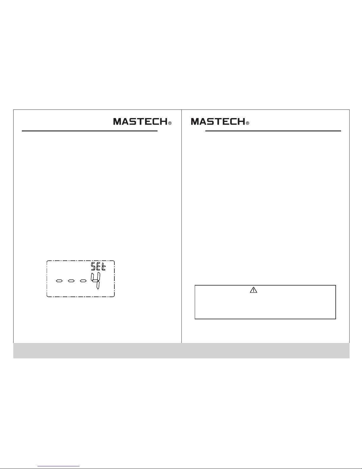
4.20 NCV Sensitivity and settings
1) Hold “FUNC ” when yo u turn on t he meter and the
foll owing d ispla y will sh ow up on the LCD:
2) Pus h the “RA NGE” bu tton to a djust the NCV
sens itivi ty from 0 -4. '4' i s the highest sensitivi ty
wher e '0' wil l turn off th e NCV fun ctionality.
3) Pus h the “HO LD” but ton to sa ve the selected
sens itivi ty and re turn to n ormal meter operation .
4) Wit h the NCV f uncti on acti ve (sensitivity betwe en
1-4) , if the se nsor at t he top of the clamp gets clos e
to a liv e condu ctor (A C volta ge >90V) the NVC
indi cator w ill fla sh and bu zzer will sound.
Note:
1) Eve n thoug h there i s no indi cation, voltage may sti ll
exis t. Do not r ely sol ely on NC V detector to determine
the pr esenc e of volt age in a wi re. The measurement
may be a ff ected b y the des ign of th e outlet, type of
insu latio n and oth er exte rnal factors.
2) The vol tage se nsing i ndica tor may turn on when a
volt age is fe d to the me ter.
3) Oth er exte rnal in terfe rence (ex. Flashlight , motor )
may tr igger t he NCV se nsor.
1) Insert the black lead into “COM” input and the red
lead into “INPUT” input.
2) Turn the rotary switch to μA position.
3) Push “FUNC” to switch between AC/DC current
4) Connect test leads to circuit.
5) Current measurement will be shown on main display.
NCV
5. Maintenance
5.1 Replacing the batteries
TO AVOID ELE CTRIC AL SHOCK, P RODUCT
DAMAGE OR PER SONAL INJ URY, REM OVE
TEST L EADS BE FORE OP ENNIN G BATTERY
COVE R.
WARNING
Page 15
25
1) If “ ”s ymbol a ppear s, this i ndicated batte ries
shou ld be rep laced .
2) Unscrew th e instr ument 's battery cover and remo ve it
3) Replace ba tteri es
4) Replace th e batte ry cove r and tighten screws
Note:
Be sur e to note t he batt ery pol arity when replacing.
5.2 Tes t Lea ds Re pla cement
REPL ACE THE T EST LEA DS WITH IDENTICAL
OR COM PATIBL E LEADS . LEAD SP EC:
1000V 10A.
WARNING
Replace new l eads if t he curr ent leads are worn.
6. Accessories
1) Test Lead s: Rati ng:10 00V 10A 1 pair
2) Use r ’s M anual 1 pc
3) Bat terie s: AAA Batt ery 3 pc
4) K-t ype the rmoco uple 1 pc
5) Mul ti-fu nctio n socke t 1 pc
00-05-3465
 Loading...