

Page 1
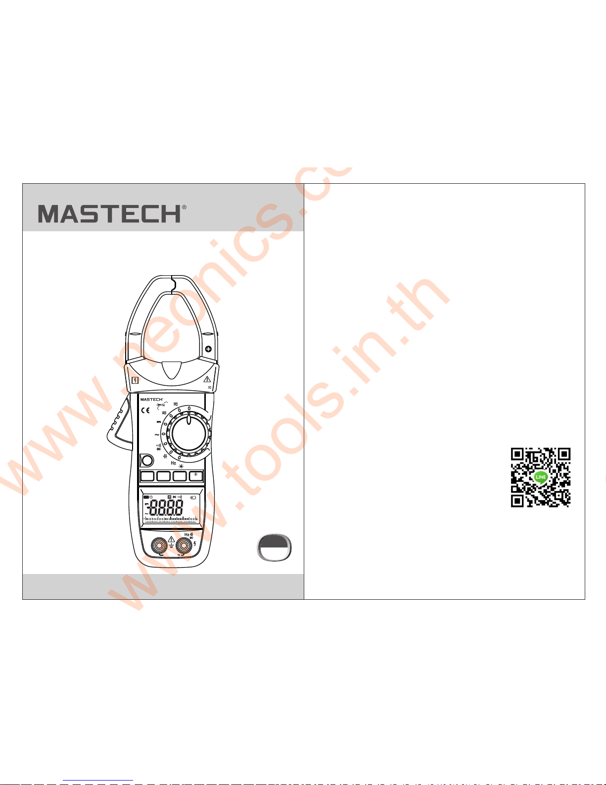
MS2138/R
AC/DC DIGITAL CLAMP METER
OPERATION MANUAL
AUTO
%
40302010
0
REL
DC
AC
MK
Hz
Ω
mnVAF
μ
FUNC.
RANGE
HOLD
Hz/%
REL
AUTO-POWER OFF
600V CAT III
MAX100
A
600V
CAT III
MAX 600 V
COM
VΩ
Press 2 Sec
Ω
V
OFF
100
40/400
MS21 38
A
V
A
AC/DC CLAMP METER
Auto Range
CAT III
600 V
www.
tools.in.th
ติดต่อบริษัท นี โอนิคส์ จํากัด
Tel: 02-077-7602 หรือ 061-8268939
E-mail: sale@tools.in.th หรือ sale@neonics.co.th
www.neonics.co.th
Page 2
CONTENTS CONTENTS
1. Safety Information.............................1
1.1 Preliminary...............................................1
1.2 During Use...............................................2
1.3 Symbols...................................................3
1.4 Maintenance............................................4
2. Description........................................4
2.1 Names Of Parts........................................5
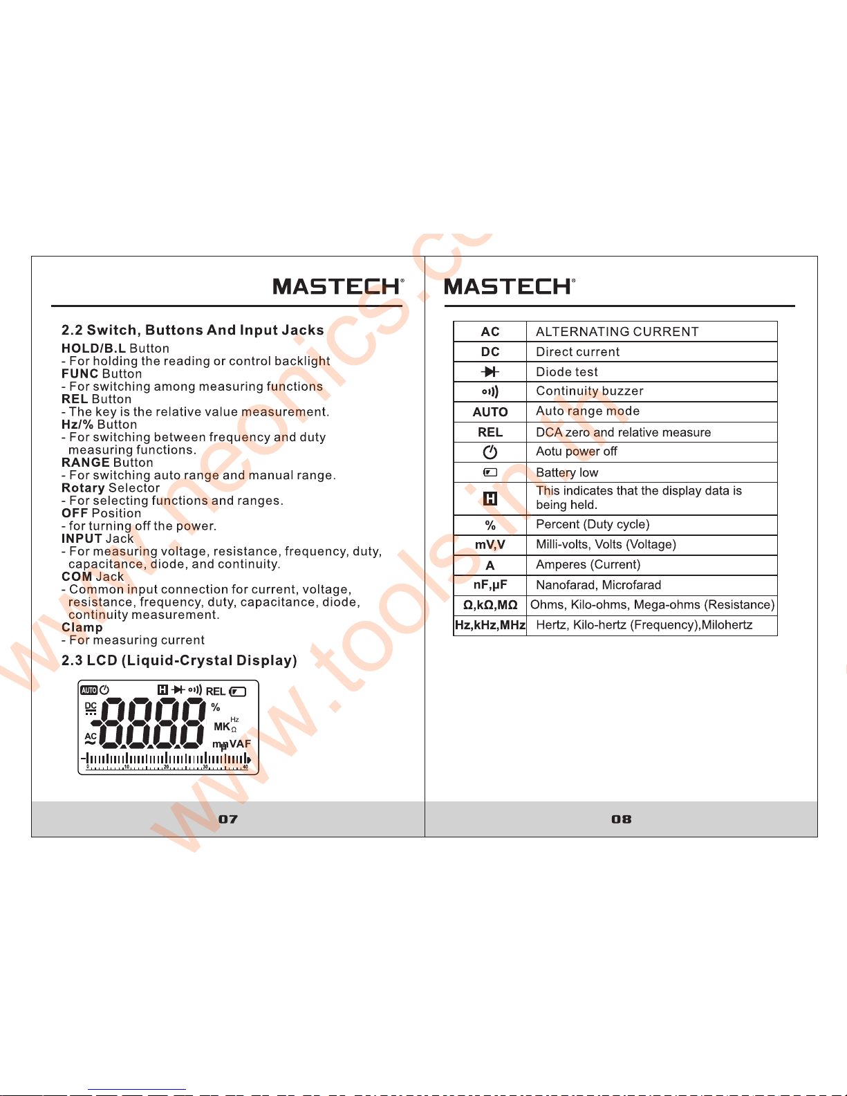
2.2 Switch, Buttons And Input Jacks...............7
2.3 LCD (Liquid-Crystal Display)....................7
3. Specifications...................................9
3.1 General Specifications.............................9
3.2 Technical Specifications.........................10
4. Operation Instruction......................15
4.1 Holding Readings...................................15
4.2 Switching REL........................................15
4.3 Switching Frequency Or Duty..................16
4.4 Switching Manualrange
Or Auto Range ..................................16
4.5 Switching Functions.................................17
4.6 Back Light And Clamp Lighting Bulb..........17
4.7 Auto Power Off.........................................18
4.8 Preparing For Measurement.....................18
4.9 Measuring AC Current .............................19
4.10 Measuring DC Current ...........................20
4.11 Measuring AC Voltage ............................21
4.12 Measuring DC Voltage ...........................21
4.13 Measuring Frequency ............................22
4.14 Measuring Duty .....................................24
4.15 Measuring Resistance............................27
4.16 Testing Diode.........................................28
4.17 Testing Continuity...................................29
4.18 Measuring Capacitance .........................29
5. Maintenance......................................30
5.1 Replacing The Batteries............................30
5.2 Replacing Test Leads ...............................31
6. Accessories.......................................31
www.neonics.co.th
Page 3
www.neonics.co.th
Page 4
03 04
1.2.11 Do not use the meter near explosive gases,
steam or dirt.
1.2.12 Stop using the meter if any abnormalities or
faults are observed.
1.2.13 Do not use the meter unless its rear case and
battery cover is securely fastened in its original
position.
1.2.14 Do not store or use the meter in areas exposed
to direct sunlight, at high temperature or with high
relative humidity.
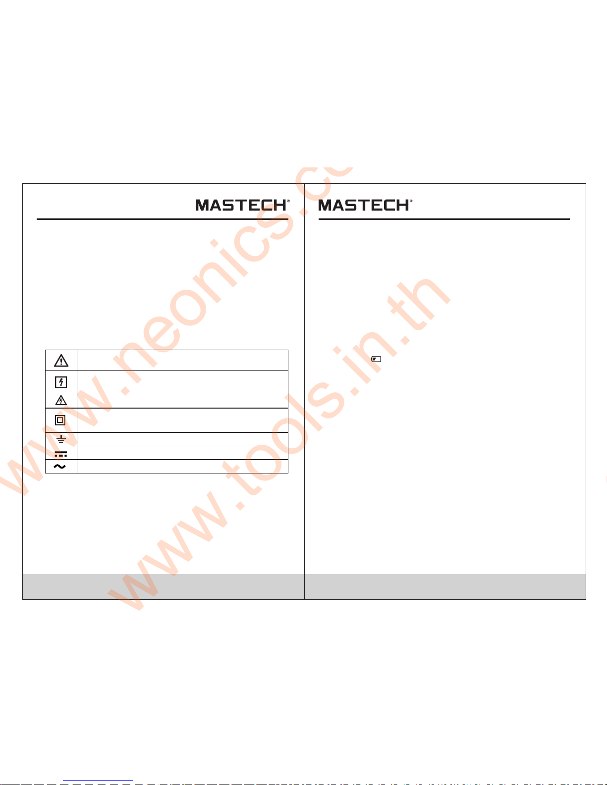
1.3 Symbols
1.4 Maintenance
1.4.1 Do not attempt to remove the rear case to adjust or
repair the meter. Such actions should only be
performed by a technician who fully understands
the meter and the danger involved.
1.4.2 Before opening the case and battery cover of the
meter, always disconnect test leads from all
sources of electric current. Disconnect the test
leads from all sources of electric current before
opening the rear case and battery cover of the meter.
1.4.3 To avoid any electric shock caused by error
readings, replace the batteries immediately when
the “ ” sign appears on the display.
1.4.4 Use damp cloth and mild detergent to clean the
meter; do not use abrasives or solvents.
1.4.5 Turn the rotary selector to OFF position to switch
off the power when the meter is not in use.
1.4.6 Remove the batteries to avoid damages to the
meter if it will idle for a long time.
- This meter is a portable professional measuring
instrument with LCD and back light easily reading.
The 'single-hand operation' design for the range
switch makes measurement simple and easy.
Overload protection and low battery indication are
provided. It is an ideal multi-function Instrument with
scores of practical applications for professional,
workshop, school, hobby and home use.
- The meter can perform measurements of AC/DC
voltage and current, resistance, frequency, duty,
capacitance, as well as continuity and diode test.
Note-Important safety information, refer to the
instruction manual.
Earth (ground) TERMINAL
Caution, possibility of electric shock
Equipment protected throughout by double
insulation or reinforced insulation.
Application around and removal from UNINSULATED
HAZARDOUS LIVE conductors is permitted.
Direct current
Alternating current
CAT III: MEASUREMENT CATEGORY III is applicable to
test and measuring circuits connected to the distribution
part of the building's low-voltage MAINS installation.
2. Description
www.neonics.co.th
Page 5

www.neonics.co.th
Page 6
www.neonics.co.th
Page 7

09
3. Specifications
3.1.1 Auto range and manual range.
3.1.2 Overrange protection is provided for all ranges.
3.1.3 Maximum voltage between terminals and earth
ground: 600V DC or 600V rms AC
3.1.4 Operating altitude: max. 2000 meters (7000 ft.)
3.1.5 Display: 4000 counts with analog bar LCD display
3.1.6 Maximum value display: 4000 digits
3.1.7 Polarity indication: automatic; '-' for negative
polarity.
3.1.8 Overrange indication: '0L' or '-0L'
3.1.9 Converter Rate: 3 times/sec; Bar graph:
30 times/sec.
3.1.10 Unit indication: function and unit.
3.1.11 Auto power off t im e: 1 5 mi nu te .
3.1.12 Operating power : 1.5V×3 AAA batteries
3.1.13 Battery low indication: ' ' on LCD
3.1.14 Temperature factor: < 0.1×Accuracy /°C
3.1.15 Operating temperature: 0°C to 40°C
(32°F to 104°F)
3.1.16 Storage temperature: -10°C to 50°C
(10°F to 122°F)
3.1.17 Dimension: 225×86×33mm
3.1.18 Weight: approximate 320g(including batteries)
Calibration is required once a year, to be carried out at a
temperature between 18°C and 28 °C (64°F to 82°F) and
relative humidity below 75%.
3.1 General Specifications
www.neonics.co.th
Page 8

www.neonics.co.th
Page 9

www.neonics.co.th
Page 10

15 16
4. Operation Instruction
4.1 Holding Readings
4.1.1 Press the “HOLD/B.L” button to hold the readings
while taking measurement and the value on the
display will be held.
4.1.2 Press the “HOLD/B.L” button again to release the
reading hold function.
4.2 Switching REL
1) REL key is the relative value measurement
communication transmission key that acts with trigger.
Press this key will enter into the relative value
measurement mode. The system will save the display
value in the memory as the reference value. When
doing the measurement later, the display value will be
the difference value that the entry value deducts the
reference value.
2) Press REL∆ key will enter into the Manual
Measurement Mode automatically.
3) In REL ∆ measurement sta tu s, p re ss t he k ey a ga in ,
the REL∆ function will be relocked.
4) Press the key in HOLD status, HOLD function will be
cancelled. The system will save the display value in
the memory as the reference value. When doing the
measurement later, the display value is the difference
that the entry value deducts the reference value.
5) Press FUNC Key or use Mode Switch will cancel
REL∆ measurement mode, and go back to the normal
mode (REL∆will disappear in the LCD).
6) OL triggering: Under REL∆ mode, OL shows when
input value larger than the allowed value of the
measurement mode. Press the key again, the relative
measurement function will be cancelled. Disable to
enter REL∆ mode when OL sho ws.
7) No analog section bar function under REL∆ mode.
4.3 Switching Frequency Or Duty
4.3.1 During working at the voltage or current ranges,
press the “Hz/%” button one time, frequency of
the voltage or current will be measured. Press
the “Hz/%” button twice, the meter will be
changed into the duty range for measuring the
duty cycle of the voltage or current. At the same
time, the meter is changed into manual mode.
4.3.2 Press the “Hz/%” button again, meter will be back
to the condition of the voltage or current measuring.
NOTE:
During working at maximum or minimum value
measuring function, the meter can't be changed into
frequency or duty cycle measuring mode.
Range key is the Auto/Manual measurement key that
acts with trigger. Auto measurement is pre-set as
power-on, and switches to Manual measurement when
the key is pressed one time. In Manual measurement
mode, mode will move upward upon each press to the
highest mode, then return to the lowest mode as a loop.
If press the key over 2 seconds, the system will switch
back to Auto measurement status.
4.4 SWitching Man ual Or Aut o Mode
www.neonics.co.th
Page 11

17 1 8
4.5 SWitching Fun ctions
1) FUNC Key is a function selection key that acts with
trigger. Press the key can choose the needed
measurement mode: To choose DC or AC in DC/AC
status, to choose Diode or Buzzer in Diode/Buzzer
status, to choose Ohm, Cap, Diode or Buzzer in
Ohm/Cap/Diode/ Buzzer status.
2) Press the key then turn on the power, the Auto
Power-off function will be cancelled, the signal
“ ” disappears in LCD, and enter into Sleep
Status (Power-Off). Press the key then power on
will have the Auto Power-Off function.
4.6 Back Light And CLAmp Lighting Bulb
4.6.1 Press the “HOLD/B.L” button for two or more
seconds to switch on the back light if the light in
the environment is too dim for taking reading,
which will last for 15 seconds.
4.6.2 During the back light is working, press the
“HOLD/B.L” button for two or more seconds, it
will be turned off.
4.6.3 At the current range, when the back light is
switched on, the clamp lighting bulb will be turned
on at the same time.
NOTE:
- LED which requires a larger working current, is the
main source of back light. Although the meter is
equipped with a timer set at about 15 seconds (i.e. the
back light will be off automatically after about 15
seconds), frequent use of the back light will shorten
the life of the batteries. Therefore, do not use the back
light unless necessary.
- When the battery voltage is < 3.7V, th e sy mb ol “ ”
(battery low)will appear on the LCD. When the back
light is on, even if the batter is > 3.7V, the “ ” m ay
appear because of its large working current which will
cause the voltage to drop. (The accuracy of the
measurement cannot be assured when the “ ”
symbol appears.) In this case, you need not replace
the batteries yet. Normally, the batteries can last until
the “ ”appears when the back light is not being used.
4.7 Auto Power Off
4.7.1 If the mode switch or keys of the meter is no action
within 15 minutes, the system will power off
automatically (sleep mode). In Auto Power-off
status, press any key, the meter will “Auto Power
-On” (Operation Mode)
4.8 Preparating For Measurement
4.8.1 Switch on the power by turning the rotary selector.
If the battery voltage is lower than 3.7V, the “ ”
symbol will appear and the batteries should be
replaced.
4.8.2 The “ ”symbol shows that the input voltage or
current should not exceed the specified value in
order to protect the internal circuit from damage.
4.8.3 Turn the rotary selector to the required function
and range to be measured.
4.8.4 Connect the common test lead first and then the
charged test leads when making connection.
Take away the charged test lead first when
disconnecting.
www.neonics.co.th
Page 12

www.neonics.co.th
Page 13

21 22
4.11 Measuring AC Voltage
Beware of Electrocution.
Pay special attention to avoid electric shock
when measuring high voltage.
Do not input the voltage which more than
600V rms AC.
WARNING
4.11.1 Plug the black test lead into the COM jack
and the red test lead into the INPUT jack.
4.11.2 Set the rotary selector to position to make the
meter get into AC V range.
4.11.3 Connect the test leads to the voltage source or
load terminals for measurement.
4.11.5 Tak e th e re ad in g on t he L CD .
NOTE:
1) “ ” means the maximum input voltage is 600V
rms AC.
2) If the test result is more than 600V rms AC, symbol
“OL” will be displayed on LCD and the build-up
buzzer will sound.
4.12 Measuring DC Voltage
Beware of Electrocution.
Pay special attention to avoid electric shock
when measuring high voltage.
Do not input the voltage which more than
600V DC.
WARNING
4.12.1 Plug the black test lead into the COM jack and the
red test lead into the INPUT jack.
4.12.2 Set the rotary selector to at the V range position.
4.12.3 Connect the test leads to the voltage source or
load terminals for measurement.
4.12.4 Take the reading on the LCD. The polarity symbol
denotes the polarity of the end connected by the
red test lead.
1) At small voltage range, unsteady readings will appear
before the test leads contact the circuit. This is normal
because the meter is highly sensitive. When the test
leads contact the circuit, the true reading will be shown.
2) “ ” means the maximum input voltage is 600V DC.
3) If the test result is more than 600V DC, symbol “OL”
will be displayed on LCD and the build-up buzzer will
sound.
NOTE:
4.13 Measuring Frequency
4.13.1 By A range (from current clamp):
Beware of Electrocution.
Ensure that the test leads are disconnected
from the meter before making current clamp
measurements.
WARNING
4.13.1.1 Set the rotary selector to the A range ( )
position.
4.13.1.2 Press the trigger to open jaw. Fully enclose
only one conductor.
4.13.1.3 Press the "Hz/%" to switch to the frequency
measurement.
4.13.1.4 Take the reading on the LCD.
A
V
www.neonics.co.th
Page 14

www.neonics.co.th
Page 15

25 2 6
1) Do not put more than one cable into the jaw during
test, otherwise incorrect test value might be obtained.
2) If the duty cycle is less than 10%, symbol 'UL' will be
displayed on LCD; if the duty cycle is more than
94.9%, symbol 'OL' will be displayed on LCD.
3) The input signal frequency range is 10-1kHz. It is
possible to test duty cycle of the higher than 1 kHz
frequency signal, but the tolerance of the test result
can not be ensure.
4) “ ” means the maximum input current is 1000A
rms AC.
NOTE:
4.14.2 By V range:
Beware of Electrocution.
Pay special attention to avoid electric shock
when measuring high voltage.
Do not input the voltage which more than 600V
rms AC.
WARNING
4.14.2.1 Plug the black test lead into the COM jack
and the red test lead into the INPUT jack.
4.14.2.2 Set the rotary selector to the range position.
4.14.2.3 Press the "Hz/%" to switch to DUTY
measurement.
4.14.2.4 Connect test leads to the two end of the source
or load for measurement.
4.14.2.5 Take the reading on the LCD.
NOTE:
1) If the duty cycle is less than 10%, symbol 'UL' will be
displayed on LCD; if the duty cycle is more than
94.9%, symbol 'OL' will be displayed on LCD.
3) The input signal frequency range is 10 -10 kHz. It is
possible to test duty cycle of the higher than 10 kHz
frequency signal, but the tolerance of the test result
can not be ensure.
3) “ ”means the maximum input voltage is 600V rms AC.
4.14.3 By HZ/DUTY range:
Beware of Electrocution. Pay special attention
to avoid electric shock when measuring high
voltage. Do not input the voltage which more
than 250V rms AC.
WARNING
4.14.3.1 Plug the black test lead into the COM jack and
the red test lead into the INPUT jack.
4.14.2.2 Set the rotary selector to the HZ/DUTY range
position.
4.14.2.3 Press the "Hz/%" to switch to DUTY
measurement.
4.14.2.4 Connect test leads to the two end of the source
or load for measurement.
4.14.2.5 Take the reading on the LCD.
V
www.neonics.co.th
Page 16

27 2 8
NOTE:
1) If the duty cycle is less than 10%, symbol 'UL' will be
displayed on LCD; if the duty cycle is more than
99.9%, symbol 'OL' will be displayed on LCD.
2) The input signal frequency range is 10-10 kHz. It is
possible to test duty cycle of the higher than 10 kHz
frequency signal, but the tolerance of the test result
can not be ensure.
3) “ ” means the maximum input voltage is 600V rms AC.
4.15 Measuring Resistance
Beware of Electrocution.
When measuring in-circuit resistance, make
sure that the power of the circuit under test
has been turned off and that all capacitors
have been fully discharged.
WARNING
4.15.1 Plug the black test lead into the COM jack and
the red test lead into the INPUT jack.
4.15.2 Set the rotary selector to the range position
to make the meter get into Ω range.
4.15.3 Connect the test leads to the ends of the resistor
or circuit for measurement.
4.15.4 Take the reading on the LCD.
1) When the input is open, 'OL' will appear on the LCD
to indicate that the range has been exceeded.
2) For measuring resistance above 1MΩ, it may take a
few seconds to get a steady reading. This is normal
for high resistance reading.
NOTE:
4.16 Testing Diode
4.16.1 Plug the black test lead into the COM jack and
the red test lead into the INPUT jack.
4.16.2 Set the rotary selector to the range position.
4.16.3 Press the "SEL" button to switch to test.
4.16.4 Connect the red test lead to the anode and the
black test lead to the cathode of the diode for
testing.
4.16.5 Take the reading on the LCD.
NOTE:
1) The meter will show the approximate forward voltage
drop of the diode.
2) When the test leads have been reversed or open,
'OL' will appear on the LCD.
Ω
Ω
www.neonics.co.th
Page 17

5.1 Replacing The Batteries
WARNING
To avoid electric shock, make sure that the test
leads have been clearly move away from the
circuit under measurement before opening the
battery cover of the meter.
5.1.1 If the sign “ ” appears, it means that th e
bat te ri es should be replaced.
5.1.2 Loo se n the fixing screw of th e battery cover and
rem ov e it.
5.1.3 Rep la ce the exhausted batteries with ne w ones.
5.1.4 Put the battery cover back an d fix it again to its
ori gi n form.
Note:
Do no t reverse the polarity of th e batteries.
WARNING
Do not m ix o ld a nd n ew b at te ri es . Do not mix
alkaline, standard (ca rb on -z in c) , or r echargeable
(n i-ca d, n i- mh , et c) b atteries.
www.neonics.co.th
Page 18

31
00-05-2733
6. Accessories
Test Leads: Electric Ratings 1000V 10A
1 pair (set)1)
2)
3)
1 copy
3 piece
Operating Manual
1.5V AAA Battery
Replace test leads if leads become damaged or worn.
Use meet EN 61010-031 standard, rated CAT III 600V, or
better test leads.
WARNING
5.2 Replacing Test Leads
www.neonics.co.th
 Loading...