

Page 1
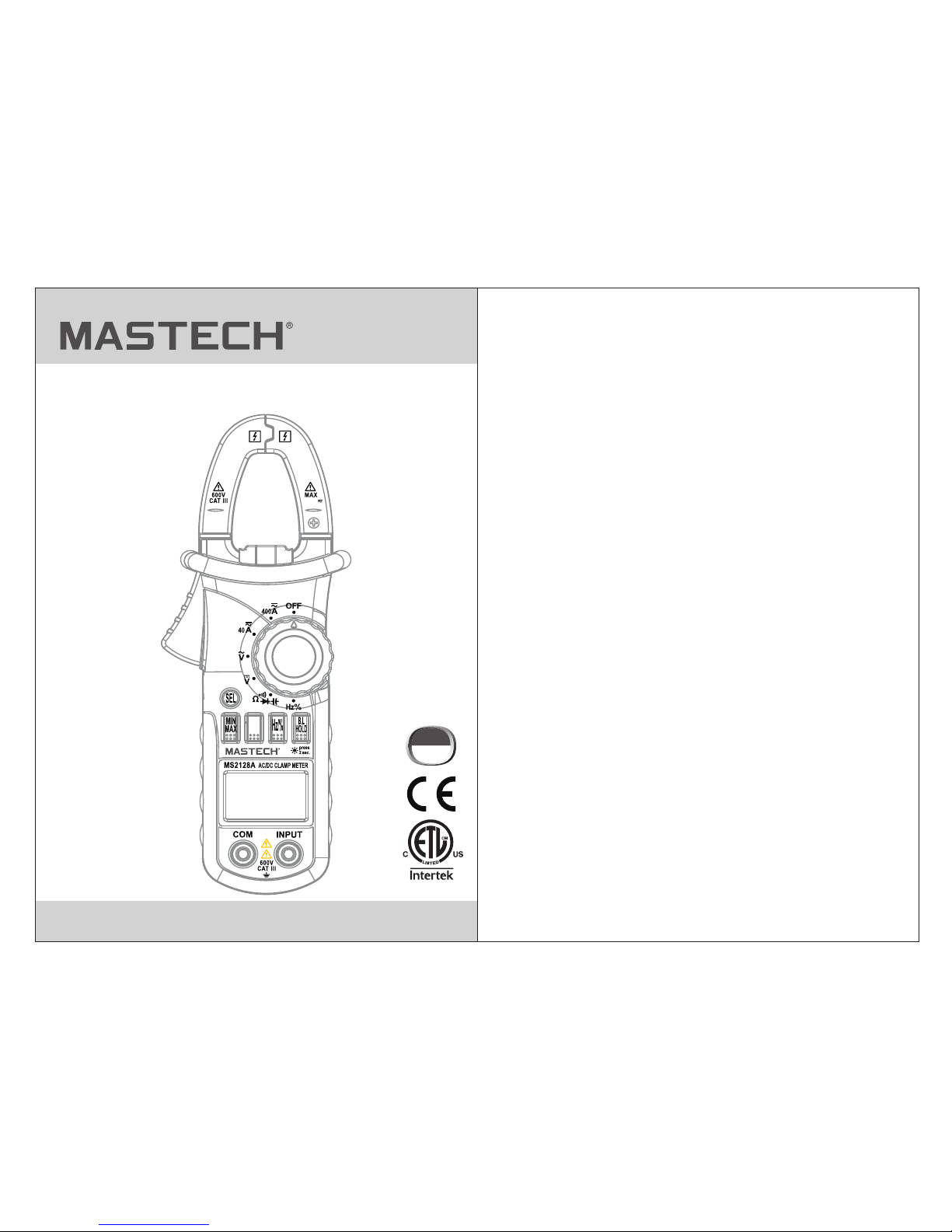
MS2128A
DIGITAL CLAMP METER
OPERATION MANUAL
CAT III
600V
400A
REL
Page 2

1.1 Preliminary
1.2 During use
1.3 Symbols............
CONTENTS CONTENTS
1. Safety Information
...............................1
............................................1
...................................2
.............................3
4
............7
...................7
..........................15
.................................15
.......................................15
................16
....................................16
....................................3
..............................17
....
..
1.4 Maintenance............
2. Description
...........................................
2.1 Names OF Parts
...................................5
2.2 Switch, Buttons And Input Jacks
2.3
3. Specifications
......................................9
4. Operation Instruction
...........................9
3.1 General Specifications
3.2 Technical Specifications
.........................9
4.1 Holding Readings
4.2 Switching Rel
4.3 Switching Frequency Or Duty
4.4 Switching Maximum Or
Minimum Value
4.5 Switching Functions
4.6 Back Light And Clamp Lighting Bulb
4.7 Auto Power Off..........................................18
4.8 Preparing For Measurement
4.9 Measuring Ac Current
4.10 Measuring Dc Current
4.11 Measuring Ac Voltage
4.12 Measuring Dc Voltage
......................18
................................19
..............................20
..............................22
..............................24
..............................26
.......................................29
.............................33
..........................................35
....................................37
...........................39
.......17
4.13 Measuring Frequency
4.14 Measuring Duty
4.15 Measuring Resistance
4.16 Testing Diode
4.17 Testing Continuity
4.18 Measuring Capacitance
5. Maintenance
...........................................41
.............................41
5.1 Replacing The Batteries
5.2 Replacing Test leads
.................................43
6. Accessories
............................................43
LCD (Liquid-Crystal Display)
Page 3

01 02
1. Safety Information
With p roper use a nd care, th is digita l multime ter will gi ve
you ye ars of sati sfactor y service .
1.1 Preliminary
1.1.1 When using the meter, the user must observe all
normal safety rules concerning:
- General protection against electric shock
- Protection of the meter against misuse.
1.1.2 When the meter is delivered, check whether it has
been damaged in transit.
1.1.3 After being stored and delivered under harsh
conditions, the meter should be checked and
confirmed whether any damages have been incurred.
1.1.4 Test leads must be kep t in good condition. Before
using check whether the insulation on tes t leads has
been damaged and any wire has been exposed.
1.1.5 Use the test leads supplied to en su re operati on
safety. If required, they must be replaced with test
leads of the same mod el or class.
1.2 During Use
1.2. 1 Use the rig ht input ja ck, funct ion and ran ge.
1.2. 2 Do not take m easurem ents that e xceed the
prot ection li mit value s indicat ed in the
spec ificati ons.
1.2. 3 Do not touc h the metal t ips of the te st leads wh en
the me ter is conn ected to th e circuit t o be
meas ured.
1.2. 4 Keep your f ingers be hind the pr obe barri ers when
taki ng a measur ement wit h an effective voltage
abov e 60V DC or 30V r ms AC.
1.2. 5 Do not take v oltage me asureme nt if the val ue
betw een the ter minals an d earth gro und excee ds
600V.
1.2. 6 Select th e highest r ange if the v alue scal e to be
meas ured in the m anual ran ge is unkno wn.
1.2.7 Disconnect the test leads from the circuit under test
before turning the rotary selector to change
functions.
1.2.8 Do not measure the resistance, capacitance, diode
or continuity of live circuits.
1.2.9 Do not connect the meter to any voltage source
while the rotary selector is in the current,
resistance, capacitance, diode or continuity range.
1.2. 10 Do not tak e capacit ance meas urement s until the
capa citor to be m easured h as been ful ly
disc harged.
Be extremely careful when using this meter. Improper use of this device
can result in electric shock or destruction of the meter. Take all normal
safety precautions and follow the safeguards suggested in this manual.
To exploit full functionality of the meter and ensure safe operation,
please read carefully and follow the directions in this manual. If the
equipment is used in a manner not specified by the manufacturer, the
protection provided by the equipment may be impaired.
WARNING
This meter is designed and manufactured according to safety
requirements of EN 61010-1, EN 61010-2-032, EN 61010-2-033
concerning electronic measuring instruments with a measurement
CAT III 600V and pollution degree 2 and safety requirements for
hand-held clamps for electrical measurement and test.
1.2.11 Do not use the meter near explosive ga se s, steam
or dirt.
1.2.12 Stop using the met er if any abnormalities or faults
are observed.
Page 4
03 04
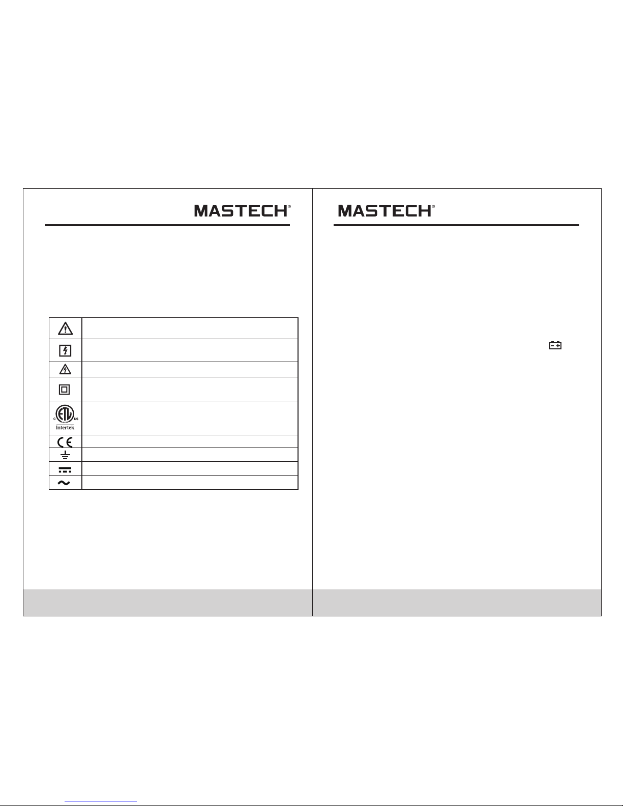
1.3 Symbols
1.4 Maintenance
1.4.1 Do not attempt to remove the rear case to adjust or
repair the meter. Such actions should only be
performed by a technician who fully understands the
meter and the danger involved.
1.4.2 Before opening the case and battery cover of the
meter, always disconnect test leads from all sources
of electric current. Disconnect the test leads from all
sources of electric current before opening the rear
case and battery cover of the meter.
1.4.3 To avoid any electric shock caused by error readings,
replace the batteries immediately when the “ ” sign
appears on the display.
1.4.4 Use damp cloth and mild detergent to clean the meter;
do not use abrasives or solvents.
1.4.5 Turn the rotary selector to OFF position to switch off
the power when the meter is not in use.
1.4.6 Remove the batteries to avoid damages to the meter
if it will idle for a long time.
2. Description
- This meter is a portable professional measuring
instrument with LCD and back light easily reading. The
'single-hand operation' design for the range switch makes
measurement simple and easy. Overload protection and
low battery indication are provided. It is an ideal multifunction instrument with scores of practical applications
for professional, workshop, school, hobby and home use.
- The meter can perform measurements of AC/DC voltage
and current, resistance, frequency, duty, capacitance, as
well as continuity and diode test.
- Both auto range and manual range are available.
- This meter is equipped with reading hold function.
- This meter is equipped with true root mean square value
measuring function (at AC A and AC V range).
1.2. 13 Do not use t he meter un less its re ar case and
batt ery cover i s securel y fastene d in its orig inal
posi tion.
1.2. 14 Do not sto re or use the m eter in are as expose d to
dire ct sunlig ht, at high t emperat ure or with h igh
rela tive humi dity.
Note -Import ant safet y informa tion, ref er to the
inst ruction m anual.
Conforms to UL STD. 61010-1, 61010-2-032,
61010-2-033; Certified to CSA STD C22.2 NO.
61010-1, 61010-2-032,61010-2-033
Comp lies with E uropean ( EU) safet y standar ds
Eart h (ground ) TE RMINAL
Caut ion, poss ibility o f electri c shock
Equi pment pro tected th roughou t by double
insu lation or r einforc ed insula tion.
Application around and removal from UNINSULATED
HAZARDOUS LIVE conductors is permitted.
Dire ct curren t
Alter nating cu rrent
CAT III : MEASU REMEN T CATEGORY III is ap plica ble to
test and me asuri ng circ uits connected to t he dist ribut ion
part of the b uildi ng's low-voltage MAINS i nstal latio n.
1.4. 1 Do not atte mpt to remo ve the rear c ase to adju st or
repa ir the mete r. Such acti ons shoul d only be
perf ormed by a te chnicia n who fully u ndersta nds
the me ter and the d anger inv olved.
Page 5
05 06
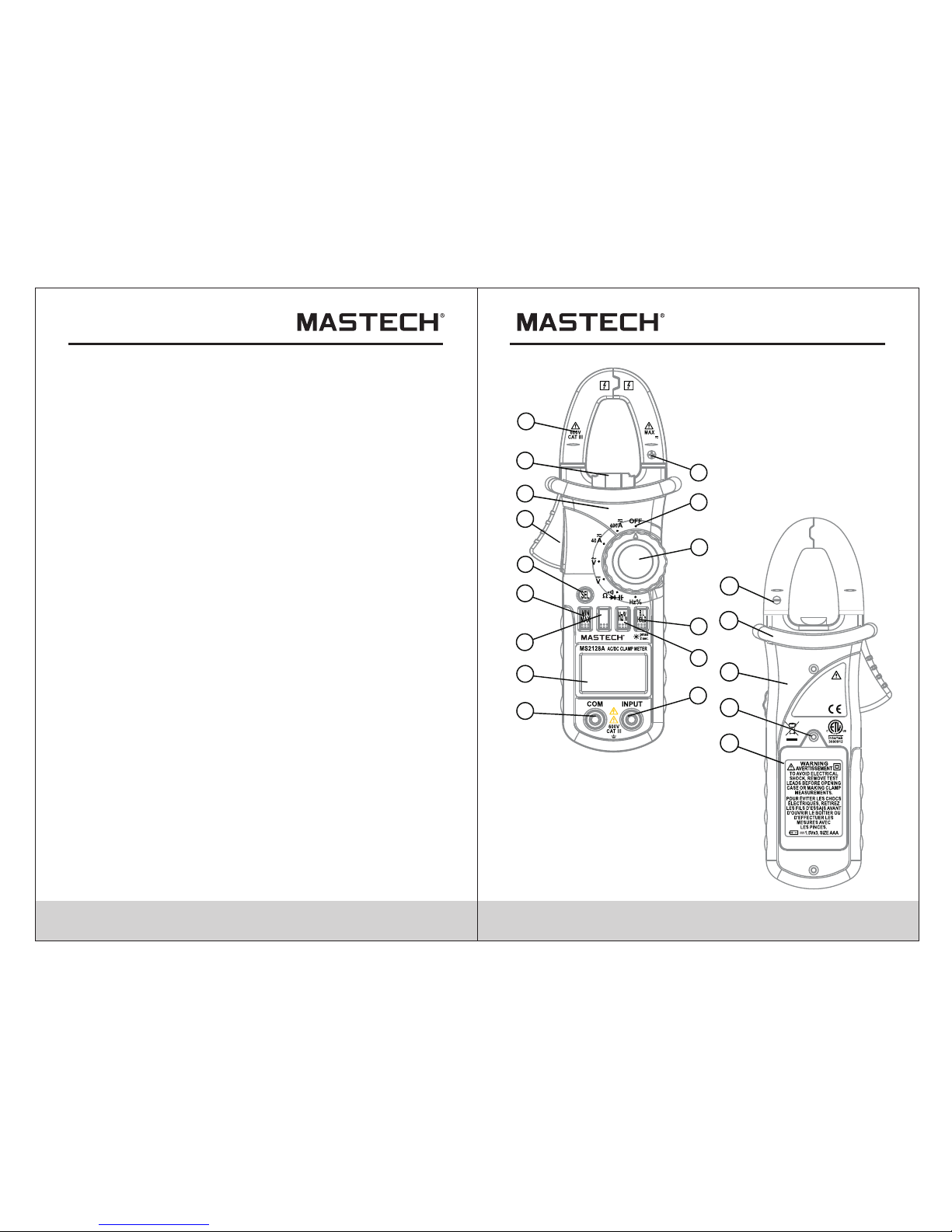
2.1 Names Of Components
(1) Cu rr en t Clamp
(2) Cl am p Li ghting Bulb
(3) Pa ne l
(4) Tri gg er
(5) Fu nc ti on Switch Butto n (S E L )
(6) MA X/ MI N Switch Button ( MA X/MIN)
(7) Re la ti ve Switch Butto n (R EL)
(8) Li qu id C rystal Displa y (L CD)
(9) CO M Ja ck
(10) I np ut J ack
(11) Hz/Duty Sw it ch Button (Hz/%)
(12) R ea di ng Hold/Back Li gh t Button (HOLD/B. L)
(13) R ot ar y selector
(14) O FF - p ow er switch
(15) “ +” S ym bol
(16) “ -” S ym bol
(17) R ea r Ca se
(18) F ix in g Screw of Batter y Co ver
(19) B at te ry Cover
(20) P ro te ctive Barrier ( to w arn the operator of t he l imit of
safe acc es s)
- This meter is equipped with inrush current measuring function.
- This meter is equipped with auto zero function (at DCA range).
- This meter is equipped with maximum value measuring
function.
- This meter is equipped with minimum value measuring function.
- This meter can measure frequency by clamp.
- This meter has function of auto power off.
- The normal function of the product may be disturbed by strong
Electro-Magnetic interference. If so, simply reset the product to
resume normal operation by following the instruction manual.
In case the function could not resume, please use the product
in other location.
1
2
3
4
5
6
7
8
9
10
11
12
13
14
15
18
17
19
16
ACCORD WITH:
IEC 61010- 2-032
IEC 61010-2 -033
CAUTION
IEC 61010-1
600V CAT III
20
400A
REL
Page 6
07 08
2.2 Switch, Buttons And Inpu t Jacks
HOLD/B.L Button
- For holding the reading or control backlight
S E L Button
- For switching among measuring functions
REL Button
- The key is the relative value measurement.
Hz/% Button
- For switching between frequency and duty measuring
functions.
MAX/MIN Button
- For switching between maximum and minimum value
measuring function.
Rotary Selector
- For selecting functions and ranges.
OFF Position
- for turning off the power.
INPUT Jack
- For measuring voltage, resistance, frequency, duty,
capacitance, diode, and continuity.
COM Jack
- Common input connection for current, voltage, resistance,
frequency, duty, capacitance, diode, continuity
measurement.
Clamp
- For measuring current
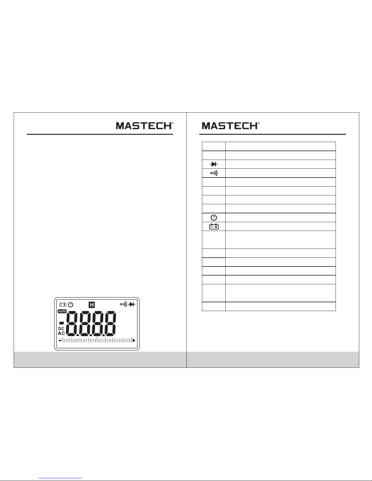
2.3 LCD (Liquid-crystal displa y)
AC
Alternating current
Direct current
Diode test
Continuity buzzer
Auto range mode
The minimum value is being measured.
The mimum value is being measured.
AUTO
MAX
MIN
DC
REL
H
%
mV, V
A
Ω, kΩ,
MΩ
Hz, kH z
nF,μF
Auto power off
Battery low
This indicates that the display data is
being held.
Percent (Duty cycle)
Milli-volts, Volts (Voltage)
Amperes (Current)
Nanofarad, Microfarad
Ohms, Kilo-ohms, Mega-ohms
(Resistance)
Hertz, Kilo-hertz (Frequency), Milohertz
DCA zero and relative measure
40
3020100
MkΩ
Hz
mVA
nμF
%
MAX MIN
REL
Page 7
09 10
3. Specifications
Calibration is required once a year, to be carried out at
a temperature between 18°C and 28°C (64F° to 82F°)
and relative humidity below 75%.
3.1 General Specifications
3.1.1 Auto range.
3.1.2 Over range protection is provided for all ranges.
3.1.3 Maximum voltage between terminals and earth
ground: 600V DC or 600 rms AC
3.1.4 Operating altitude: max. 2000 meters (7000 ft.)
3.1.5 Display: 4000 counts with analog bar LCD display
3.1.6 Maximum value display: 4000 digits
3.1.7 Polarity indication: automatic; ‘-’ for negative
polarity.
3.1.8 Over range indication: ‘0L’ or ‘-0L’
3.1.9 Converter Rate: 3 times/sec; Bar graph: 30 times/sec.
3.1.10 Unit indication: function and unit.
3.1.11 Auto power off time: 15 minute.
3.1.12 Operating power : 3× 1.5V AAA batteries
3.1.13 Battery low indication: ‘ ’ on LCD
3.1.14 Temperature factor: < 0.1×Accuracy /°C
3.1.15 Operating temperature: 0°C to 40°C(32°F to 104°F)
3.1.16 Storage temperature: -10°C to 50°C(10°F to 122°F)
3.1.17 Dimension: 208×78×35mm
3.1.18 Weight: approximate 340g(including batteries)
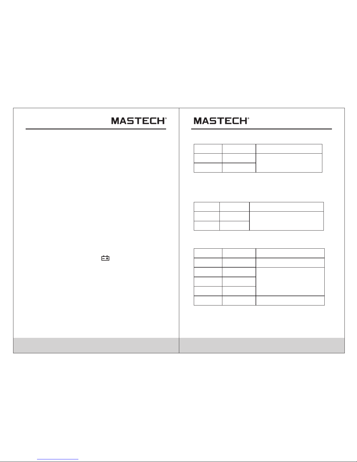
3.2 Electrical Specifications
Ambient temperature: 23±5°C
Relative humidity: < 75%
3.2. 1 AC Current
±(2.0% of rdg + 6 digits)
Accu racy
Reso lution
0.01 A
0.1A
Rang e
40A
400A
- Max. i nput curr ent: 400A AC
- Freq uency ran ge: 40 to 400 Hz
- Resp onse: Averag e value
3.2. 2 DC Curren t
- Max. i nput curr ent: 400A DC
±(2.0% of rdg + 6 digits)
Accu racy
Reso lution
0.01 A
0.1A
Rang e
40A
400A
3.2. 3 DC Voltage
Accu racy
Reso lution
0.1m V
0.00 1V
Rang e
400m V
4V
0.01 V
40V
±(1. 0% of r dg + 2d igits)
0.1V
400V
±(0. 7% of r dg + 2d igits)
- Inpu t impedan ce: 10MΩ
- Max. i nput volt age: 600V D C
1V
600V
±(0. 8% of r dg + 2d igits)
Page 8
11 12
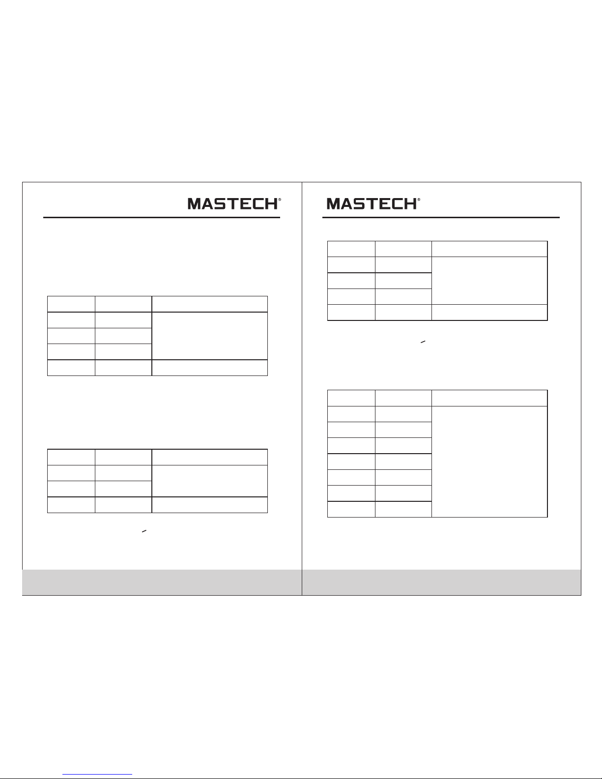
3.2. 4 AC Voltage
Accu racy
Reso lution
0.00 1V
0.01 V
Rang e
4V
40V
0.1V
40 0V
1V
600V
±(0. 8% of r dg + 3d igits)
±(1% of rdg + 4digi ts)
- Inpu t impedan ce: 10MΩ
- Max. i nput volt age: 600V r ms AC
- Freq uency ran ge: 40 to 400 Hz
- Resp onse: Averag e value
3.2. 5 Frequen cy
3.2. 5.1 By A range ( f rom curre nt clamp) :
±(1. 5% of r dg + 5 digits)
Accu racy
Reso lution
0.1H z
Rang e
10Hz
1kHz
0.00 11k Hz
0.00 11k Hz
>1kH z
- Meas urement r ange: 10 ~ 1k Hz
- Inpu t current r ange: >40 A rms AC (highe r input
curr ent at high er freque ncy)
- Max. I nput curr ent: 400A rm s AC
Note:
At sma ll voltag e range, un steady re adings wi ll appear
befo re the test l eads cont act the cir cuit. This is normal
beca use the met er is highl y sensiti ve. When th e test
lead s contact t he circui t, the true r eading wi ll be shown .
3.2. 5.2 By ACV ran ge:
Accu racy
Reso lution
0.01 Hz
0.00 1kHz
Rang e
10Hz
1kHz
0.01 kHz 10 kHz
>10k Hz
±(1. 5% of r dg + 5 digits)
- Meas urement r ange: 10 ~ 10 kHz
- Inpu t voltage r ange:>0 .6V rms AC (hi gher inpu t
volt age at high er freque ncy)
- Inpu t impedan ce: 10MΩ
- Max. i nput volt age: 600V r ms
0.01 kHz
3.2. 5.3 By Hz/D UTY range
Accu racy
Reso lution
0.00 1Hz
0.01 Hz
Rang e
9.99 9Hz
99.9 9Hz
0.1H z 999.9Hz
9.99 9kHz
±(0. 5% of r dg + 3 digits)
- MAX. I nput volt age:600 V AC (rms)
0.00 1kHz
99.9 9kHz
999. 9kHz
9.99 9MHz 0.00 1MHz
0.1k Hz
0.01 kHz
Take i t only as refe rance
Take i t only as refe rance
Page 9

13 14
Accu racy
Reso lution
0.1Ω
0.00 1kΩ
Rang e
400Ω
4kΩ
0.01 kΩ 40 KΩ
0.1k Ω400k Ω
±(0. 8% of r dg +3di gits)
0.00 1MkΩ
4MΩ
0.01 MΩ
40MΩ
- Open c ircuit vo ltage: 0. 23V
3.2. 7 Resista nce
±(1. 2% of r dg + 3d igits)
3.2. 8 Diode
Func tionReso lution
Rang e
Disp laying approximate
for ward voltage of di ode
0.00 1V
- Forw ard DC curr ent~1mA
- Reve rsed DC vol tage~3. 0V
Reso lution
Rang e
Buil t-in bu zzer wi ll soun d,
if r esistan ce is l ower th an
50±2 0Ω.
0.1Ω
- Open c ircuit vo ltage~0 .4V
3.2. 9 Continu ity
3.2. 6 Duty Cycl e
Accu racy
Reso lution
0.1%
Rang e
1.0% - 99.9%
±3.0 %
3.2. 6.1 By A range ( f rom curre nt clamp) :
- Freq uency res ponse: 10 ~ 1kHz
- Inpu t current r ange:> 4A rm s AC
- Max. i nput curr ent: 400A
3.2. 6.2 By ACV ran ge:
- Freq uency res ponse: 10 ~ 1 0 kHz
- Inpu t voltage r ange:>1 V rms AC
- Inpu t impedan ce: 10MΩ
- Max. i nput volt age: 750V r msAC
3.2. 6.3 By Hz/D UTY range
- Freq uency res ponse: 1 ~ 10 M Hz
- Inpu t voltage r ange:>5 00mV rms
3.2. 10 Capaci tance
Accu racy
Reso lution
0.01 nF
Rang e
40nF
400n F
4µ F
0.01 µF40µF
±(4. 0% of r dg + 5 digits)
0.1µ F
400µ F
0.1n F
0.00 1µF
4000 µF 1µF
Func tion
Page 10

15 16
4. Operation Instruction
4.1 Holding Readings
4.1. 1 Press the “ HOLD/B. L” button t o hold the re adings
whil e taking me asureme nt and the va lue on the
disp lay will be h eld.
4.1. 2 Press the “ HOLD/B. L” button a gain to rel ease
the re ading hol d functio n.
4.2 Switching Rel
1) REL key is the relative va lue measu rement
comm unicati on transm ission ke y that acts w ith
trig ger. Press t his key wil l enter int o the relat ive
valu e measure ment mode . Th e system wi ll save the
disp lay value i n the memor y as the refe rence val ue.
When d oing the me asureme nt later, th e display
valu e will be the d ifference v alue that t he entry
valu e deducts t he refere nce value .
2) Pre ss REL key w ill enter i nto the Man ual
Meas urement M ode autom aticall y.
3) In RE L measur ement sta tus, pres s the key aga in,
the RE L functi on will be re locked.
4) Pre ss the key in H OLD statu s, HOLD fun ction wil l be
canc elled. The sy stem will s ave the dis play valu e in
the me mory as the r eferenc e value. Wh en doing th e
meas urement l ater, the di splay val ue is the
differ ence that t he entry va lue deduc ts the
refe rence val ue.
5) Pre ss SELECT Key o r use Mode Sw itch will c ancel
REL measurem ent mode, a nd go back to t he
norm al mode (RE L will dis appear in t he LCD).
6) OL triggering: Under REL mod e, OL show s when
inpu t value lar ger than th e allowed v alue of the
meas urement m ode. Pres s the key aga in, the
rela tive meas urement f unction w ill be canc elled.
Disa ble to ente r REL mode w hen OL shows.
7) No an alog sect ion bar fun ction und er REL mod e.
4.3 Switching Frequency Or Duty
4.3. 1 During wo rking at th e voltage o r current r anges,
pres s the “Hz/% ” button on e time, fre quency of
the vo ltage or cu rrent wil l be measur ed.Pres s the
“Hz/ %” button t wice, the m eter will b e changed
into t he duty ran ge for meas uring the d uty cycle
of the v oltage or c urrent. At t he same tim e, the
mete r is change d into manu al mode.
4.3. 2 Press the “ Hz/%” but ton again , meter wil l be
back t o the condi tion of the v oltage or c urrent
meas uring.
Note:
Duri ng workin g at maximu m or minimu m value
meas uring fun ction, th e meter can 't be chang ed into
freq uency or du ty cycle me asuring m ode.
4.4 Switching Maximum Or Minimum Va lue
4.4. 1 press the m axim/mi nimum but ton to ente r into
the ma ximum mod e, the maxi mum will al ways be
meas ured. and p ress this b utton aga in, it is the
same w ith the min imum.
4.4. 2 After ente ring into m aximum/ minimum m ode,
ther e is no more an alog func tion and au to power
off func tion will a lso be canceled too.
4.4. 3 After ente ring into m aximum/ minimum m ode,
the ma ximum/m inimum da ta will be re corded
auto matical ly.
4.4. 4 Press the m ax/min bu tton for mo re than 2
seco nds, it wil l be set into t he normal m ode.
Page 11

- LED, w hich requ ires a larg er workin g current , is the
main s ource of ba ck light. Al though th e meter is
equi pped with a t imer set at 1 5 seconds ( i.e. the ba ck
ligh t will be off aut omatica lly after 3 0 seconds ),
freq uent use of t he back lig ht will sho rten the li fe of
the ba tteries . Th erefore , do not use the back light
unle ss necess ary.
- When t he batter y voltage i s<3.7V, the symbol “ ”
(bat tery low) will appe ar on the LCD . When the ba ck
ligh t is on, even i f the batte r is>3.7V, the “ ” may
appe ar becaus e of its larg e working c urrent wh ich
will c ause the vo ltage to dr op. (The ac curacy
of the m easurem ent canno t be assure d when the
“ “ symb ol appear s.) In this c ase, you ne ed not
repl ace the bat teries ye t. Normal ly, the batteries
can la st until th e “ ” appears w hen the bac k light is
not be ing used.
17 18
1) Dur ing measu ring maxi mum or mini mum value , the
mete r will be set t o manual mo de automa tically.
2) Dur ing worki ng at frequ ency or dut y measuri ng
func tion, the m eter can' t be change d into maxi mum
or min imum valu e measuri ng mode.
Note:
4.5 Switching Functions
1) SEL ECT Key is a func tion sele ction key t hat acts
with t rigger. Pr ess the key c an choose t he needed
meas urement m ode: To choo se DC or AC in DC/ AC
stat us, to choo se Diode or B uzzer in Di ode/Buz zer
stat us, to choo se Ohm, Cap , Diode or Bu zzer in
Ohm/ Cap/Dio de/ Buzze r status.
2) Pre ss the key th en turn on th e power, the Au to
Powe r-off funct ion will be c ancelle d, the sign al
"APO "disapp ears in LCD , and enter i nto Sleep
Stat us (Power -Off). Press the key then power on
will h ave the Auto P ower-Off fu nction.
4.6 Back Light And Clamp Light ing Bulb
4.6. 1 Press the “ HOLD/B. L” button f or two or mor e
seco nds to swit ch on the bac k light if th e light
in the e nvironm ent is too di m for takin g reading ,
whic h will last f or 15 secon ds.
4.6. 2 During th e back ligh t is workin g, press th e
“HOL D/B.L” bu tton for tw o or more sec onds, it
will b e turned off.
4.6. 3 At the curre nt range, w hen the bac k light is
swit ched on, th e clamp lig hting bul b will be tur ned
on at th e same time .
Note:
4.7 Auto Power Off
4.7. 1 If the mode s witch or ke ys of the met er is no
acti on within 1 5 minutes , the syste m will powe r
off auto matical ly (sleep mode). In Auto
Powe r-off status, press any key, th e meter wil l
"Aut o Power-O n" (Opera tion Mode )
4.8 Preparating For Measurement
4.8. 1 Switch on the powe r by turn ing the rotary sele ctor.
If the battery voltage is lower than 3.7V, the “ ”
sym bol will appear and the batt eries should be
rep laced.
4.8. 2 The “ ” symb ol shows th at the in put voltage or
cur rent should not exc eed the specifie d value in
ord er to prote ct the in ternal circuit from damage .
Page 12

19
4.9 Measuring AC Current
WARNI NG
Bewa re of Elect rocutio n.
Ensu re that the t est leads a re discon nected
from t he meter be fore maki ng curren t clamp
meas urement s.
4.9. 1 Set the rotary sel ector to the 40A or 40 0A ran ge
pos ition.
4.9. 2 push th e REL key make sur e the LCD display ze ro
if the unstead y readin g appear before
mea suremen t.
4.9. 3 Press the trigger to open jaw. Fully enclose on ly
one conductor.
4.9. 4 Take the read ing on th e LCD.
Note:
1) Do not put more than one cable into
the jaw dur ing te st, ot herwise incor rect
test value might be obt ained.
2) For optimum resul ts, ce nter the con ductor in the ja w.
3) At the manu al ran ge mod e, whe n only ‘O L’ is shown
on the LCD, it means the mea suremen t has
exceeded the range . A hi gher range should
be selected.
4.8. 3 Turn the rotary sel ector to the required funct ion
and range to be measure d.
4.8. 4 Connec t the common test le ad first and then th e
cha rged test leads whe n making connect ion.
Take away the char ged test lead first when
dis connect ing.
4) If the sca le of the value to be measu red is unkno wn
beforeha nd, set the rang e to the hi ghest.
4.10 Measuring DC Current
WARNI NG
Bewa re of Elect rocutio n.
Ensu re that the t est leads a re discon nected
from t he meter be fore maki ng curren t clamp
meas urement s.
4.10 .1 Set th e rotary se lector to the 40A or 400A ran ge
pos ition.
4.10 .2 Press the SEL key turn to DC cu rrent
mea suremen t mode..
4.10 .3 Press the "REL" button, the meter will be set
to zero.
4.10 .4 Press the trigger to open jaw. Full y enclose only
one conductor.
4.10 .5 Take th e reading on the LCD .
4.10 .6 Symbo l "-" will be displa yed on LC D if the
dir ection of the curre nt is neg ative.
Note:
1) Do not put more than one cable into the jaw durin g
test, otherwise incorrect test value might be obtained.
2) For optimum resul ts, pr ess th e "REL " butt on to make
the meter get int o zero first .
3) For optimum resul ts, ce nter the con ductor in the ja w.
4) At the manu al ran ge mod e, whe n only “O L” or “-O L”
is shown on the LCD, it means the meas urement has
exceeded the range . A hi gher range should be selected .
5) Under the manual range mode, when the scale of the
value to be measu red is unkno wn beforehand, set
the range to the highes t.
20
5) “ ” means the maximum input curren t is
400A rms AC.
6) " " means the maximum input curren t is 400A DC.
Page 13

21 22
4.11 Measuring AC Voltage
WARNI NG
Bewa re of Elect rocutio n. Pay spec ial atten tion to
avoi d electri c shock whe n measuri ng high vol tage.
Do not i nput the vo ltage whi ch more tha n750V rms
AC.
4.11.1 Plug the black test lead into the COM jack and the
red test lead into the INPUT jack.
4.11.2 Set the rotary selector to position to make the
meter get into AC V range.
4.11.3 Connect the test leads to the voltage source or load
terminals for measurement.
4.11.4 Take the reading on the LCD.
Note:
1) “ ” means the maxim um input voltage is 750V True
RMS AC.
2) If the test result is mor e than 750V True RMS AC,
symbol “OL” will be dis played on LCD and the build-up
buzzer will sound .
V
Correct Incorrect
400A
REL
REL
REL
Page 14

9V
23 24
4.12 Measuring DC Voltage
WARNI NG
Bewa re of Elect rocutio n.
Pay sp ecial att ention to a void elec tric shoc k
when m easurin g high volt age.
Do not i nput the vo ltage whi ch more tha n
1000 V DC.
4.12 .1 Plug the b lack test l ead into th e COM jack an d
the re d test lead i nto the INP UT jack.
4.12 .2 Set the ro tary sele ctor to at th e V range
posi tion.
4.12 .3 Connec t the test le ads to the vo ltage sou rce or
load t erminal s for measu rement.
4.12 .4Take the re ading on th e LCD. The pola rity
symb ol denote s the polar ity of the en d
conn ected by th e red test le ad.
Note:
1) At sma ll voltag e range, un steady re adings wi ll
appe ar before t he test lea ds contac t the circu it.
This is no rmal beca use the met er is highl y sensiti ve.
When t he test lea ds contac t the circu it, the tru e
read ing will be s hown.
2) “ ” mea ns the maxi mum input v oltage is 1 000V DC.
3) If th e test resu lt is more th an 1000V DC , symbol “O L ”
will b e display ed on LCD and t he build- up buzzer
will s ound.
400A
REL
Page 15

25 26
4.13 Measuring Frequency
4.13 .1 By A range (fro m current c lamp):
WARNI NG
Bewa re of Elect rocutio n.
Ensu re that the t est leads a re discon nected
from t he meter be fore maki ng curren t clamp
meas urement s.
4.13 .1.1 Set the rotary selecto r to the A r ange
(A~ or A ) pos ition.
4.13 .1.2 Pre ss the trigger to op en jaw. Fully enclose
onl y one condu ctor.
4.13 .1.3 Pre ss the “Hz/%” to swi tch to the frequenc y
measurement.
4.13 .1.4 Take the reading on the LCD.
Note:
1) Do not put mor e than on e cable into the jaw during
tes t, otherwise incor rect tes t value might be obt ained.
2) Fr equency test range is 10Hz - 1kHz .‘00.0’ will be
dis played on LCD if the test frequ ency is lower tha n
10. 0 Hz. It is possible to test the frequen cy which is
hig her than 1 kHz but th e tolerance of the test result
can not be ensu re.
3) “ ” means the maximum input current is
400 A rms A C.
Correct Incorrect
REL
REL
Page 16

27 28
4.13 .2 By V range :
WARNI NG
Bewa re of Elect rocutio n.
Pay sp ecial att ention to a void elec tric shoc k
when m easurin g high volt age.
Do not i nput the vo ltage whi ch more tha n
750V r ms AC.
4.13 .2.1 Plu g the black test lea d into the COM jack
and the red tes t lead in to the INPU T jack.
4.13 .2.2 Set the rotary selecto r to the V r ange
pos ition.
4.13 .2.3 Pre ss the "Hz/%" to swi tch to frequency
mea suremen t.
4.13 .2.4 Con nect tes t leads to the two ends of the
sou rce or load for meas urement .
4.13 .2.5 Take the reading on the LCD.
Note:
1) Fr equency test range is 10Hz -10kHz. It is possib le
to test the fre quency which is higher than 10kHz bu t
the toleran ce of the te st resul t
can not be ensu re.
2) “ ” mean s the maxim um input voltage is
750 V rms AC.
4.13 .3 By HZ/DU TY range:
WARNI NG
Bewa re of Elect rocutio n.
Pay sp ecial att ention to a void elec tric shoc k
when m easurin g high volt age.
Do not i nput the vo ltage whi ch more tha n
250V r ms AC.
4.13 .3.1 Plu g the black test lea d into the COM jack and
the red test le ad into the INPUT ja ck.
4.13 .3.2 Set the rotary selecto r to the HZ/DUTY
ran ge position.
4.13 .3.3 Con nect tes t leads to the two ends of the
sou rce or load for meas urement .
4.13 .3.4 Take the reading on the LCD.
400A
REL
Page 17

29 30
4.14 Measuring Duty
4.14 .1 By A range ( from c urrent cl amp):
WARNI NG
Bewa re of Elect rocutio n.
Ensu re that the t est leads a re discon nected
from t he meter be fore maki ng curren t clamp
meas urement s.
4.14 . 1 . 1 Set the ro t a ry selec t o r t o the A range pos i t i o n.
4.14 . 1 . 2 Press th e t r igger to o p e n jaw. Fully en c l o s e
onl y o n e conduc t o r.
4.14 . 1 . 3 Press th e " H z/%" to sw i t c h to the D U T Y
mea s u r e ment.
4.14 . 1 . 4 Tak e t h e reading o n t he LCD.
Note:
1) Do not p ut mo r e tha n one cable into th e jaw d urin g
tes t, oth erwis e inc o rrec t test v alue m ight be obt ained .
2) If the d uty cy cle is less than 10%, sy mbol ' UL' wi ll be
dis playe d on LC D; if t he du t y cyc l e is more th an 94 . 9%,
sym bol 'O L' wi l l be di spla y ed on LCD.
3) The in put si gnal f requ e ncy ra nge is 10 – 1kHz. It is
po ssibl e to te st du t y cyc l e of the hig her th an 1 kH z
fr equen cy si g nal, b ut th e tole r ance o f the test r esul t
ca n not b e ens u re.
4) “ ” m e ans th e max imum input curre n t is 40 0A rms
AC.
Correct Incorrect
REL
REL
Page 18

31 32
4.14 .2 By V range :
WARNI NG
Bewa re of Elect rocutio n.
Pay sp ecial att ention to a void elec tric shoc k
when m easurin g high volt age.
Do not i nput the vo ltage whi ch more tha n
750V r ms AC.
4.14 .2.1 Plu g the black test lea d into the COM jack and
the red test le ad into the INPUT ja ck.
4.14 .2.2 Set the rotary selecto r to the V r ange pos ition.
4.14 .2.3 Pre ss the "Hz/%" to swi tch to DUTY
mea suremen t.
4.14 .2.4 Con nect tes t leads to the two end of the sou rce
or load for mea suremen t.
4.14 .2.5 Take the reading on the LCD.
Note:
1) If the duty cy cle is le ss than 10%, symbol 'UL' wil l be
dis played on LCD; if th e duty cycle is more than
94. 9%, symb ol 'O L' wil l be disp layed on LC D.
3) The input signa l freque ncy rang e is 10 – 10 kHz. It is
pos sible to test duty cycle of the higher than 10 kH z
fre quency signal, but the tole rance of the test re sult
can not be ensu re.
3) “ ” mean s the maxim um input voltage is
750 V rms AC.
400A
REL
Page 19

33 34
4.15 Measuring Resistance
WARNI NG
Bewa re of Elect rocutio n.
When m easurin g in-circ uit resis tance, ma ke
sure t hat the pow er of the cir cuit unde r test
has be en turned o ff and that a ll capaci tors
have b een fully d ischarg ed.
4.15 .1 Plug the black te st lead into the COM jack and the
red test lead into the INPUT jack.
4.15 .2 Set th e rotary se lector to the range positio n to
mak e the meter get into range.
4.15 .3 Conne ct the test leads to the ends of the resi stor
or circuit for measure ment.
4.15 .4 Take th e reading on the LCD .
Note:
1) Wh en the input is open , “O L”wi ll appear on the LCD to
ind icate th at the rang e has bee n exceeded.
2) Fo r measur ing resistance abo ve 1MΩ, t may take a
few seconds to get a ste ady reading. This is normal for
hig h resist ance reading.
4.14 .3 By HZ/DU TY range:
WARNI NG
Bewa re of Elect rocutio n.
Pay sp ecial att ention to a void elec tric shoc k
when m easurin g high volt age.
Do not i nput the vo ltage whi ch more tha n
250V r ms AC.
4.14.3.1 Plug the black test lead into the COM jack and the
red test lead into the INPUT jack.
4.14.2.2 Set the rotary selector to the HZ/DUTY range
position.
4.14.2.3 Press the "Hz/%" to switch to DUTY measurement.
4.14.2.4 Connect test leads to the two end of the source or
load for measurement.
4.14.2.5 Take the reading on the LCD.
Note:
1) If the duty cy cle is le ss than 10%, symbol 'UL' wil l be
disp layed on LCD; if the duty cyc le is more than 99.9 %,
symb ol 'O L' will be disp layed on LCD.
3) The input signa l freque ncy rang e is 10 – 10 kHz. It is
poss ible to test duty cy cle of th e higher th an 10 kHz
freq uency si gnal, bu t the toler ance of the test res ult can
not be ensure .
3) “ ” mean s the maxim um input voltage is 750V rms AC.
Ω
Ω
400A
REL
Page 20

35 36
4.16 Testing Diode
4.16 .1 Plug the black te st lead into the COM jack and
the red test le ad into the INPUT ja ck.
4.16 .2 Set th e rotary se lector to the range positio n.
4.16 .3 Press the "SEL" button to switch to test.
4.16 .4 Conne ct the red test lead to the anod e and the
bla ck test lea d to the cathode of the diode for
tes ting.
4.16 .5 Take th e reading on the LCD .
Note:
1) The meter will show the approximate forwar d voltag e
dro p of the dio de.
2) Wh en the test leads ha ve been reversed or open, ‘O L’
wil l appear on the LCD.
Ω
400A
REL
Page 21

3837
4.17 Testing Continuity
WARNI NG
Bewa re of Elect rocutio n.
Make s ure that th e power of th e circuit h as
been t urned off a nd the capa citors ha ve been
full y dischar ged befor e testing t he
cont inuity of a c ircuit.
4.17 .1 Plug the black te st lead into the COM jack and
the red test le ad into the INPUT ja ck.
4.17 .2 Set th e rotary se lector to the range positio n.
4.17 .3 Press the "SEL" button to switch to continui ty
tes t.
4.17 .4 Conne ct the test leads to the two end s of the
cir cuit for me asureme nt.
4.17 .5 If the resistance of the circuit being teste d is
les s than 50±2 0Ω, the built-in buzzer wil l maybe
sou nd.
4.17 .6 Take th e reading on the LCD .
Note:
If th e test leads are ope n or the resistance of the ci rcuit
is ov er 400Ω , “ O L” will appear on the LCD.
Ω
400A
REL
Page 22

4039
4.18 Measuring Capacitance
WARNI NG
Bewa re of Elect rocutio n.
To avoid el ectric sh ock, make s ure that the
capa citors ha ve been ful ly discha rged
befo re measur ing the cap acitanc e of a
capa citor.
4.18 .1 Plug the black te st lead into the COM jack and
the red test le ad into the INPUT ja ck.
4.18 .2 Set th e rotary se lector to the range positio n.
4.18 .3 After fully discharged the capac itor, con nect
the test leads to the tw o ends of th e capaci tor
for measurement.
4.18 .4 Take th e reading on the LCD .
Note:
1. It may take so me time (about 30 se conds fo r the
400 μF and 4000μF range ) for ste ady readings when
mea suring high capacity.
2. You must push th e key "RE L" when measure les s
tha n 20 n F.
Ω
400A
REL
Page 23

4241
5. Maintenance
5.1 Replacing The Batteries
WARNI NG
To avoid el ectric sh ock, make s ure that the test
lead s have been c learly mo ve away fro m the
circ uit under m easurem ent befor e opening t he
batt ery cover o f the meter.
5.1. 1 If the sign “ ” app ears, it me ans that the
bat teries should be re placed.
5.1. 2 Loosen the fixing screw of the battery cover and
rem ove it.
5.1. 3 Replac e the exhausted bat teries with new ones.
5.1. 4 Put the battery co ver back and fix it again to its
ori gin form.
Note:
Do no t revers e the polar ity of th e batteries.
WARNI NG
Do not m ix old an d new batte ries. D o not mix
alka line, s tandard (carbon- zinc), or r echarge able
(n i- cad, ni -mh, etc) b atter ies.
Page 24

43
R-00-05-1586
5.2 Replacing Test Leads
6. Accessories
Repl ace test le ads if lead s become da maged or wo rn.
Use meet EN 61010-031 standard, rated CAT III 600V, or
better test leads.
WARNING
To avoid electric shock,make sure the probes are
disconnected from the measured circuit before removingthe
rear cover. Make sure the rear cover is tightly screwed before
using the instrument.
WARNING
Test Leads
1 pair
Operating M an ua l
1 piesce
1.5V AAA Batter y
3 pieces
1)
2)
3)
Case
1 piece
4)
 Loading...