

Page 1
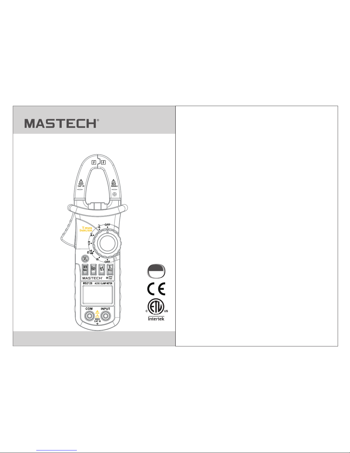
MS2128, MS2108T
DIGITAL CLAMP METER
OPERATION MANUAL
CAT III
600V
Page 2

1.1 Preliminary
1.2 During use
1.3 Symbols............
CONTENTS CONTENTS
1. Safety Information
............................1
............................................1
...................................2
.............................3
4
............7
..................................7
.......................15
.................................15
.................................15
................16
....................................16
....................................3
..............................17
...
....
..
1.4 Maintenance............
2. Description
.......................................
2.1 Names OF Parts
....................................5
2.2 Switch, Buttons And Input Jacks
2.3 Names OF Parts
3. Specifications
..................................9
4. Operation Instruction
........................9
3.1 General Specifications
3.2 Technical Specifications
......................9
4.1 Holding Readings
4.2 Switching Ranges
4.3 Switching Frequency Or Duty
4.4 Switching Maximum Or
Minimum Value
4.5 Switching Functions
4.6 Back Light And Clamp Lighting Bulb
4.7 Auto Power Off...........................................18
4.8 Preparing For Measurement
4.9 Measuring Ac Current
4.10 Measuring Inrush Current
4.11 Measuring Dc Current
4.12 Measuring Ac Voltage
4.13 Measuring Dc Voltage
........................19
..............................19
........................21
..............................23
..............................25
..............................26
..............................29
.......................................33
.............................37
..........................................39
....................................41
...........................43
.......17
4.14 Measuring Frequency
4.15 Measuring Duty
4.16 Measuring Resistance
4.17 Testing Diode
4.18 Testing Continuity
4.19 Measuring Capacitance
5. Maintenance
.......................................45
.............................45
5.1 Replacing The Batteries
5.2 Replacing Test Leads
.................................46
6. Accessories
.......................................46
Page 3

01 02
1. Safety Information
Wi th pro per use and ca re, this di gital mul time ter will gi ve
yo u year s of sat isf acto ry servic e.
1.1 Preliminary
1.1.1 When us ing the m eter, th e user mu st obse rve all
normal safe ty rule s conce rning :
- Gene ral pro tecti on agai nst ele ctric s hock
- Prot ectio n of the me ter aga inst mi suse.
1.1.2 When th e meter i s deliv ered, c heck wh ether i t has
been damaged in tran sit.
1.1.3 After be ing sto red and d elive red und er hars h
condition s, the me ter sho uld be ch ecked a nd conf irmed
whether any d amage s have be en incu rred.
1.1.4 Test leads mu st be kep t in good c ondit ion. Be fore
using check w hethe r the ins ulati on on tes t leads h as been
damaged and any wire h as been e xpose d.
1.1.5 Use the t est lea ds supp lied to e nsure o perat ion
safety. If requi red, th ey must b e repla ced wit h test le ads
of the same mod el or cla ss.
1.2 During Use
1.2.1 Use the r ight in put jac k, func tion an d range .
1.2.2 Do not ta ke meas ureme nts tha t excee d the
protectio n limit v alues i ndica ted in th e speci ficat ions.
1.2.3 Do not to uch the m etal ti ps of the t est lea ds when
the meter is co nnect ed to the c ircui t to be mea sured .
1.2.4 Keep yo ur fing ers beh ind the p robe ba rrier s when
taking a meas ureme nt with a n effecti ve volt age abo ve
60V DC or 30V rms AC .
1.2.5 Do not ta ke volt age mea surem ent if th e value
between the t ermin als and e arth gr ound ex ceeds 6 00V.
1.2.6 Selec t the hig hest ra nge if th e value s cale to b e
measured in t he manu al rang e is unkn own.
1.2.7 Disconnect the test leads from the circuit under test
before turning the rotary selector to change functions.
1.2.8 Do not measure the resistance, capacitance, diode
or continuity of live circuits.
1.2.9 Do not connect the meter to any voltage source
while the rotary selector is in the current, resistance,
capacitance, diode or continuity range.
1.2.10 Do not t ake cap acita nce mea surem ents un til the
capacitor t o be meas ured ha s been fu lly dis charg ed.
Be extremely careful when using this meter. Improper use of this device
can result in electric shock or destruction of the meter. Take all normal
safety precautions and follow the safeguards suggested in this manual.
To exploit full functionality of the meter and ensure safe operation,
please read carefully and follow the directions in this manual. If the
equipment is used in a manner not specified by the manufacturer, the
protection provided by the equipment may be impaired.
WARNING
This meter is designed and manufactured according to safety
requirements of EN 61010-1, EN 61010-2-032, EN 61010-2-033
concerning electronic measuring instruments with a measurement
CAT III 600V and pollution degree 2 and safety requirements for
hand-held clamps for electrical measurement and test.
1.2.11 Do not use the meter near explosive gases,
steam or dirt.
1.2.12 Stop using the meter if any abnormalities or faults
are observed.
1.2.13 Do not use the meter unle ss its rear case and
battery cover is securely fastened in its original position.
1.2.14 Do not store or use the meter in areas exposed to
direct sunlight, at high temperature or with high relative
humidity.
Page 4
03 04
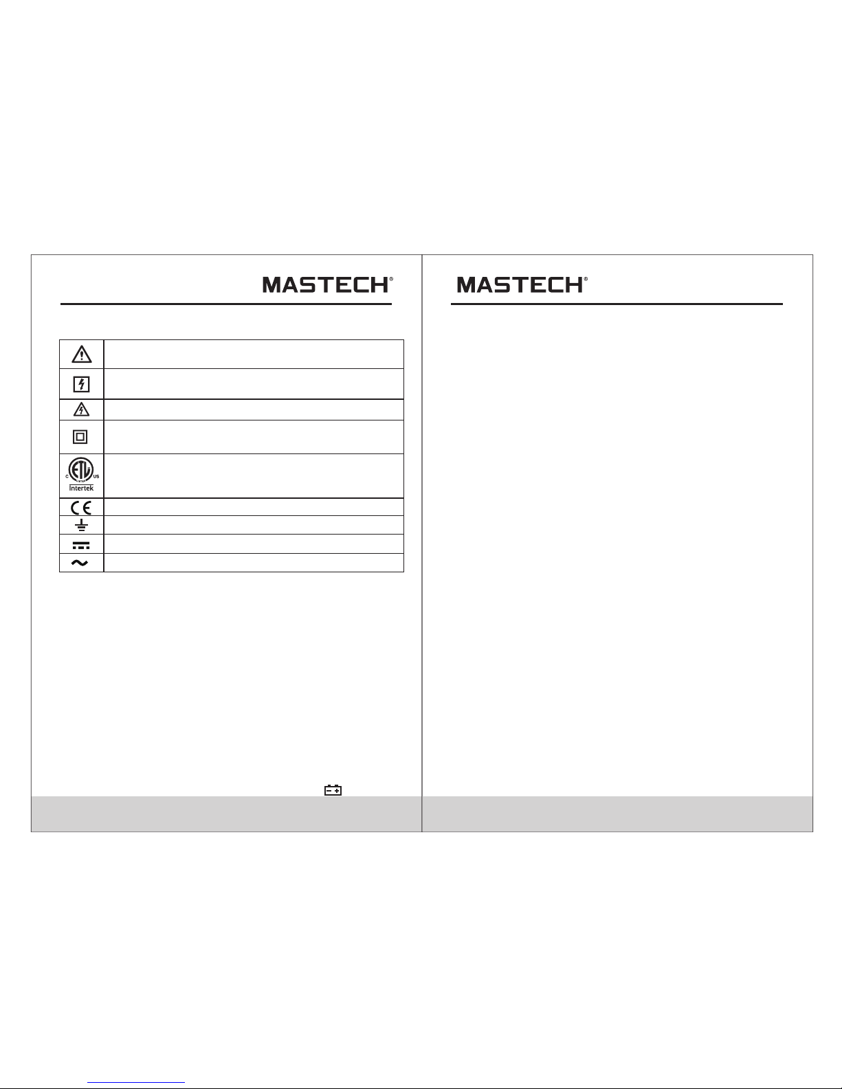
1.3 Symbols
1.4 Maintenance
1.4.1 Do not attempt to remove the rear case to adjust or
repair the meter. Such actions should only be performed
by a technician who fully understands the meter and the
danger involved.
1.4.2 Before opening the case and battery cover of the
meter, always disconnect test leads from all sources of
electric current. Discon nect the test le ads fr om all sou rces
of electric current before opening the rear case and battery
cover of the meter.
1.4.3 To avoid any electric shock caused by error readings,
replace the batteries immedi ately when the “ ” sign
appears on th e displ ay.
1.4.4 Use dam p cloth a nd mild d eterg ent to cl ean the
meter; do not u se abra sives o r solve nts.
1.4.5 Turn the r otary s elect or to OFF p ositi on to swi tch
off the power whe n the met er is not i n use.
1.4.6 Remov e the bat terie s to avoi d damag es to the
meter if it wil l idle fo r a long ti me.
2. Description
- This meter is a portable professional measuring
instrument with LCD and back light easily reading. The
'single-hand operation' design for the range switch makes
measurement simple and easy. Overload protection and
low battery indication are provided. It is an ideal multifunction Instrument with scores of practical applications for
professional, workshop, school, hobby and home use.
- The meter can perform measurements of AC/DC voltage
and current, resistance, frequency, duty, capacitance, as
well as continuity and diode test.
- Both auto range and manual range are available.
- This meter is equipped with reading hold function.
- This meter is equipped with true root mean square value
measuring function (at AC A and AC V range).
- This meter is equipped with inrush current measuring
function.
- This meter is equipped with auto zero function
(at DCA range).
- This meter is equipped with maximum value measuring
function.
- This meter is equipped with minimum value measuring
function.
- This meter can measure frequency by clamp.
- This meter has function of auto power off.
Note-Impo rtant s afety i nform ation , refer t o the
instructi on manu al.
Conforms to UL STD. 61010-1, 61010-2-032,
61010-2-033; Certified to CSA STD C22.2 NO.
61010-1, 61010-2-032,61010-2-033
Complies with Euro pean (E U) safe ty stan dards
Earth (grou nd) TERMI NAL
Caution, po ssibi lity of e lectr ic shoc k
Equipment protec ted thr ougho ut by dou ble
insulatio n or rein force d insul ation .
Application around and removal from UNINSULATED
HAZARDOUS LIVE conductors is permitted.
Direct curr ent
Alternatin g curre nt
CAT II I : M EASU REME N T CATEG ORY II I i s a ppli c able to
te s t a nd meas uring c i rcui t s conne cted to th e d istri buti o n
par t o f t he buil ding ' s l ow-v oltag e M AINS in stall atio n .
Page 5
05 06
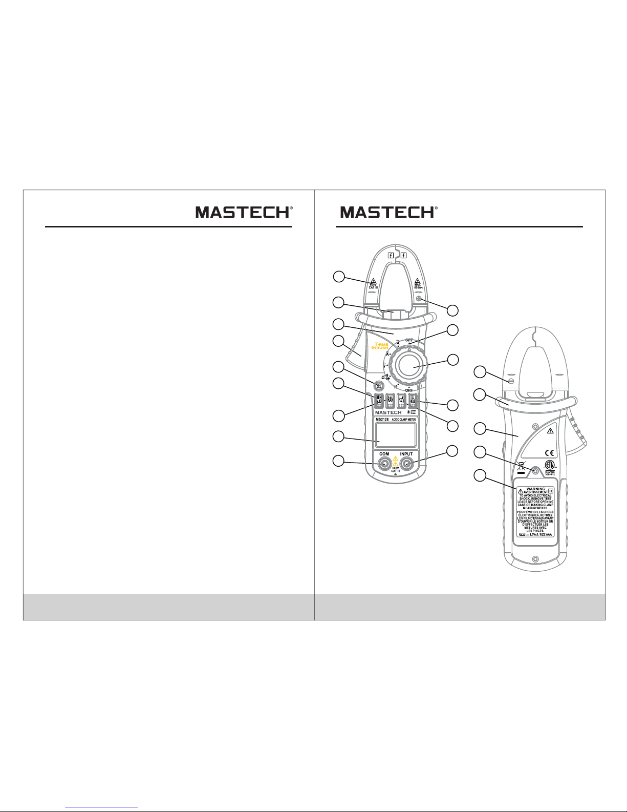
2.1 Names Of Components
(1) Current C lamp
(2) Clamp Lighting B ulb
(3) Panel
(4) Trigger
(5) Functio n Switc h Butto n (S E L)
(6) MAX/MIN S witch B utton ( MAX/M IN)
(7) Auto/Man ual Swi tch But ton (RA N)
(8) Liquid Crystal D ispla y (LCD)
(9) COM Jack
(10) Input Ja ck
(11) Hz/Duty Swi tch But ton (Hz /%)
(12) Reading Hold/ Back Li ght But ton (HO LD/B. L)
(13) Rotary s elect or
(14) OFF - powe r switc h
(15) “+” Symb ol
(16) “-” Symb ol
(17) Rear Cas e
(18) Fixing S crew of B atter y Cover
(19) Batter y Cover
(20) Protec tive Ba rrier ( to warn t he oper ator of t he limi t of
safe a ccess )
- The normal function of the product may be disturbed by strong
Electro-Magnetic interference. If so, simply reset the product to
resume normal operation by following the instruction manual.
In case the function could not resume, please use the product
in other location.
1
2
3
4
5
6
7
8
9
10
11
12
13
14
15
18
17
19
16
ACCORD WITH:
IEC 61010- 2-032
IEC 61010-2 -033
CAUTION
IEC 61010-1
600V CAT III
20
Page 6
07 08
2.2 Switch, Buttons And Input Jacks
HOLD/B.L Button
- For holding the reading or control backlight
S E L Button
- For switching among measuring functions
RAN Button
- For switching between auto and manual ranges.
Hz/% Button
- For switching between frequency and duty measuring
functions.
MAX/MIN Button
- For switching between maximum and minimum value
measuring function.
Rotary Selector
- For selecting functions and ranges.
OFF Position
- for turning off the power.
INPUT Jack
- For measuring voltage, resistance, frequency, duty,
capacitance, diode, and continuity.
COM Jack
- Common input connection for current, voltage, resistance,
frequency, duty, capacitance, diode, continuity
measurement.
Clamp
- For measuring current
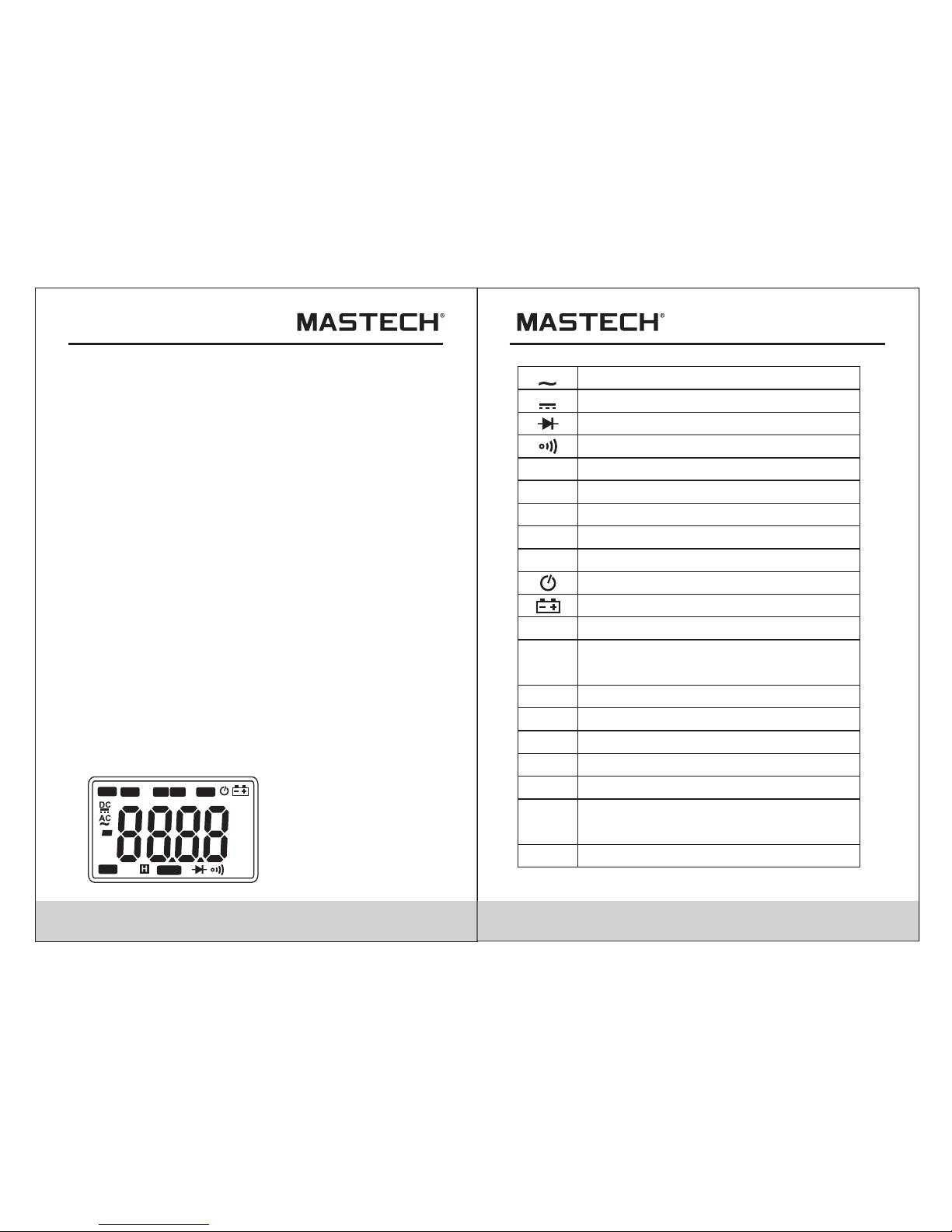
2.3 LCD (Liquid-crystal di spl ay)
AC
Alternating current
Direct current
Diode test
Continuity buzzer
Auto range mode
Manual range mode
The minimum value is being measured.
The maximum value is being measured.
AUTO
MANU
MAX
MIN
DC
ZERO
TRMS
H
INRUSH
%
mV, V
A
Ω, kΩ,
MΩ
Hz, kHz
μF, mF
DCA zero
Auto power off
Battery low
True RMS
This indicates that the display data is
being held.
Inrush current is being measured.
Percent (Duty cycle)
Milli-volts, Volts (Voltage)
Amperes (Current)
Micro-farad, Milli-farad (Capacitance)
Ohms, Kilo-ohms, Mega-ohms
(Resistance)
Hertz, Kilo-hertz (Frequency)
Hz
AUTO
MANU
MAX MIN
ZERO
°C°F%
μmVA
nμmF
MkΩ
INRU SH
TRMS
Page 7
09 10
3. Specifications
Calibration is required once a year, to be carried out at
a temperature between 18°C and 28°C (64°F to 82°F)
and relative humidity below 75%.
3.1 General Specificatio ns
3.1.1 Auto range and manual range options are available.
3.1.2 Over range protection is provided for all ranges.
3.1.3 Maximum voltage between terminals and earth
ground: 600V DC or True RMS AC
3.1.4 Operating altitude: max. 2000 meters (7000 ft.)
3.1.5 Display: LCD
3.1.6 Maximum value display: 6599 digits for MS2128
6599 digits for MS2108T
3.1.7 Polarity indication: automatic; ‘-’ for negative polarity.
3.1.8 Over range indication: ‘0L’ or ‘-0L’
3.1.9 Sampling Time: approx. 0.4 second per sample
3.1.10 Unit indication: function and unit.
3.1.11 Auto power off time: 30 min.
3.1.12 Operating power : 1.5V×3 AAA batteries
3.1.13 Battery low indication: ‘ ’ on LCD
3.1.14 Temperature factor: < 0.1×Accuracy /°C
3.1.15 Operating temperature: 0°C to 40°C(32°F to 104°F)
3.1.16 Storage temperature: -10°C to 50°C(10°F to 122°F)
3.1.17 Dimension: 208×78×35mm
3.1.18 Weight: approximate 340g(including batteries)
3.2 Electrical Specif ica tio ns
Ambient temperature: 23±5°C Relative humidity: < 75%
3.2.1 TRUE RMS
3.2.1.1 For measuring non-sinusoidal waveforms, test
error which is occurred by using True RMS
measurement techniques is less than by using
traditional average-reading techniques.
3.2.1.2 Both sinusoidal and non-sinusoidal waveforms
can be tested by True RMS Clamp Meter exactly.
At AC A & AC V ranges, even short two test probes
there are still1-50 digits might be displayed on
LCD. This is normal. Test result will not be affected.
3.2.1.3 At AC A and AC V range, True RMS value can be
tested only when input signal is more than 2% of
full range.
3.2.1.4 To ensure the precision of test result, input signal
should be:
AC voltage: > 13 mV
AC current: > 1.3A
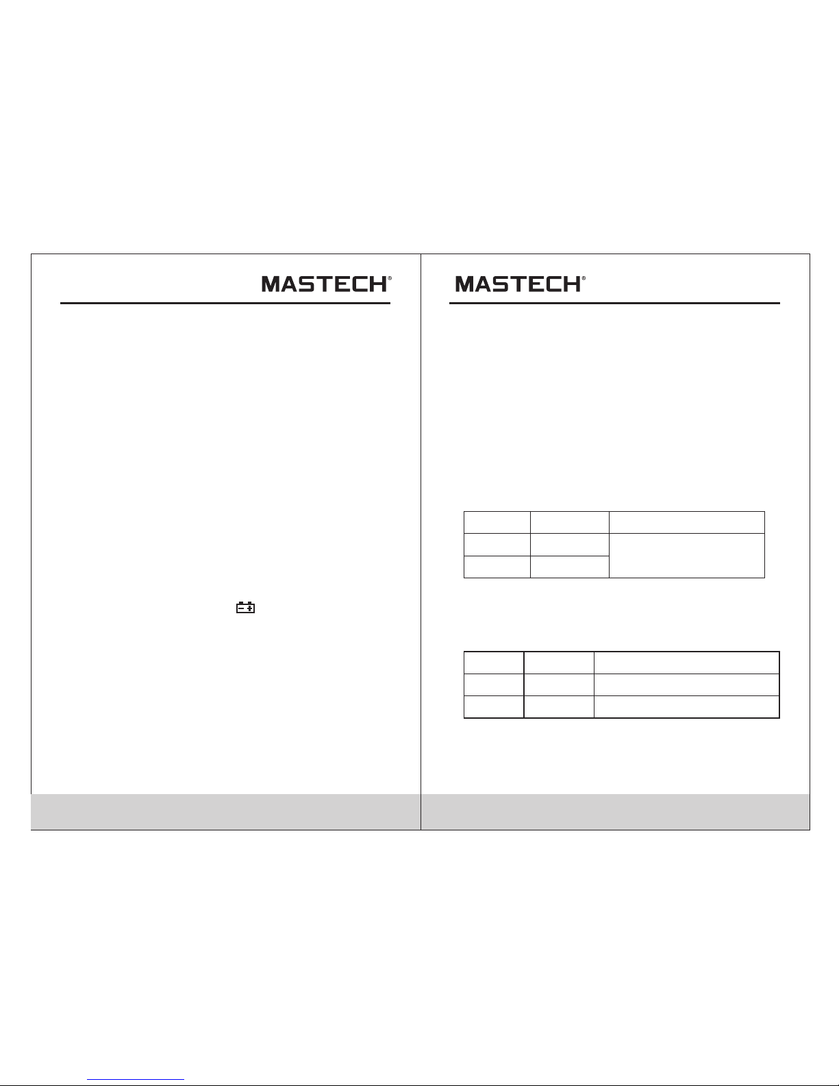
3.2.2 AC Cur rent
±(3.0% of rdg + 10 digits)
Accuracy
Resolutio n
0.01A
0.1A
Range
66A
600A
- Max. input cu rrent : 600A
- Frequency r ange: 4 0 to 400H z
- Response: t rue roo t mean sq uare va lue
3.2.3 Inrus h Curre nt
±(10.0% of rdg + 60 digits)
Accuracy
<60A take it only as refe rance
Resolutio n
0.01A
0.1A
Range
66A
600A
- Integrati on Time: 1 00ms
- Measureme nt rang e: 30 ~ 600 A
- Max. input cu rrent : 600A
- Frequency r ange: 4 0 to 400H z
- Response: t rue roo t mean sq uare va lue
Page 8
11 12
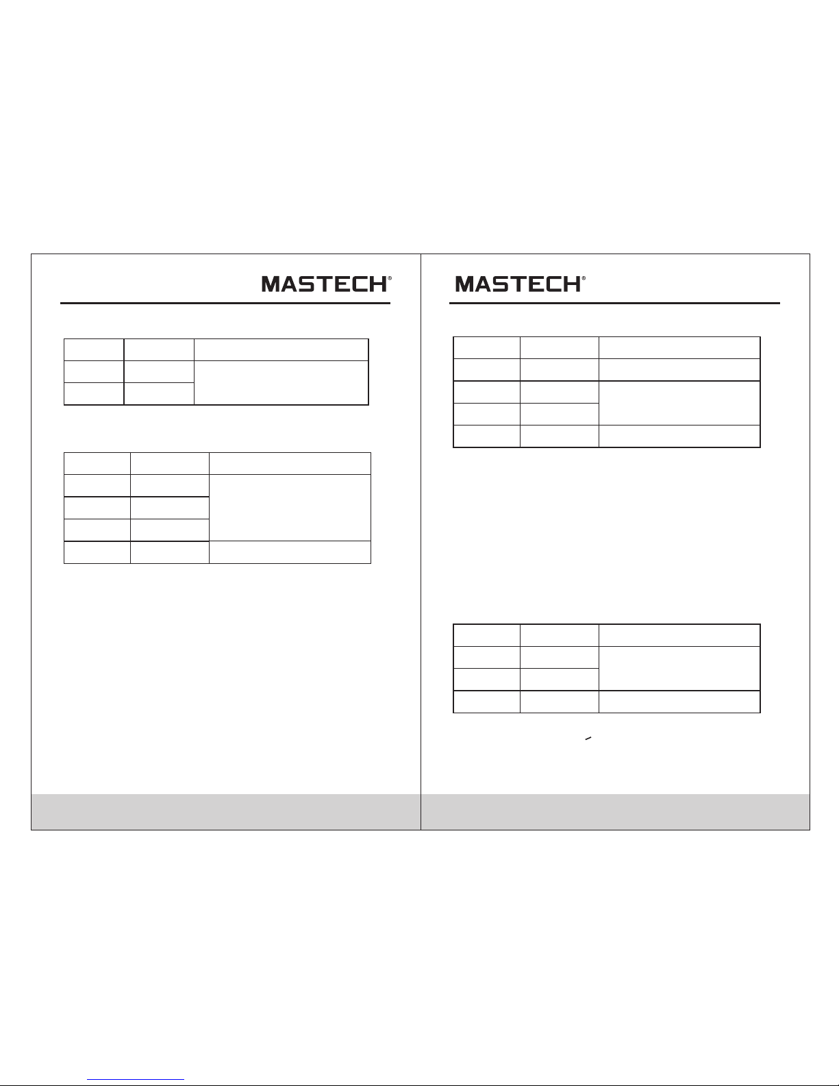
3.2.4 DC Curr ent
- Max. input cu rrent : 600A DC
±(3.0% of rdg + 10 digits)
Accuracy
Resolutio n
0.01A
0.1A
Range
66A
600A
3.2.5 DC Voltage
±(0.8% of rdg + 3digits)
Accuracy
Resolutio n
0.1mV
0.001V
Range
660mV
6.6V
0.01V
66V
- Input imped ance: 1 0MΩ
- Max. input vo ltage : 600V DC
±(1. 0% of rdg + 5digits)
0.1V
600V
Note:
At small volt age ran ge, uns teady r eadin gs will a ppear
before the te st lead s conta ct the ci rcuit . Th is is nor mal
because the m eter is h ighly s ensit ive. Wh en the te st
leads conta ct the ci rcuit , the tru e readi ng will b e shown .
3.2.6 AC Voltag e
±(1.2% of rdg + 5digits)
Accuracy
Resolutio n
0.1mV
0.001V
Range
660mV
6.6V
0.01V
66V
0.1V
600V
±(1.5% of rdg + 10digits)
±(1.5% of rdg + 10digits)
- Input imped ance: 1 0MΩ
- Max. input vo ltage : 600V Tru e RMS AC
- Frequency r ange: 4 0 to 400H z
- Response: t rue roo t mean sq uare va lue
Note:
At small volt age ran ge, uns teady r eadin gs will a ppear
before the te st lead s conta ct the ci rcuit . Th is is nor mal
because the m eter is h ighly s ensit ive. Wh en the te st
leads conta ct the ci rcuit , the tru e readi ng will b e shown .
3.2.7 Frequ ency
3.2.7.1 By A range ( from curre nt clam p):
±(1.5% of rdg + 5 d igits )
Accuracy
Resolutio n
0.1Hz
Range
660Hz
1kHz
0.0011Hz
0.0011Hz
>1kHz
Take it only as referance
- Measureme nt rang e: 10 ~ 1kH z
- Input curre nt rang e: >10A Tru e RMS AC (hi gher in put
current at hi gher fr equen cy)
- Max. Input cu rrent : 600A True R MS AC
Page 9

13 14
3.2.7.2 By V ra nge:
Accuracy
Resolutio n
0.1Hz
0.001kHz
Range
660Hz
6.6kHz
0.01kHz 10kHz
>10kHz
Take it only as referance
±(1.5% of rdg + 5 d igits )
- Measureme nt rang e: 10 ~ 10k Hz
- Input volta ge rang e:>0. 2V True RM S AC (high er inpu t
voltage at hi gher fr equen cy)
- Input imped ance: 1 0MΩ
- Max. input vo ltage : 600V Tru e RMS AC
3.2.8 Duty Cy cle
Accuracy
Resolutio n
0.1%
Range
10 - 95% ±3.0%
3.2.8.1 By A range ( from curre nt clam p):
- Frequency r espon se: 10 ~1 kHz
- Input curre nt rang e:>10 A True RMS AC (h igher i nput
current at hi gher fr equen cy)
- Max. input cu rrent : 600A
3.2.8.2 By V ra nge:
- Frequency r espon se: 10 ~ 10 k Hz
- Input volta ge rang e:>0. 2V True RM S AC (high er inpu t
voltage at hi gher fr equen cy)
- Input imped ance: 1 0MΩ
- Max. input vo ltage : 600V Tru e RMS AC
0.01kHz
Accuracy
Resolutio n
0.1Ω
0.001kΩ
Range
660Ω
6.6kΩ
0.01kΩ 66KΩ
0.1kΩ
660kΩ
±(1.2% of rdg + 2digits)
0.001MkΩ 6.6MΩ
0.1MΩ66MΩ
- Open circui t volta ge: 0.5 V
3.2.9 Resis tance
±(2.0% of rdg + 5digits)
3.2.10 Diod e
Function
Resolutio n
Range
displaying approximate
for ward volta ge of diode
0.001V
- Forward DC cu rrent ~1mA
- Reversed DC v oltag e~3.2 V
Resolutio n
Range
Built-in buzz er will so und,
if resistance is lower than
50±20Ω.
0.1Ω
- Open circui t volta ge~1V
3.2.11 Conti nuity
Function
Page 10

15 16
3.2.12 Capa citan ce
6.6µF
66µF
660µF
6.6mF
66mF
4. Operation Instruction
4.1 Holding Readings
4.1.1 Press t he “HOL D/B.L ” butto n to hold t he read ings
whil e takin g measu remen t and the v alue on t he
disp lay wil l be held .
4.1.2 Press t he “HOL D/B.L ” butto n again t o relea se the
read ing hol d funct ion.
4.2 Switching Ranges
4.2.1 When th e meter i s turne d on, it is a t the aut o range
mode f or meas uring c urren t, volt age, re sista nce,
capa citan ce and fr equen cy.
4.2.2 Press t he"RA N" butt on for ma nual ra nge mod e. The
rang e will go u p one lev el at eac h press a nd retu rn
to the l owest l evel wh en the hi ghest l evel is r eache d.
4.2.3 Press t he "RAN " butto n for one o r more se conds t o
retu rn to the a uto ran ge.
4.2.4 Press t he “RAN ” butto n to get ba ck to nor mal tes t
duri ng work ing in ma ximum o r minim um valu e
meas uring f uncti on,
Note:
At frequency range, meter can't be set to manual range mode.
4.3 Switching Frequency Or D uty
4.3.1 During working at the voltage or current ranges,
press the “Hz/%” button one time, frequency of the
voltage or current will be measured. Press the
“Hz/%” button twice, the meter will be changed into
the duty range for measuring the duty cycle of the
voltage or current. At the same time, the meter is
changed into manual mode.
4.3.2 Press the “Hz/%” button again, meter will be back
to the condition of the voltage or current measuring.
Note:
During working at ma ximum o r minim um valu e measu ring
function, t he mete r can't b e chang ed into f reque ncy or
duty cycle me asuri ng mode .
4.4 Switching Maximum Or Minimu m Valu e
4.4.1 At all ranges, press the "MAX/MIN" button one time,
the meter can be set to maximum value measuring
mode; press the button three times, the meter will
get back to normal test mode, and the maximum and
minimum value will be recorded by the chip.
4.4.2 Press the ”MAX/MIN” button more than one second
or press the“RAN” button, the meter will get back to
normal test.
For MS2128:
Accuracy
Resolutio n
0.001µF
Range
9.999µF
99.99µF
999.9µ F
0.001mF
9.999mF
0.01mF
99.99mF
0.01µF
0.1µF
For MS2108T:
Accuracy
Resolutio n
0.001µF
Range
0.001mF
±( 4.0% of rdg + 50digits)
±(4.0% of rdg + 3 d igits )
0.01mF
0.01µF
0.1µF
0.1nF
999.9nF
±( 4.0% of rdg + 5 digits)
0.01nF
99.99nF
0.001nF
9.999nF
±( 5.0% of rdg + 5 digits)
Page 11

- LED, which re quire s a large r worki ng curr ent, is t he
main source o f back li ght. Alt hough t he mete r is
equipped with a time r set at 60 s econd s (i.e. t he back
light will be o ff a utoma tical ly afte r 60 seco nds),
frequent us e of the ba ck ligh t will sh orten t he life o f
the batteri es. There fore, d o not use t he back l ight
unless nece ssary.
- When the batt ery vol tage is <3.7V, the sym bol “ ”
(battery lo w)wil l appea r on the LC D. When t he back
light is on, ev en if the b atter i s>3.7 V, the “ ” ma y
appear beca use of it s large w orkin g curre nt whic h
will cause th e volta ge to dro p. (The a ccura cy
of the m easur ement c annot b e assur ed when t he
“ “ symb ol appe ars.) I n this ca se, you n eed not
replace the b atter ies yet . Norma lly, the bat terie s
can last unti l the “ ” app ears wh en the ba ck ligh t
is not being us ed.
17 18
1) During mea surin g maxim um or min imum va lue, th e
mete r will be s et to man ual mod e autom atica lly.
2) During working at f reque ncy or du ty meas uring
func tion, t he mete r can't b e chang ed into m aximu m
or min imum va lue mea surin g mode.
Note:
4.5 Switching Functions
4.5.1 AC A range
4.5.1.1 Pre ss the “S EL” but ton, th e meter w ill get
into i nrush c urren t test mo de.
4.5.1.2 If pr ess the “ SEL” bu tton ag ain, th e meter
will g et into i nrush c urren t test mo de agai n.
4.5.1.3 Pre ss the “S EL” but ton mor e than on e secon d
or pre ss the “R AN”bu tton, t he mete r will ge t
back t o norma l test mo de.
4.5.2 DC A range
4.5.2.1 Pre ss the “S EL” but ton, th e meter w ill get
into z ero.
4.5.2.2 If pr ess the “ SEL” bu tton ag ain, th e meter
will g et into z ero aga in.
4.5.2.3 Pre ss the “S EL” but ton mor e than on e
seco nd or pre ss the “R AN” but ton, th e meter
will g et back t o the nor mal tes t mode.
4.5.4 Press t he ”SEL ” butto n to swit ch amon g
resi stanc e, diod e and con tinui ty rang es.
4.5.3 Press t he “SEL ” butto n to swit ch betw een AC
and DC m easur ement a t the vol tage ra nges.
4.6 Back Light And Clamp Lighting Bulb
4.6.1 Press t he “HOL D/B.L ” butto n for two o r more
seco nds to sw itch on t he back l ight if t he ligh t
in the e nviro nment i s too dim f or taki ng read ing,
whic h will la st for 60 s econd s.
4.6.2 Durin g the bac k light i s worki ng, pre ss the
“HOL D/B.L ” butto n for two o r more se conds , it
will b e turne d off.
4.6.3 At the cur rent ra nge, wh en the ba ck ligh t is
swit ched on , the cla mp ligh ting bu lb will b e turne d
on at th e same ti me.
Note:
4.7 Auto Power Off
4.7.1 If there is no any operation within any thirty minutes
after power is on, meter will auto power off.
4.7.2 After auto power off, if press the “SEL” button,
meter will recover the working condition.
4.7.3 Press both power on switch and one of ”MAX/MIN”
or “RAM”or “Hz/%”button at the same time more
than one second for exiting auto power off function.
Page 12

19 20
4.8 Preparating For Measur eme nt
4.8.1 Swit ch on the power by turni ng the ro tary selector.
If the batte ry voltage is lower tha n 3.7V, the “ ”
sym bol will appea r and the batteries sho uld be
rep laced .
4.8.2 The “ ” symbol sh ows th at the in put voltage or
cur rent should no t exceed the specified value in
ord er to pro tect the inter nal circuit fr om dam age.
4.8.3 Turn the rotar y selector to the requi red fu nctio n and
ran ge to be measured. Unde r the manual mo de,
cho ose the highes t range when the value scale to be
mea sured is unkno wn.
4.8.4 Conn ect the common test lea d first and the n the
cha rged test lead s when ma king connection. Take
awa y the cha rged test lead first wh en dis conne cting .
4.9 Measuring AC Current
WARNING
Beware of Ele ctroc ution . Ensur e that th e test le ads
are disconn ected f rom the m eter be fore ma king
current cla mp meas ureme nts.
4.9.1 Set the rotar y selector to the A range position.
4.9.2 Auto range mod e or manu al ran ge mode can be
sel ected by press ing the“RAN”button.
4.9.3 Pres s the tri gger to open ja w. Fully enclos e only on e
con ducto r.
4.9.4 Take the readin g on the LCD.
Note:
4) Under the manual range mode, when the scale of the
value to be measured is unknown beforehand, set the
range to the highest.
5) “ ” means the maximum input current is 600A rms AC.
1) Do not put mor e than one cab le into th e jaw duri ng test,
otherw ise incorrect test value might be obtained.
2) For optimum res ults, cen ter the co nduct or in the jaw.
3) At the manu al range mode, when onl y ‘O L’ is shown on
the LCD, it mea ns the mea surem ent has ex ceede d th e
range. A higher rang e should be se lecte d.
Correct
Incorrect
Page 13

21 22
4.10 Measuring Inrush Curr ent
WARNING
Beware of Ele ctroc ution .
Ensure that t he test l eads ar e disco nnect ed
from the mete r befor e makin g curre nt clam p
measurements.
4.10.1 Set the rota ry selector to the A rang e position.
4.10.2 Pre ss the tr igger to open jaw. Fully enclo se
onl y one con ducto r.
4.10.3 Pre ss the “S EL” to en ter the INRUSH curre nt
mea surem ent mode. Then LCD displa ys
“- - - -” until the motor sta rting up and be ing
det ected . The detec tion will be done only one
tim e and the output readin g will be hold.
4.10.4 Take the readi ng on the LCD.
Note:
1) Do not put mor e than one cab le into
the jaw dur ing test, otherwise inco rrect
test value might be obtained.
2) For optimum res ults, cen ter the co nduct or in the jaw.
3) At the manu al range mode, when onl y ‘O L’ is shown
on the LCD, it means the measurement has
exceed ed the ran ge. A higher range shou ld
be selected.
4) Under the manua l ra nge mode, when the scale of
the value to be measured is unknown beforehan d,
set the ran ge to the high est.
5) “ ” means the maximum in put current is
600A rms AC.
Correct
Incorrect
Page 14

23 24
4.11 Measuring DC Curren t
WARNING
Beware of Ele ctroc ution .
Ensure that t he test l eads ar e disco nnect ed
from the mete r befor e makin g curre nt clam p
measurements.
1) Do not put more than one cable into the jaw during
tes t, otherwise incorr ect test value might be
obt ained .
2) Fo r optimum resu lts, press the “SEL” bu tton to
mak e the met er get in to zer o first.
3) Fo r optimum resu lts, center th e conductor in the jaw.
4) At the manua l range mode, when only 'O L' or '-O L'
is shown on the LCD, it means the measurement
has exceeded the range. A higher range sh ould
be selected.
5) Un der the manual range mo de, wh en the sc ale
of the value to be mea sured is unkno wn beforehand,
set the rang e to the highes t.
6) “ ”means th e maximum inpu t curr ent is 60 0A DC.
4.11.1 Set the ro tary selector to the A range position.
4.11.2 Auto range mod e or manual ran ge mode can be
sel ected by press ing the “RAN” button.
4.11.3 Press the “SEL” button, the meter will be set
to zero.
4.11.4 Press the trigg er to ope n jaw. Fully enc lose only
one conductor.
4.11.5 Tak e the rea ding on the LCD .
4.11.6 Symbol “-” will be displ ayed on LCD if the
dir ectio n of the current is negative.
Note:
Page 15

WARNING
Beware of Ele ctroc ution .
Pay special a ttent ion to av oid ele ctric s hock
when measur ing hig h volta ge.
Do not i nput th e volta ge whic h more th an
600V rms AC.
4.12 Measuring AC Voltage
4.12.1 Plug t he blac k test le ad into t he COM ja ck and
the re d test le ad into t he INPU T jack.
4.12.2 Set th e rotar y selec tor to V po sitio n to make
the me ter get i nto AC V ran ge.
4.12.3 Auto ra nge mod e or manu al rang e mode ca n
be sel ected b y press ing the “ RAN” bu tton.
4.12.4 Conn ect the t est lea ds to the v oltag e sourc e or
load t ermin als for m easur ement .
4.12.5 Take the reading on the LCD.
Note:
1) At small vol tage range, un stead y read ings may
app ear before the test lea ds con tact the circu it.
This is normal because the me ter is hi ghly sensitive.
Whe n the tes t leads contac t the cir cuit, the true
rea ding will be shown.
2) At the manua l range mode, when only 'OL' is shown
on the LCD, it means the measurement has exceeded
the range. A highe r range should be selec ted.
3) At the manua l range mode, when the scale of the
val ue to be measured is unk nown beforehand, se lect
the highest range first an d lowe r the ran ge gradually.
4) “ ” means the maximum in put voltage is 600V rms AC.
5) If the test result is more than 610 V rms AC , symb ol
“OL ” will be displayed on LCD and th e build-up
buz zer will sound .
25 26
4.13 Measuring DC Voltage
WARNING
Beware of Ele ctroc ution . Pay spe cial at tenti on to
avoid elect ric sho ck when m easur ing hig h volta ge.
Do not input th e volta ge whic h more th an 600V D C.
4.13.1 Plug t he blac k test le ad into t he COM ja ck and
the re d test le ad into t he INPU T jack.
4.13.2 Set th e rotar y selec tor to at t he V rang e posit ion.
4.13.3 Pres s the“S EL” but ton to tu rn to DC V ra nge.
Auto ra nge mod e or manu al rang e mode ca n be
sele cted by p ressi ng the “R AN” but ton.
4.13.4 Conn ect the t est lea ds to the v oltag e sourc e or
load t ermin als for m easur ement .
4.13.5 Take the reading on the LCD. The pola rity
symb ol deno tes the p olari ty of the e nd
conn ected b y the red t est lea d.
Note:
1) At small volt age ran ge, uns teady r eadin gs will
appear befo re the te st lead s conta ct the ci rcuit .
This is no rmal be cause t he mete r is high ly sens itive .
When t he test l eads co ntact t he circ uit, th e true
reading wil l be show n.
2) Under the ma nual ra nge mod e, when o nly
‘O L ’ o r ‘- O L’ is sho wn on the L CD, it me ans the
measureme nt has ex ceede d the ran ge. A highe r
range shoul d be sele cted.
3) Under the ma nual ra nge mod e, when t he scal e
of the v alue to b e measu red is un known b efore hand,
select the hi ghest r ange fi rst and l ower th e
range gradu ally.
Page 16

27 28
4) “ ” mea ns the ma ximum i nput vo ltage i s 600V DC .
5) If th e test re sult is m ore tha n 610V DC , symbo l “O L”
will be displ ayed on L CD and th e build -up buz zer
will sound.
9V
Page 17

29 30
4.14 Measuring Frequency
4.14.1 By A range (f rom cur rent cl amp):
WARNING
Beware of Ele ctroc ution .
Ensure that t he test l eads ar e disco nnect ed
from the mete r befor e makin g curre nt clam p
measurements.
4.14.1.1 Set the ro tary selector to the A range
(A~ or A ) posi tion.
4.14.1.2 Press the trigg er to ope n jaw. Fully enc lose
onl y one con ducto r.
4.14.1.3 Press the “Hz/% ” to swit ch to the frequ ency
measurement.
4.14.1.4 Tak e the rea ding on the LCD .
Note:
1) Do not put more than one cable into the jaw during
tes t, other wise incorr ect test value might be obtained.
2) Fr equen cy test range is 10Hz - 1kHz.‘00.0’ will be
dis playe d on LCD if the test freque ncy is lower th an
10. 0 Hz. It is possib le to tes t the frequenc y whic h is
hig her than 1 kHz but the tolerance of the test result
can not be ensure.
3) “ ” means the maximum inp ut current is
600 A rms AC.
Page 18

31 32
4.14.2 By V ran ge:
WARNING
Beware of Ele ctroc ution .
Pay special a ttent ion to av oid ele ctric s hock
when measur ing hig h volta ge.
Do not i nput th e volta ge whic h more th an
600V rms AC.
4.14.2.1 Plug the black test lead into the COM jack
and the red test lead into the INPUT jack.
4.14.2.2 Set the ro tary selector to the V range
pos ition .
4.14.2.3 Press the "Hz/% " to swit ch to fre quenc y
mea surem ent.
4.14.2.4 Connec t test le ads to th e two end s of the
sou rce or lo ad for me asure ment.
4.14.2.5 Tak e the rea ding on the LCD .
Note:
1) Fr equen cy test range is 10Hz -1 0kHz. '0 0.0' will be
dis playe d on LCD if the tes t frequency is lower th an
10. 0 Hz. It is possib le to test the frequency whic h is
hig her than 10kHz but the tolera nce of th e test re sult
can not be ensure.
2) “ ” means the maximum in put voltage is
600 V rms AC .
Correct
Incorrect
Page 19

33 34
4.15 Measuring Duty
4.15.1 By A range ( fr om curr ent cla mp):
WARNING
Beware of Ele ctroc ution .
Ensure that t he test l eads ar e disco nnect ed
from the mete r befor e makin g curre nt clam p
measurements.
4.15.1.1 Set the ro tary selector to the A range
( A or A ) po sitio n.
4.15.1.2 Press the trigg er to ope n jaw. Ful ly enc lose
onl y one con ducto r.
4.15.1.3 Press the "Hz/% " to swit ch to the DUTY
mea surem ent.
4.15.1.4 Tak e the rea ding on the LCD .
Note:
1) Do not put more than one cable into the jaw during
tes t, otherwise incorr ect test value might be obtai ned.
2) If the duty cycle is less than 10%, symbol 'UL' will be
dis playe d on LCD; if the du ty cycle is more than
94. 9%, symbol 'O L' will be displayed on LCD.
3) The input sig nal frequency range is 10 – 1kHz. It is
pos sible to test duty cycl e of the higher than 1 kHz
fre quenc y signal, but the toler ance of the tes t result
can not be ensure.
4) “ ” means the maximum in put current is
600 A rms AC.
Page 20

35 36
4.15.2 By V ran ge:
WARNING
Beware of Ele ctroc ution .
Pay special a ttent ion to av oid ele ctric s hock
when measur ing hig h volta ge.
Do not i nput th e volta ge whic h more th an
600V rms AC.
4.15.2.1 Plug the black test lead into the COM jack and
the red test lead int o the INP UT jac k.
4.15.2.2 Set the ro tary selector to the V range position .
4.15.2.3 Press the "Hz/% " to swit ch to DUT Y
mea surem ent.
4.15.2.4 Connec t test le ads to th e two end of the so urce
or load for measurement.
4.15.2.5 Tak e the rea ding on the LCD .
Note:
1) If the duty cycle is less than 10%, symbol 'UL' will be
dis playe d on LCD; if the du ty cycle is more than
94. 9%, symbol 'O L' will be displayed on LCD.
3) The input sig nal frequency range is 10 – 10 kHz. It is
pos sible to test duty cycl e of the higher than 10 kHz
fre quenc y signal, but the toler ance of the tes t result
can not be ensure.
3) “ ” means the maximum in put voltage is
600 V rms AC .
Page 21

37 38
4.16 Measuring Resist anc e
WARNING
Beware of Ele ctroc ution .
When measur ing in- circu it resi stanc e, make
sure that the p ower of t he circ uit und er test
has been turn ed off an d that al l capac itors
have been ful ly disc harge d.
4.16.1 Plu g the bla ck test lead in to the CO M jack an d
the red test lead int o the INP UT jac k.
4.16.2 Set the rota ry selector to the Ω range
pos ition to make the meter get into Ω rang e.
4.16.3 Au to range mode or manual range mode can be
sel ected by press ing the “RAN” button.
4.16.4 Con nect the test leads to the ends of the res istor
or circuit for measurement.
4.16.5 Take the readi ng on the LCD.
Note:
1) At the manua l range mode, when only 'O L' is shown
on the LCD, it means the measurement has exceeded
the range. A highe r range should be selec ted.
2) Wh en the in put is op en, 'O L' will appear on the LCD
to indicate that the range has been excee ded.
3) Fo r measuring re sista nce above 1MΩ, it may ta ke
a few seco nds to get a steady read ing. This is norm al
for high res istan ce reading.
Page 22

39 40
4.17 Testing Diode
4.17.1 Plu g the bla ck test lead in to the CO M jack an d
the red test lead int o the INP UT jac k.
4.17.2 Set the rota ry selector to the Ω range
pos ition .
4.17.3 Pre ss the "S E L" butt on to swi tch to te st.
4.17.4 Con nect the red test lead to the ano de and th e
bla ck test lead to th e cathode of th e diode for
tes ting.
4.17.5 Take the readi ng on the LCD.
Note:
1) The meter wil l show th e appr oxima te forward vol tage
dro p of the diode.
2) Wh en the te st leads have been reversed or open,
'O L' will appear on the LCD.
Page 23

42
4.18 Testing Continuity
WARNING
Beware of Ele ctroc ution .
Make sure tha t the pow er of the c ircui t has
been turned o ff and th e capac itors h ave bee n
fully disch arged b efore t estin g the
continuit y of a circ uit.
4.18.1 Plu g the bla ck test lead in to the CO M jack an d
the red test lead int o the INP UT jac k.
4.18.2 Set the rota ry selector to the Ω range
pos ition .
4.18.3 Pre ss the "S E L" butt on to swi tch to co ntinu ity
tes t.
4.18.4 Con nect the test leads to the two en ds of the
cir cuit for measu remen t.
4.18.5 If the resis tance of the circuit be ing te sted is less
tha n 50±20Ω, the built-in buzze r will so und.
4.18.6 Take the readi ng on the LCD.
Note:
If th e test le ads are open or the resi stanc e of the circuit
is ov er 660Ω (for MS2128) or 600Ω (for MS21 08T) , “O L”
will appea r on the LCD.
41
Page 24

44
4.19 Measuring Capaci tan ce
WARNING
Beware of Ele ctroc ution .
To avoid el ectri c shock , make su re that t he
capacitor s have be en full y disch arged
before meas uring t he capa citan ce of a
capacitor.
4.19.1 Plu g the bla ck test lead in to the CO M jack an d
the red test lead int o the INP UT jac k.
4.19.2 Set the rota ry selector to the rang e posi tion.
4.19.3 Af ter fully disc harge d the cap acito r, conn ect the
tes t leads to the two ends of the capacitor for
mea surem ent.
4.19.4 Take the readi ng on the LCD.
Note:
It ma y take so me time (about 10 seconds for the
66mF range ) for ste ady readings when me asuring
high capac ity.
43
Page 25

46
5. Maintenance
45
5.1 Replacing The Batterie s
WARNING
To avoid el ectri c shock , make su re that t he test
leads have be en clea rly mov e away fr om the
circuit und er meas ureme nt befo re open ing the
battery cov er of the m eter.
5.1.1 If the sign “ ” appea rs, it me ans that the
bat terie s should be replaced.
5.1.2 Loos en the fi xing screw of the batte ry cov er and
rem ove it.
5.1.3 Repl ace the exhaus ted batteries with new ones.
5.1.4 Put the batte ry cover back and fix it again to its
ori gin form.
Note:
Do no t reverse the polarity of the batteri es.
WARNING
Do not m ix old and new b atter ies. Do n ot mix
alkaline, standard (c arbon -zinc ), or r echargeable
(ni-cad , ni-mh, etc ) batte ries.
5.2 Replacing Test Leads
6. Accessories
Replace test leads i f leads b ecome d amage d or worn .
Use meet EN 61010-031 standard, rated CAT III 600V, or
better test leads.
WARNING
To avoid electric shock,make sure the probes are
disconnected from the measured circuit before removingthe
rear cover. Make sure the rear cover is tightly screwed before
using the instrument.
WARNING
Test Leads
1 pair
Operating Manual
1 piesce
1.5V AAA Battery
3 pieces
1)
2)
3)
Case
1 piece
4)
Page 26

R-00-05-1584
 Loading...