

Page 1
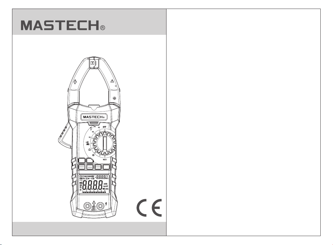
MS2115B
DUAL DISPLAY DIGITAL CLAMP METER
OPERATION MANUAL
1000 V
CAT III
6000 Counts
T - Rms
Inrush
V
INRUSH
FUNC
REL
MAX
ZERO
MIN
MS2115B
COM INPUT
Hz
A
600/1000
A
60
Hz
B.L.
HOLD
RANGE
AC/DC CLAMP METER
MAX
1000A
Page 2

CONTENTS CONTENTS
1. Safety Information
1.1 Preparation
1.2 Usage
1.3 Mark
1.4 Maintenance
2. Description
2.1 Part Name
2.2 Switch and Button Description
2.3 LCD Display
..................................................1
..........................................................2
.............................................................3
...............................................4
...........................................4
...................................................5
................................................7
3. Specification
3.1 General
3.2 Technique Data
........................................................9
4. Operating Guidance
4.1 Reading Hold
4.2 Measuring Range Switch
4.3 Back Light and Clamp Head Light
4.4 Maximum/Minimum
Measurement Choice
4.5 Function Choice
.............................................16
................................1
.....................7
........................................9
..........................................10
...........................16
............................16
............................17
........................................17
...............16
4.6 Relative Measurement
4.7 Surge Measurement
4.8 Automatic Power-Off
4.9 Measurement Preparation
4.10 Current Measurement
4.11 Voltage Measurement
4.12 Frequency And Duty
Ratio Measurement
4.13 Resistance Measurement
4.14 Diode Test
4.15 Circuit Continuity Test
4.16 Capacitance Measurement
4.17 Surge Current Measurement
4.18 Non-Contact Voltage Detection
4.19 USB Communication
5. Maintenance
5.1 Replace Battery
5.2 Replace Probe
6. Attachments
.............................17
.................................18
.................................18
........................18
.............................19
.............................20
..............................20
.......................21
..............................................21
.............................22
.....................22
...................22
...............23
...............................24
......................................24
.........................................24
..........................................25
.......................................25
Page 3

1. Safety Information
War ning
Plea se part icula rly not e th at inap propr iate us e may
caus e shock o r damag e to the me te r when us ing.
When u sing th e meter, c omply w it h commo n safet y
proc edure s and com plete ly f ollow t he safe ty meas ures
stat ed in the o perat ion man ua l.
In ord er to mak e full us e of the me te r's fun ction s and
ensu re safe o perat ion, pl ea se care fully r ead and
foll ow the pr ocedu res in th e op erati on manu al.
This m eter me ets to UL /CAS6 10 10-1 wi th meas ureme nt
cate gory (C AT lV 600 V and CAT III 1000 V.) and pol lutio n
degr eease f ollow t he safe ty g uidel ines to e nsure s afe
usag e of the me ter.
Prot ectio n provi ded by th e in strum ent wil l be impa ired
if use d in a mann er not sp ecifi ed b y the man ufact urer.
The me ter wil l provi de sati sf actor y servi ces to yo u if
you us e and pro tect it a pprop ri ately.
1.1 Preparation
1.1. 1 When us ing the m eter, th e us er shou ld comp ly
with s tanda rd safe ty r ule s fo r:
- Gene ral sho ck prot ec tio n
- Prop er use of t he mete r
1.1. 2 Pleas e check f or dama ge c aused d uring
tran sport ation a ft er rece iving t he mete r.
1.1. 3 If the me ter is st or ed an d sh ipped u nder ha rd
cond ition s, plea se c onf ir m that th e meter
oper ates pr operl y or i s dam ag ed.
1.1. 4 Probe s hould b e in good c on ditio n. Befo re use,
plea se chec k wheth er t he pr ob e insul ation i s
dama ged and w hethe r th e met al w ire is ba re.
1.1. 5 Use the p robe ta ble pro vi ded wit h the met er to
ensu re safe ty. If neces sa ry, replac ed the pr obe
with a nothe r ident ic al pr ob e or one wi th the sa me
spec ifica tion.
1.2 Usage
1.2. 1 When us ing the m eter, se le ct the ri ght fun ction
and me asuri ng rang e.
1.2. 2 Don't m ake mea surem en ts that e xceed i ndica ted
valu es in eac h measu ri ng ra ng e.
1.2. 3 When me asuri ng circ ui ts with t he mete r
conn ected , do not co nt act wit h probe t ip
(met al part ).
1.2. 4 If volt age to be m easur ed i s more th an 60V DC o r
30V AC (R MS), al ways ke ep y our f in gers be hind
fing er prot ectio n de vic e.
1.2. 5 Do not me asure v oltag e gr eater t han AC 750 V.
1.2. 6 When se lecti ng the ma nu al meas uring r ange, i f
you do n't kno w the val ue t o be me as ured, c hoose
the hi ghest m easur in g ran ge a nd decr ease
grad ually u ntil th e co rre ct r ange is d ispla yed.
1.2. 7 Befor e rotat ing sel ec tion sw itch to c hange
meas uring f uncti on , rem ov e probe f rom the
circ uit to be m easur ed .
1.2. 8 Don't m easur e resis to rs, cap acito rs, dio des and
circ uit con necti on s wit h po wer.
1.2. 9 Durin g tests o f curre nt , resis tors, c apaci tors,
diod es and ci rcuit c on nec ti ons, av oid con necti ng
the me ter to vo ltage s ou rce .
1.2. 10 Do not m easur e capac it ance be fore ca pacit or is
disc harge d compl et ely.
01 02
Page 4

1.2. 11 Do n ot use th e meter i n ex plo si ve gas, v apor or
dust y envir onmen t.
1.2. 12 If you f ind any a bnorm al p henom ena or fa ilure
on the m eter, st op usin g th e meter i mmedi ately.
1.2. 13 Do not u se the me ter unl es s the met er bott om
case a nd the ba ttery c ov er are co mplet ely
fast ened in o rigin al p lac es .
1.2. 14 Don' t store o r use the m et er in dir ect sun light ,
high t emper ature a nd h igh h um idity.
1.3 Mark
Note ( Impor tant sa fe ty info rmati on. Ref er to
the op erati on manu al )
Dang erous e lectr ic cond uc tor.
Doub le insu latio n pr otect ion (cl ass II)
CAT III Acco rding t o pulse v ol tage to leran ce
prot ectio n level p ro vided b y IEC 610 10-1
stan dard ov ervol ta ge (ins talla tion) l evel II I and
poll ution d egree 2 .
The mete r compl ies wit h EU s tanda rd
Grou nding
This p roduc t has bee n teste d to t he requ ireme nts
of CAN /CSA- C22.2 N o. 6101 0- 1, seco nd edit ion,
incl uding Am endme nt 1, or a la te r versi on of the
same s tanda rd inco rpora ti ng the sa me leve l of
test ing req uirem ents” .
C
CONF ORMS TO UL STD . 61010 -1 , IEC
6101 0-2-0 32 CERTIF IED TO C SA ST D.
C22. 2 No. 610 10-1 an d 61010 -2 -03 2
1.4 Maintenance
1.4. 1 Don't t ry to ope n the met er b ottom c ase to ad just
or rep air. Suc h opera ti ons o nl y can be ma de by
tech nicia ns who fu ll y und er stand t he mete r and
elec trica l shock h az ard .
1.4. 2 Befor e openi ng the me te r botto m case or b atter y
cove r, remov e probe f ro m the c ir cuit to b e measu red.
1.4. 3 To avo id inco rrect r eadin gs a nd poss ible el ectri c
shoc k, when " " a ppear s on t he mete r displ ay,
repl ace the b atter y im med ia tely.
1.4. 4 Clean t he mete r with da mp c loth an d mild
dete rgent . Do not us e ab ras iv es or sol vents .
1.4. 5 Turn pow er off when t he mete r is n ot used , and
swit ch the me asuri ng r ang e to O FF posi tion.
1.4. 6 If the me ter is no t us ed fo r lo ng time , remov e the
batt ery to pr event d am age to th e meter.
2. Description
- The mete r is a port able, p ro fes si onal me asuri ng
inst rumen t with LC D displ ay a nd back l ight fo r easy
read ing by us ers. Me asuri ng r ange sw itch is o perat ed
by sin gle han d for eas y opera ti on. The met er has
over load pr otect ion and a l ow b atter y indic ator. It i s
an ide al mult ifunc tion me te r for pro fessi onals ,
fact ories , schoo ls, fan s an d famil y use.
- The mete r is used f or meas ur ing AC c ur rent, D C
curr ent, vo ltage , DC volt ag e, freq uency, dut y ratio ,
resi stanc e, capa citan ce m easur ement a nd circ uit
conn ectio n, diod e test an d no n-con tact vo ltage
dete ction .
- The mete r has aut omati c me asu ri ng rang e and
manu al meas uring r ange.
- The mete r has rea ding ho ld func ti on.
03 04
Page 5
- The mete r has max . measu ri ng fu nc tion.
- The mete r has min . measu ri ng fu nc tion.
- The mete r has cla mp head f re que nc y
meas ureme nt func tion.
- The mete r has aut o power -off f unc ti on.
- The mete r has rel ative m easur in g funct ion.
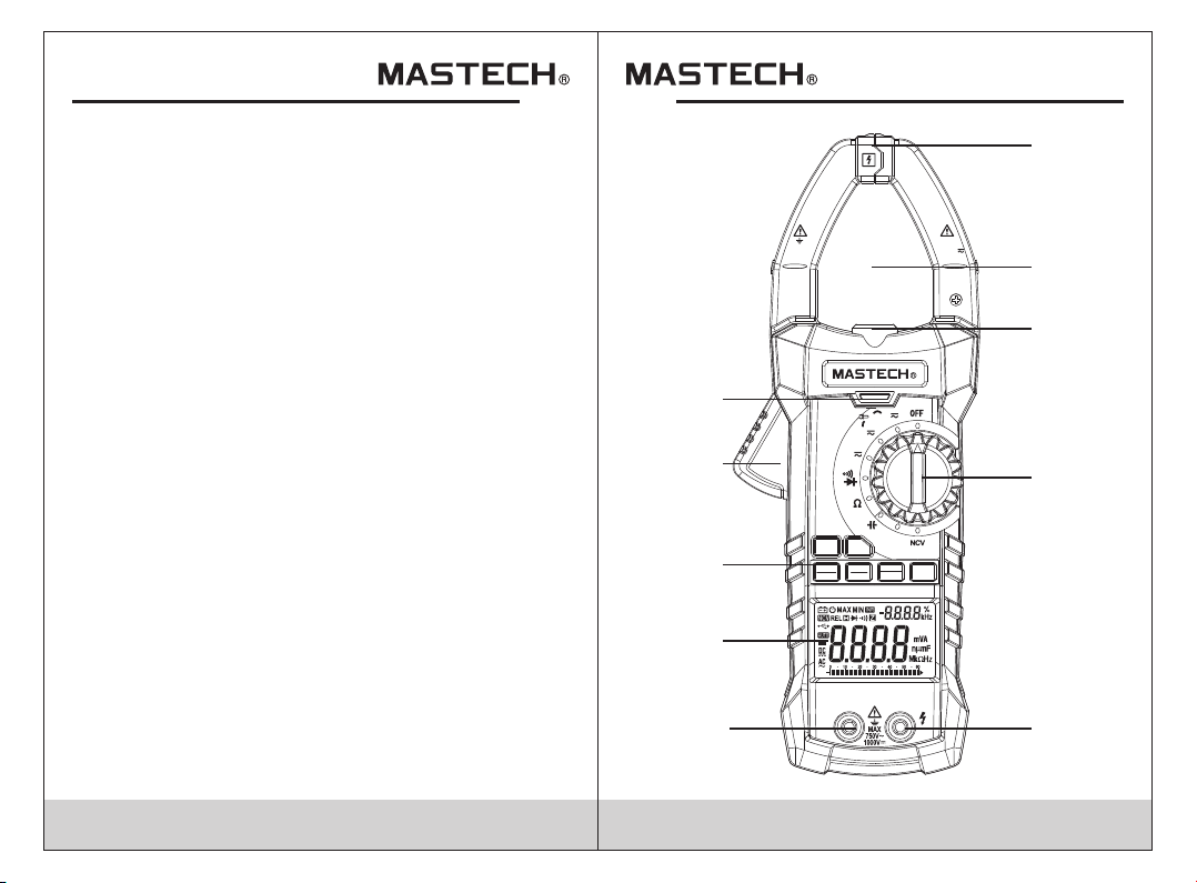
2.1 Part Name
(1) No n-con tact vo ltage d et ectio n sensi ng area
(2) Cu rrent c lamp he ad: use d fo r curre nt meas ureme nt.
(3) Cl amp hea d light
(4) Ro tary sw itch
(5) In put Soc ket
(6) NC V indic ator
(7) Tri gger
(8) Ke y
(9) Di splay
(10) U SB comm unica tion so ck et
1
1000 V
CAT III
MAX
1000A
2
3
6
7
6000 Counts
T - Rms
Inrush
Hz
A
600/1000
A
60
V
4
INRUSH
8
REL
ZERO
MS2115B
FUNC
MAX
MIN
AC/DC CLAMP METER
9
COM INPUT
10
05 06
RANGE
Hz
B.L.
HOLD
5
Page 6

2.2 Rotary Switch, Button And I npu t Jac k
Description
B.L/ RANGE b utton : used fo r me asuri ng rang e switc h
or bac k light c ontro l.
FUNC b utton : used fo r measu ri ng func tion sw itch.
HOLD b utton : data ho ld.
REL/ ZERO bu tton: U se d for e nt ering r elati ve
meas ureme nt stat e (when m ak ing non -DC cur rent
meas ureme nt), DC c urren t ze roing f uncti on
(DC cu rrent m easur ement ).
INRU SH butt on: Sur ge curr en t measu remen t.
MAX/ MIN but ton: us ed for ma xi mum/m inimu m
meas ureme nt func tion sw it ch.
Rota ry swit ch: use d for shu tt ing off pow er or
func tion se lecti on.
INPU T jack: v oltag e, resi st ance, f reque ncy, duty
rati o, capa citan ce, dio de , circu it conn ectio n input
wire c onnec ting te rmina l.
COM ja ck: vol tage, r esist an ce, fre quenc y, du ty rati o,
capa citan ce, dio de, cir cu it conn ectio n commo n wire
conn ectin g termi nal.
2.3 LCD Display
AC, DC
AUTO
MAX /MIN
INR
REL
Z
H
%
mV,V,A
nF,μF,mF
Ω,kΩ,MΩ
Hz,kHz,MHz
NCV
Alte rnati ng Curr ent, di re ct curr ent
Diod e, on/o ff
Auto matic m easur ing ran ge m ode
Maxi mum/m inimu m measu re ment
Surg e curre nt test
Rela tive me asure ment mo de
Auto matic p ower- off indic at or
DC cur rent ze roing f uncti on
LOW BATTERY
Read ing hol d state
Perc entag e (duty r atio)
Mill ivolt , Volt (vo ltage ), Am pere (c urren t)
Nano f arad, M icrof arad, M il lifar ad
Ohm, K ilohm , Megoh m (resi st ance)
Hert z, Kilo hertz , Megah er tz (fre quenc y)
Non- conta ct volt age det ec tion
USB co mmuni catio n indic at or
07 08
Page 7

3. Specificatio ns
Each y ear, at a mi nimum , the met er s hould b e
reca libra ted whe n tempe ra ture is 1 8°C ~ 28° C and
rela tive hu midit y is less t ha n 75%.
3.1 General
• Auto matic m easur ing ran ge a nd manu al
meas uring r ange.
•
Full m easur ing ran ge over lo ad prot ectio n.
•
The ma ximum a llowa ble vol ta ge betw een
meas ureme nt end an d groun d: 1 000V DC o r 750V AC
•
Oper ation al heig ht: max im um 2000 m
•
Disp lay: LC D
•
Disp layed m aximu m value : 60 00 digi t.
•
Pola rity in dicat ion: au to matic i ndica tion, ' -' mean s
nega tive po larit y.
•
Exce eding m easur ing ran ge d isp la y: '0L' o r '-0L' .
•
Samp ling ra te: abo ut 4 time s/ sec.
•
Unit d ispla y: has fu nctio n an d power u nit dis play.
•
Auto o ff t ime: 15 m in
•
Powe r suppl y: DC pow er 9V
•
Batt ery typ e: NEDA 16 04, 6F2 2
•
Batt ery low v oltag e indic at ion: LC D displ ays
symb ol.
•
Temper ature c oeffici ent: le ss t han 0.1 ×accu racy/ °C
•
Oper ation al temp eratu re : 18°C ~ 28 °C
•
Stor age tem perat ure: -1 0° C ~ 50°C
•
Dime nsion : 238×9 2×50m m
•
Weight : about 4 20g (in cludi ng b atter y)
3.2 Tec hni cal I ndi cat ors
3.2. 1 True RMS Z ero Inp ut C har ac teris tic
3.2. 1.1 For m easur ing non -s inuso idal wa ve sign als,
use th e true RM S measu ri ng meth od, whi ch
has le ss erro r than th e tr aditi onal av erage
resp onse me asuri ng m eth od .
3.2. 1.2 The tru e RMS met er c an ac cu ratel y measu re
non- sinus oidal w av e sig na ls, but i n AC funct ion,
when t here is n o signa l to b e mea su red (in put
term inal sh ort cir cu it in AC vol tage gr ade), t he
clam p meter m ay show a r ea din g fr om 1 to 50.
These de viati ng read in gs ar e no rmal. I n the
desi gnate d measu re men t ra nge, th ey will n ot
affect t he mete r's acc ur acy.
3.2. 1.3 True R MS can be m easur ed o nly whe n input
sign al reac hes a cer ta in le ve l. Theref ore,
meas uring r ange of AC v ol tag e an d curre nt
shou ld be spe cifie d at 2 %~1 00 % of full r ange.
3.2. 2 AC Cur rent
Measuring range
60A
600A
1000 A
- Maxi mum inp ut curr ent: 10 00 A AC
- Freq uency r ange: 5 0 ~ 60Hz;
Resolution
0.01 A
0.1A
1A
Accuracy
±(2. 5% read ing + 8 dig its)
09 1 0
Page 8

3.2. 3 DC Curr ent
Measuring range
60A
600A
1000 A
Resolution
0.01 A
0.1A
1A
Accuracy
±(2. 5% read ing + 8 dig its)
- Maxi mum inp ut curr ent: 10 00 A DC
3.2. 4 Surge C urren t
Measuring range
60A
600A
1000 A
Resolution
0.01 A
0.1A
1A
Accuracy
< 60A for r efere nce onl y
±(10 % readi ng + 60 dig its)
Time of i ntegr ation : 100ms ; me asure ment ra nge:
10~1 000A; f reque ncy ran ge : 40~40 0Hz
3.2. 5 DC Voltage
Measuring range
Resolution
Accuracy
0.1m V600m V
6V
60V
600V
1000 V
0.00 1V
0.01 V
0.1V
1V
±(0. 5% read ing + 5 dig its)
±(0. 8% read ing + 4 dig its)
- Inpu t imped ance: 1 0MΩ
- Maxi mum inp ut volt age: 75 0V AC ( RMS) or 1 000V DC
- 600m V measu ring ra nge can b e in putte d only by
RANG E key.
Note:
In the s mall vo ltage m easur in g range , the pro be is not
conn ected w ith the c ircui t to b e teste d, and th e meter
may ha ve fluc tuati ng read in gs, Thi s is norm al and
caus ed by the m eter' s high se ns itivi ty, and does n ot
affect a ctual m easur ement r es ults.
3.2. 6 AC Voltag e
Measuring range
Resolution
Accuracy
0.1m V600m V
6V
60V
600V
750V
0.00 1V
0.01 V
0.1V
1V
±(0. 8% read ing + 5 dig its)
±(0. 8% read ing + 4 dig its)
- Inpu t imped ance: 1 0MΩ
- Maxi mum inp ut volt age: 75 0V AC ( RMS) or 1 000V DC
- Freq uency r ange: 5 0 ~ 60Hz
- 600m V measu ring ra nge can b e in putte d only by
RANG E key.
Note:
In the s mall vo ltage m easur in g range , the pro be is not
conn ected w ith the c ircui t to b e teste d, and th e meter
may ha ve fluc tuati ng read in gs, This is n ormal a nd
caus ed by the m eter' s high se ns itivi ty. Thi s does no t
affect t he actu al meas ur eme nt r esult s.
11 12
Page 9

3.2. 7 Frequ ency
3.2. 7.1 Cla mp head m easur in g frequ ency (t hroug h
grad e A):
Measuring range
60.0 0Hz
Resolution
0.01 Hz
600. 0Hz 0.1H z
6.00 0kHz
1Hz
Accuracy
±(1. 5% read ing + 5 dig its)
- Meas uring s cope: 1 0Hz~1 kH z
- The inpu t signa l range :> 20A AC (RM S) (inp ut
curr ent wil l incre ase whe n th e frequ ency to b e
meas ured in creas es)
3.2. 7.2 Throu gh grad e V:
Measuring range
Resolution
Accuracy
0.01 Hz60.0 0Hz
600. 0Hz
6.00 0kHz
0.1H z
1Hz
±(1. 5% read ing + 5 dig its)
10Hz60. 00kHz
- Meas uring s cope: 1 0Hz~1 0k Hz
- The inpu t volta ge rang e: > 20mV AC ( RM S) (inp ut
volt age wil l incre ase whe n th e frequ ency to b e
meas ured in creas es)
3.2. 7.3 Throu gh Hz gra de:
Measuring range
Resolution
Accuracy
0.01 Hz60.00 Hz
600. 0Hz
6.00 0kHz
60.0 0kHz
600. 0kHZ
6.00 0MHZ
0.1H z
1Hz
0.01 kHz
0.1k HZ
1kHZ
±(0. 3% read ing + 5 dig its)
0.01MHZ60.00MHZ
- The input sign al: VPP 3V square wave ; Overload
pro tection: 250V DC or AC (RMS )
3.2. 8 Duty Ra tio
Measuring range
Resolution
Accuracy
10-9 0% ±3.0 % 0.1%
3.2. 9 Resis tance
Measuring range
600Ω
6kΩ
60kΩ
600k Ω
6MΩ
60MΩ
Resolution
0.1Ω
0.00 1kΩ
0.01 kΩ
0.1k Ω
0.00 1MΩ
0.1M Ω
Accuracy
±(0.8% reading + 3 digits)
±(1.2% reading + 3 digits)
- Over load pr otect ion: 25 0V D C or AC (RMS )
13 14
Page 10

3.2. 10 Circ uit Con ti nui ty Test
Measuring range
FunctionResolution
If the r esist ance of c ircui t to
0.1Ω
be mea sured i s less th an
50Ω, t he mete r's bui lt-in
buzz er may so und.
- Over load pr otect ion: 25 0V D C or AC (RMS )
3.2. 11 Capac itanc e
Measuring range
6.00 0nF
60.0 0nF
600. 0nF
6.00 0µF
60.0 0µF
600. 0µF
6.00 0mF
60.0 0mF
Resolution
0.00 1nF
0.01 nF
0.1n F
0.00 1µF
0.01 µF
0.1µ F
0.00 1mF
0.01 mF
Accuracy
±(3. 0% read ing + 5 dig its)
- Over load pr otect ion: 25 0V D C or AC (RMS )
3.2. 12 Diod e Tes t
Measuring range
0.00 1V
Function Resolution
Disp lay app roxim ate dio de
forw ard vol tage va lue
- Forw ard DC cu rrent i s about 1 mA
- Over load pr otect ion: 25 0V D C or AC (RMS )
4. Operating Guid ance
4.1 Reading Hold
In the p roces s of meas ureme nt , if read ing hol d is
requ ired, t hen pre ss “HOL D” k ey to rel ease
read ing hol d.
4.2 Manual Measuring Range
RANG E key is au tomat ic/ma nu al meas uring r ange ke y
to tri gger mo de. The pre se t fun ct ion is au tomat ic
meas uring r ange. P ress to s wi tch to ma nual me asuri ng
rang e. In the m anual m easur in g range m ode, cl ick
once t o jump to u pper gr ade, ti ll t o the top g rade, t hen
cont inue to p ress th is key to j um p back to a utoma tic
meas uring r ange.
Note:
In the f reque ncy mea surem en t state , manua l
meas uring r ange bu tton is i nv alid.
4.3 Back Light and Clamp Head Light
1) In th e proce ss of mea surem en t, if amb ient li ght is
too da rk to rea d, pres s “B .L/ RA NGE” ke y about 2
seco nds to tu rn on the b ac kli gh t. The back light w ill
auto matic ally tu rn off a fter ab out 10 se conds .
2) Dur ing thi s perio d, pres si ng “B.L / HOLD” k ey more
than t wo seco nds wil l turn off ba ck light .
3) In th e curre nt grad e, the me te r will tu rn on bac kligh t,
and at t he same t ime it wi ll t urn o n cl amp hea d light .
Back light l umino phor is L ED w ith hig h worki ng
curr ent. Alt hough t he mete r ha s no timi ng circ uit, if
back light i s used of ten, it w il l short en batt ery lif e.
Theref ore, mi nimiz e us e of th e ba cklig ht to con serve
batt ery pow er.
15
16
Page 11

4.4 Maximum/Minimum Measurement Choice
1) Pre ss “MAX /MIN” k ey to ent er M AX mode a nd save
meas ureme nt maxi mum val ue . Press “ MAX/M IN”
key ag ain and t he mete r will en te r minim um valu e
meas ureme nt stat e and sav e mi nimum v alue;
2) Afte r enter ing MAX o r MIN mod e, t he mete r will
auto matic ally sa ve the me as ured ma ximum o r
mini mum val ue.
3) Whe n makin g maxim um/mi ni mum val ue
meas ureme nt, the m eter' s ma in disp lay is cu rrent
meas ureme nt valu e. The a lte rn ate dis play sh ows
maxi mum or mi nimum v alue.
Note:
1) Whe n the met er is in th e maxim um /mini mum val ue
meas ureme nt stat e, it is ma nu al meas uring r ange
mode .
4.5 Function Switch
1) In th e resis tance g rade, p re ss "FUN C" butt on to
cycl e among r esist ance, d io de and co ntinu ity
dete ction .
2) In th e volta ge and cu rrent g ra de, pre ss "FUN C"
butt on to swi tch bet we en AC an d DC .
4.6 REL/ZERO
1) REL /ZERO b utton i s a re lat iv e value m easur ement
butt on, ope rated b y ta ppi ng t he butt on to ent er the
rela tive va lue mea surem en t mode. The c urren t
disp lay val ue can be s tored i n me mory as a
refe rence v alue. W hen the u se r measu res lat er,
the di splay v alue is t he differ en ce for in put val ue
minu s refer ence va lue. ie . RE L△(curr ent rea ding)
= Inpu t value - R efere nce val ue . Th e main di splay
show s input v alue - re feren ce v alue, a nd the al terna te
disp lay sho ws refe rence v al ue.
2) The rel ative v alue me asure me nt only c an be
perf ormed i n the man ual mod e.
4.7 INRUSH Measurement
In the AC c urren t measu remen t st ate, pr ess INR USH
key to e nter su rge mea surem en t state , then pr ess
INRU SH key ag ain to qu it surg e me asure ment st ate.
4.8 Auto matic Po wer -Of f
1) If th ere is no o perat ion for 1 0 mi nutes ( 5 minut es
when m easur ing cur rent) a ft er turn ing the m achin e
on, th e meter w ill ent er a s usp en ded sta te,
auto matic ally po werin g of f to s ave the b atter. O ne
minu te befo re shut down, t he b uzzer w ill sou nd five
time s. At shut down, t he b uzz er w ill mak e one lon g
soun d and the n the met er will t ur n off.
2) Afte r autom atic po wer-o ff , pr ess any k ey, the mete r
will t urn on.
3) Hol ding th e “INRU SH” key w he n power ing on wi ll
canc el the au tomat ic powe r- off funct ion.
4.9 Measurement Preparation
1) Turn t he tran sfer sw itch to t ur n on the me ter. Whe n
batt ery vol tage is l ow (abo ut < 7.2V) , and the L CD
disp lays “ ” sy mbol. R ep lac e th e batte ry.
2) Pla ce tran sfer sw itch to r eq uired m easur ing fun ction
and ra nge.
4) Whe n testi ng line v oltag e, c onnec t the com mon tes t
line f irst, t hen con nect th e ch arged t est lin e. When
remo ving li ne, ple ase rem ov e charg ed test l ine fir st.
17 18
Page 12

4.10 Current Measurement
1) Rot ary swi tch is pl aced to p os ition A. At t his tim e,
the me ter is in AC c urren t measu re ment st ate.
Choo se appr opria te meas ur ing ran ge. If yo u want
to mea sure DC c urren t, pres s FU NC butt on to ent er
dire ct curr ent mea su rem en t state .
2) Hol d the tri gger, op en clam p he ad, cli p one lea d of
meas ureme nt circ uit to be t es ted in th e clamp .
3) Whe n measu ring AC cu rrent , th e main di splay
show s measu red val ue, and t he a ltern ate dis play
show s the fre quenc y of the cu rr ent to be m easur ed.
4) Rea d the cur rent va lue on th e LC D displ ay.
Note:
1) Cla mping t wo or mor e leads o f ci rcuit t o be test ed
simu ltane ously w ill not g iv e corre ct meas uring r esult s.
2) To get accu rate re ading s, conn ec t the lea d to be
test ed at the c enter o f cu rre nt c lamp.
4) To improv e the mea surem ent pre ci sion, i n the DC
curr ent mea surem ent sta te , if the LC D displ ay is not
zero , press Z ERO to re tu rn to zer o, then m easur e.
5) Whe n measu ring cu rrent , be s ure to sw itch th e
mete r to DC or AC st ate fir st , the n cl amp the w ire to
be mea sured i n the cla mp. Oth er wise, i t will ca use
inva lid rea dings .
4.11 Vol tag e Mea sur eme nt
1) Ins ert bla ck prob e to COM ja ck , inser t red pro be to
INPU T jack, c hoose a pp rop ri ate mea surin g range .
2) Pla ce tran sfer sw itch to AC v ol tageV p ositi on.
At this t ime, th e meter i s in t he AC vo lt age
meas ureme nt stat e. To me as ure D C vo ltage , press
FUNC b utton t o enter D C vo lta ge m easur ement s tate.
3) To measur e mV volt age, sw itch th e me ter to mV
rang e throu gh the RA NGE key.
4) Con nect th e probe w ith vol ta ge sour ce or bot h ends
of loa d in para llel fo r measu re ment.
5) Rea d the vol tage on t he LCD.
Note:
1) In th e small v oltag e measu ri ng rang e, the pr obe is
not co nnect ed with t he circ ui t to be tes ted, an d the
mete r may hav e fluct ua tin g re ading s. This is no rmal
and ca used by t he mete r's hig h se nsiti vity. When
the me ter is co nnect ed w ith t he c ircui t to be tes ted,
you wi ll get ac tual me asure d va lue.
4.12 Frequency and Duty Ratio Measurement
1) Ins ert bla ck prob e to COM ja ck , inser t red pro be to
INPU T jack.
2) Tran sfer sw itch is p laced t o po sitio n HZ.
3) Con nect th e probe w ith sig na l or both e nds of lo ad
in par allel f or meas ureme nt .
Note:
Freq uency m easur ement r an ge is 10H z~60M Hz. If
the fr equen cy to be te sted is l es s than 10 Hz, LCD w ill
show “ 00.0” . When me asuri ng f reque ncies h igher t han
60MH z, duty r atio me asure me nt accu racy is n ot
guar antee d.
19
20
Page 13

4.13 Resistance Test
1) Insert black probe to COM jack, insert red probe to
INPUT jack.
2) Place measuring range switch to Ω position. At this
time, the meter is in the measurement state.
3) Connect the probe to the both ends of resistor or
circuit to be tested.
4) LCD will show readings.
Note:
1) When the input end is open, LCD shows “0L”
out-of-range state.
2) When the resistance to be tested > 1MΩ, the meter
reading will be stable after a few seconds, which is
normal for high resistance readings.
4.14 Diode Test
1) Insert black probe to COM jack, insert red probe to
INPUT jack.
2) Measuring switch is placed to position Ω .
3) Press “FUNC” key to switch to measuring state.
4) Connect the red probe to diode anode and connect the
black probe to diode cathode.
5) Read on the LCD.
Note:
1) What the meter shows is approximation of diode
forward voltage drop.
2) If the probe has reverse connection or the probe is
open, the LCD will show “0L”.
4.15 Circuit Continuity Test
1) Insert black probe to COM jack, insert red probe to
INPUT jack.
2) Measuring switch is placed to positionΩ .
3) Press “FUNC” key to switch to circuit continuity
measuring state.
4) Connect the probe to the both ends of circuit to be
tested .
5) If the resistance of circuit to be measured is less than
30Ω, the meter's built-in buzzer may sound.
6) Read the circuit resistance value on the LCD.
Note:
If the probe is open or circuits resistance to be tested is
more than 600Ω, the display will show “0L”.
4.16 Capacitance Measurement
1) Insert black probe to COM jack, insert red probe to
INPUT jack.
2) Rotary switch is placed to position .
3) After discharging capacitance completely, connect
the probe to the both ends of capacitor to be tested.
4) Read the capacitance on the LCD.
4.17 Surge Current Measurement
1) Place rotary switch to position A, press FUNC key to
switch AC current measurement state.
2) Press “INRUSH” key to enter surge current
measurement mode, at this time, LCD shows “- - - -”
3) Hold the trigger, open clamp head, clip one lead of
measurement circuit to be tested in the clamp.
4) When the meter detects surge current activation, the
meter will show and keep surge current value.
5) Read the current value on the LCD display.
21
22
Page 14

Note:
1) Clamping two or more leads of circuit to be tested
simultaneously will not give correct readings.
2) To get accurate reading, connect the lead to be tested
at the center of current clamp.
3) In the manual measuring range mode, when LCD only
shows “OL”, which indicates over-range, choose
higher measuring range.
4) In the manual measuring range mode, if you don't
know the size of value to be measured in advance,
choose the highest measuring range, then decrease
gradually until the correct range is displayed..
4.18 NCV Measurement
1) Turn t he mete r to NCV gr ade.
2) The met er show s “NCV” s ign, th e ma in disp lay of
mete r shows - - - - ; and the a lt ern at e displ ay show s
the cu rrent N CV dete ct ion s en sitiv ity “SE -n”
(num ber of n is f rom 0 to 9) . Th e bi gge r di git is, t he
high er sens itivi ty will b e. P ress RA NGE key t o
incr ease se nsiti vity, key to r educe s ensit ivity.
Pres s HOLD ke y to save t he sett in g sensi tivit y.
MAX/ MIN
Note:
1: Eve n there i s no indi catio n, v oltag e may exi st stil l.
Don' t use non -cont act vol ta ge dete ctor to t est
whet her the re is vol tage in t he w ire. De tecti on
oper ation c ould be a ff ected b y so cket de sign,
insu latio n thick ness, t yp e and oth er fact ors.
2: Whe n input ting vo ltage o n th e meter i nput te rmina l,
due to t he exis tence o f th e ind uc ed volt age, vo ltage
indu ction i ndica tor als o ma y light .
3: Int erfer ence so urces o f ex terna l envir onmen t (such
as fla shlig ht, mot or, etc. ) ma y trigg er non- conta ct
volt age det ectio n by mist ak e.
4.19 USB Communication
1) Ins tall MS 2115B comm un ica ti on soft ware an d USB
driv er in the P C (see PC s oftwa re o perat ion man ual
in the a ttach ed CD for d etail s) .
2) Use U SB cabl e to conn ect the m et er and PC . At this
time , the met er will d ispla ys , w hich me ans tha t it
is sen ding da ta.
3) Ope n insta lled MS 2115B comm un icati on soft ware in
the PC . Data me asure d by the me te r can be up loade d
to PC fo r furth er anal ys is.
5. Maintenance
5.1 Replace Battery
War ning
To avoid e lectr ical sh ock, re mo ve test l eads be fore
open ing bat tery co ver.
1) Whe n the bat tery in dicat or “ ” a ppear s, the ba ttery
shou ld be rep laced i mmedi at ely.
2) Uns crew th e faste ning sc re w of the me ter bat tery
cove r and rem ove it .
3) Rep lace ba ttery.
4) Put t he batt ery cov er back a s be fore.
Note:
Do not r evers e batte ry pola ri ty.
23 2 4
Page 15

5.2 Replace Probe
When r eplac ing pro be, rep la ce with a nothe r ident ical
prob e or one wi th the sa me spec if icati ons. The pr obe
shou ld be in go od cond ition . Pr obe l ev el: 100 0V, 10A .
If the p robe is d amage d, such a s a ba re meta l wire,
repl ace the p robe.
War ning
6. Accessories
1)
Probe
2)
Operation Manual
Battery
3)
USB communication
4)
cable
MS2115B
5)
communication
software CD
Leve l: 1000 V 10A
6F22 9 V carbo nic
acid b atter y
One pair
1 PC
1 PC
1 PC
1 PC
25
HYS007032
 Loading...