

Page 1
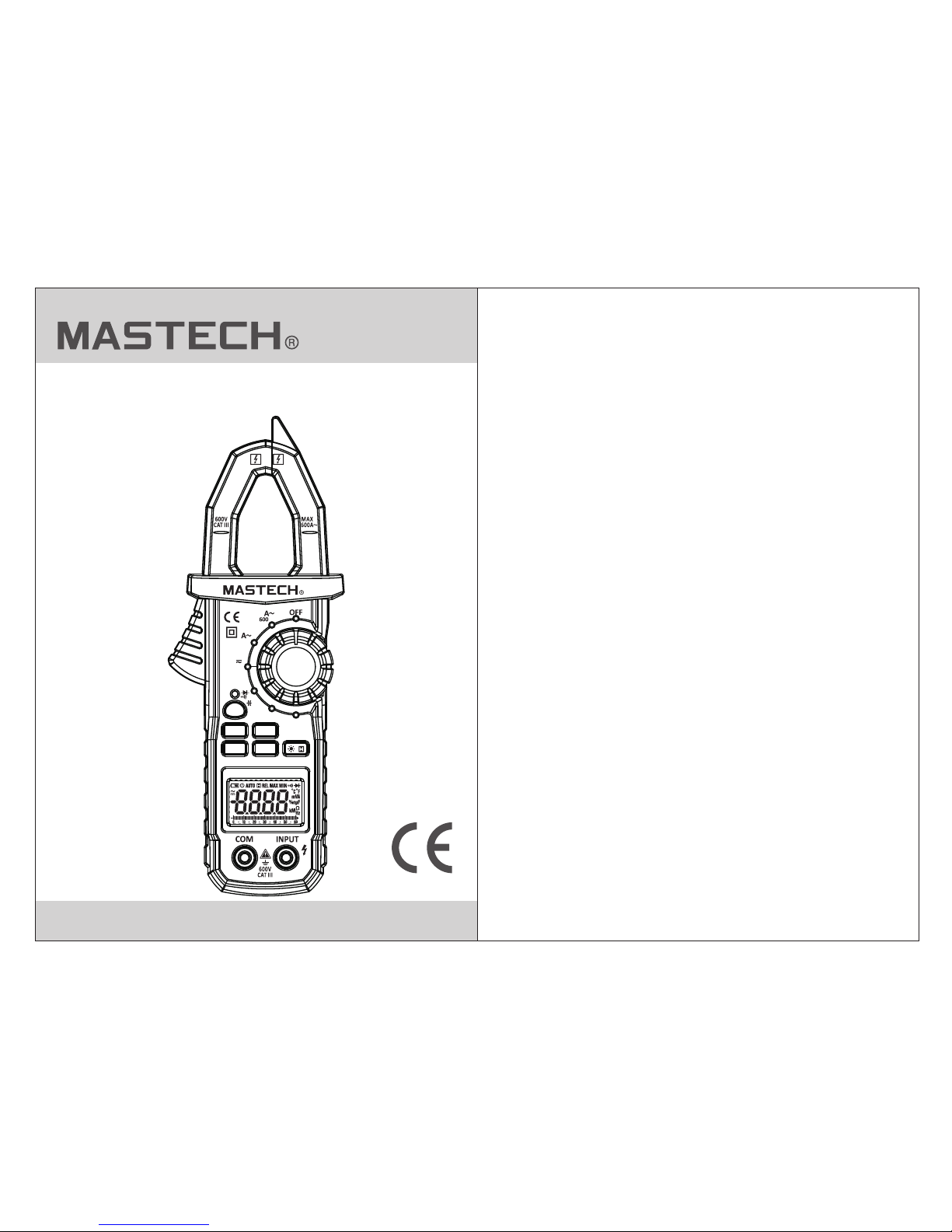
MS2109A
User Manual
AC/DC Clamp Meter
V
Ω
Hz%
TEMP
MS2109A
AC/DC CLAMP METER
NCV
SEL
REL Hz%
MAX/MIN
/
60
Page 2

CONTENTS
1. Safety Information….......................1
1.1 Preparation......................... ..............1
CONTENTS
1.2 Usage................................................2
1.3 Signs and Labels................................3
1.4 Maintenance......................................4
2. Description….................................4
2.1 Part Name..........................................5
2.2 Switch and Button Description..............7
2.3 LCD Display........................................8
3. Specification…...............................9
3.1 General..............................................9
3.2 Technique Data...................................9
4. Operating guidance.......................15
4.1 Reading Hold....................................15
4.2 Measuring Range Switch....................15
4.3 Frequency/Duty Ratio Switch.............15
4.4 Maximum/Minimum
Measurement Choice....................16
4.5 Function Choice..................................17
4.6 Relative Measurement and
Surge Measurement..........................17
4.7 Back Light and Clamp Head Light..........17
4.8 Automati c Power-Off
4.9 Measurement Preparation....................18
4.10 Current Measurement........................19
4.11 Volt age Measurement........................20
4.12 Frequency and
Duty Ratio Measurement
4.13 Resistance Measurement..................23
4.14 Diode Test
4.15 Circuit Co ntinuity test
4.16 Capacita nce Measurement................25
5. Maintenance...................................27
5.1 Replace Battery...................................27
5.2 Replace Probe
6. Accessories....................................27
........................24
........................................24
..................21
............................18
4.17 NCV Measurement............................26
4.18 Temp erature Measurement................26
....................................27
Page 3
01
02
1. Safety Information
1.2 Usage
Please particularly not e that inappropriate use
may cause shock or damage to th e meter. When
using the me ter, comply with common safety
procedur es and complete ly follow the safety
measures in this operatio n manual.
To make full use of the met er's functions and
ensure safe operation, pl ease carefully read and
follow the p rocedures in th e operation manual.
The meter me ets GB/T 13978-92 digital multimeter
general technology cond itions, GB479 3.1-1995 (IEC
61010-1, IEC 61010-2-03 2) electronic m easurement
instrument safety requi rements with secondary pollution
and over-voltage standa rd of CAT III 600V.
Please follow the safety op eration guide lines to ensure
the safe use of meter.
The meter will provide sati sfactory service to you if you
use and protect it appropri ately.
Warning
1.1 Preparati on
1.1.1 When using the meter, the user should comply with
standard s afety rules:
- General sh ock protectio n
- Prevent mi susing the mete r
1.1.2 After r eceiving the meter, please check for d amage
that may hav e occurred duri ng transportation.
1.1.3 If the m eter is stored an d shipped under h ard
conditio ns, please conf irm that the meter is
undamage d.
1.1.4 Probe should be in good c ondition. Bef ore use,
please che ck whether the pr obe insulation is
damaged, w hether metal wi re is bare.
1.1.5 Use th e probe table pro vided with the me ter to
ensure saf ety. If necess ary, replace the probe
with anoth er identical pr obe or one with the same
specific ation.
1.2.1 When using the meter, select the right funct ion
and measur ing range.
1.2.2 Don't measure when ex ceeding the max imum
value in eac h measuring ran ge.
1.2.3 When measuring a circ uit with the meter
connecte d, do not touch the p robe tip (metal part).
1.2.4 When measuring, if th e voltage to be measured
is more than 6 0 V DC or 30 V AC (RMS), always
keep your fi ngers behind th e finger protection
device.
1.2.5 Do not measure voltag e greater than AC 600V.
1.2.6 In the m anual measuri ng range, when th e value
to be measur ed is not known in ad vance, choose
the highes t measuring ran ge to begin, and then
graduall y select lower ra nges until the correct
range is ide ntified.
1.2.7 Befo re rotating con version switch to change
measurin g function, rem ove probe from the
circuit to b e measured.
1.2.8 Don't measure resis tors, capacitors, diodes and
circuits t hat are energiz ed.
1.2.9 During the test of curr ent, resistors, capacitors,
diodes and c ircuit connec tions, do not allow the
meter to con nect with volta ge source.
Page 4

03
04
1.3 Part name
Note (Important safety information. Refe r to the
operation manual).
Dangerous electric conductor.
Double insulation protecti on (cla ss II).
CAT III Ac cordi ng to pul se volt age tol eranc e prote ction
level provided by IEC 61010-1 standard
overvoltage (installation) level III and grade
2 for pollution.
The meter complies with EU standard
Ground (earth)
1.4 Maintenan ce
1.4.1 Don't try to open the meter bottom case to adjust or
repair. Such operations only can be made by
qualified technicians who fully understand the
meter and electrical shock hazard.
1.4.2 Before opening the meter bottom case or battery
cover, remove probe from the circuit to be measured.
1.4.3 To avoid wrong readings and potential electric
shock, when “ ”appears on the meter display,
replace the battery immediately.
1.4.4 Clean the meter with damp cloth and mild
detergent. Do not use abrasives or solvents.
1.4.5 Power off the meter when it is not used. Switch the
transfer switch to OFF position.
1.4.6 If the meter is not used for long time, please take
the battery out to prevent the meter being damaged.
1.2.10 Don't measure capa citance unles s the capacitor
is dischar ged completel y.
1.2.11 Don't use the me ter in explosiv e gas, vapor or
dusty envi ronments.
1.2.12 If yo u find any abnorm al condition or failure on
the meter, stop using the meter and have it
serviced b y a qualified tec hnician.
1.2.13 Unless the meter bot tom case and the battery
cover are co mpletely fast ened in their original
places, do n ot use the meter.
1.2.14 Don't store or use the m eter in direct sunlight,
high tempe rature or high hu midity.
2. Description
- The meter is a portable, professional measuring
instrument with LCD display and back light for easy
reading by users. Measuring range switch is operated
by single hand for easy operation. The meter has
overload protection and low battery indicator. It is an
ideal multifunction meter for professionals, factories,
schools, fans and family use.
- The meter is used to measure AC current, DC current,
voltage, DC voltage, frequency, duty ratio, resistance,
capacitance, circuit connections, diodes, non-contact
voltages and temperatures.
- The meter has an auto measuring range function.
- The meter has a reading hold function.
- The meter has a max. measuring function.
- The meter has a min. measuring function.
Page 5
05
06
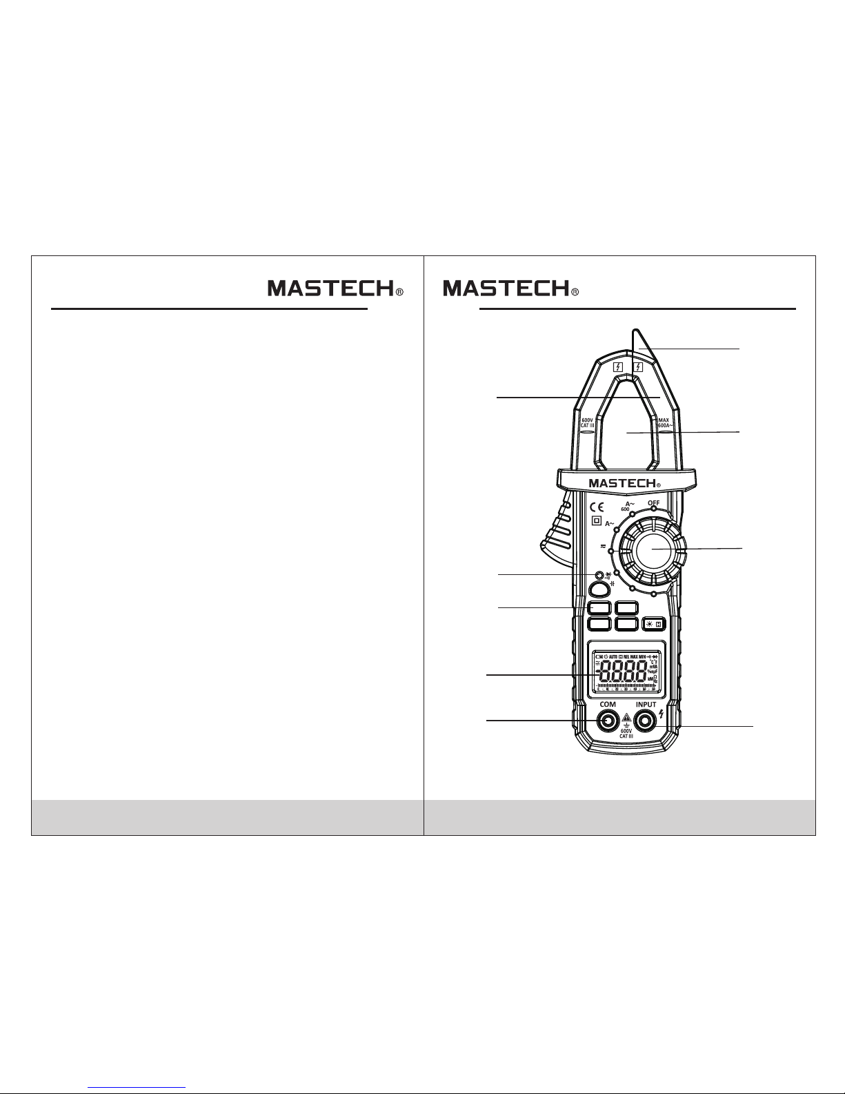
(1) Current clamp head: used for curren t measu remen t.
(2) NCV indicator
(3) Key
(4) LCD display
(5) Common end jack
(6) Resistance, capacitance, voltage, fr equen cy, diode,
continuity and temperature input jack
(7) Knob
(8) Clamp head center position
(9) NCV sense position
2.1 Part name
- The meter has a clamp head frequency measurement
function.
- The meter has an auto power-off function.
- The meter has a relative measuring function.
1
2
3
4
9
6
7
8
5
V
Ω
Hz%
TEMP
MS2109A
AC/DC CLAMP METER
NCV
SEL
REL Hz%
MAX/MIN
/
60
Page 6

07
08
2.2 Switch, But ton and Input Jack Description
B.L/HOLD button: used for reading hold or
back light control
MAX/MIN button: used for maximum/minimum
measurement function switch.
SEL button: used for measuring function swit ch.
NCV button: Non-contact voltage detectio n switc h.
REL button: used for entering relative measu remen t state .
Hz/% button: used for frequency and duty ratio
measurement function switch.
OFF position: used for shutting off t he powe r.
INPUT jack: voltage, resistance, frequen cy, du ty rati o,
capacitance, diode, circuit connection,
temperature measurement input wire
connecting terminal.
COM jack: voltage, resistance, frequency, duty r atio,
capacitance, diode, circuit connection,
temperature measurement common wire
connecting terminal.
Transfer switch: used for selecting functio n and
measuring range.
2.3 LCD Display
ALTERNATING CURRENT, direct current
Diode, continuity
Automatic measuring range mode
Maximum measurement state
AUTO
Minimum measurement state
Relative measurement mode
MAX
MIN
Automatic power-off state
REL
LOW BATTERY
Reading hold state
Percentage (duty ratio)
%
Millivolt, Volt (voltage)
mV, V
A
Amperes (Current)
nF, μF
Nanofarad, Microfarad
Ohm, Kilohm, Megohm (resistance)
Ω,kΩ, MΩ
H
Hz,kHz,MHZ
Hertz, Kilohertz, Megahertz (frequency)
Celsius degree, Fahrenheit degree
(temperature)
°C,°F
Page 7

09
10
3. Specifications
At least once a year, the meter should be reca libra ted
in temperatures of 18°C ~ 28°C and relative humi dity
less than 75%.
3.1 General
Auto measuring range.
Full measuring range overload prote ction .
The maximum allowable voltage betwe en meas ureme nt
end and ground: 600V DC or 600V AC
Operational height: maximum 2000m
Display: LCD
Displayed maximum value: 5999 digit .
Polarity indication: automatic in dicat ion, '- ' means
negative polarity.
Exceeding measuring range di splay : '0L' or ' -0L'.
Sampling rate: about 3 times/s, simulation b ar 30 tim es/s.
Unit display: has function and power un it disp lay.
Auto off time: 1 5 min
Power supply: 1.5V 3AAA battery.
Battery undervoltage indication : LCD dis plays s ymbol .
Temperature coeffic ient: l ess tha n 0.1x ac curacy°C
Operating temperature: 18°C~28°C.
Storage temperature: -10°C~50°C
Dimension: 220×81×41mm
Weigh t: abou t 286g (i nclud e batte ry)
3.2 Technical Indicator s
Environment temperature: 23±5°C, relat ive hum idity
(RH): <75%
3.2.1 AC Current
Measuring
range
Resolution
Accuracy
±(2.5% of reading + 6 digits)
60A
600A
0.01A
0.1A
- Maximum input current: 600A AC
- Frequency range: 40~400Hz
3.2.3 DC Voltag e
600mV
0.01V
0.1V
±(0.7% of reading + 2digits)
6V
60V
600V
0.1mV
0.001V
- Input impedance: 10MΩ
- Maximum input voltage: 600V AC (RMS) or 60 0V DC
3.2.2 DC Current
±(3.0% of reading + 6 digits)
60A
600A
0.01A
0.1A
- Maximum input current: 600A DC
Measuring
range
Resolution
Accuracy
Measuring
range
Resolution
Accuracy
Page 8

11
12
3.2.4 AC Voltage
0.01V
0.1V
±(0.8% of reading + 3 digits)
6V
60V
600V
600V
0.001V
1V
±(1.0% of reading + 4 digits)
- Measuring scope: 40Hz ~ 10kHz
- The inp ut volt age ran ge: > 600 mV AC (RMS ) (inpu t
voltage will increase when the freque ncy to be
measured increases)
- Input impedance: 10MΩ
- Maximum input voltage: 600V AC (RMS)
- Input impedance: 10MΩ
- Maximum input voltage: 600V AC (RMS) or 60 0V DC
- Frequency range: 40 ~ 400Hz
3.2.5 Frequen cy
3.2.5.1Clamp head measuring frequency
(through grade A):
± (1.5% of reading + 5 digits)
99.99Hz
999.9Hz 0.1KHz
0.01KHz
- Measuring scope: 40Hz ~ 1kHz
- The inp ut sign al rang e: > 6A AC (RMS) (input current
will increase when the frequency to be me asure d
increases)
- Maximum input current: AC 600A (RMS)
3.2.5.3 Through grade HZ/DUTY:
9.999Hz
±(0.5% of reading + 3 digits)
99.99Hz
0.001KHz
0.01Hz
0.001Hz
0.1Hz999.9Hz
9.999KHz
99.99KHz
999.9KHz
9.999MHz 0.001MHz
0.1KHz
0.01KHz
- Overload protection: 250V DC or AC (RMS)
- The inp ut volt age ran ge: > 2V (i nput vo ltage w ill
increase when the frequency to be measu red
increases)
Note:
In the small voltage measuring range, t he prob e is not
connected with the circuit to be tested, and the m eter
may have fluctuating readings. Th is is nor mal and
caused by the meter's high sensitivit y. It do es not
affec t actua l measu remen t resul ts.
Measuring
range
Resolution
Accuracy
Measuring
range
Resolution
Accuracy
± (1.5% of reading + 5 digits)
99.99Hz
999.9Hz
0.1Hz
0.01Hz
Measuring
range
Resolution
Accuracy
9.999kHz
0.001KHz
3.2.5.2 Through grade V:
Measuring
range
Resolution
Accuracy
Page 9

13
14
Resolution
Accuracy
600Ω
6kΩ
0.1kΩ
0.001kΩ
0.1Ω
0.01kΩ
0.1MΩ
0.001MΩ
Function
0.001V
If the resistance of circuit to be
measured is less than 70Ω, the
meter's built-in buzzer may sound.
3.2.6.2 Through grade V:
- Frequency response: 40 ~ 10kHz
- Input voltage range: > 600mV AC
- Input impedance: 10MΩ
- Maximum input voltage: 600V AC (RMS)
3.2.6.2 Through grade HZ/DUTY:
- Frequency response: 1 ~ 10MHz
- The inp ut volt age ran ge: >2V AC ( RMS) (i nput
voltage will increase when the freque ncy to be
measured increases)
- Maximum input voltage: 250V AC (RMS)
3.2.7 Resistance
60kΩ
600kΩ
6MΩ
60MΩ
±(1.2% of reading + 3 digits)
- Open circuit voltage: about 0.4V
- Overload protection: 250V DC or AC (RMS)
3.2.8 Circuit Continuity Test
- Overload protection: 250V DC or AC (RMS)
0.1Ω
Display approximate diode
forward voltage value
3.2.10 Diode Test
- Forward DC current is about 1mA
- Backward DC voltage is about 3.3V
- Overload protection: 250V DC or AC (RMS)
Accuracy
40nF
±(4.0% of reading + 5 digits)
0.01μF
0.1nF
0.01nF
0.001μF
0.001mF
0.1μF
3.2.9 Capacitance
4μF
- Overload protection: 250V DC or AC (RMS)
400nF
40μF
400μF
4000μF
3.2.6.1Through grade A (from clamp head):
- Frequency response: 40 ~ 1kHz
- Input current range: >6A AC (RMS)
- Maximum input current: AC 600A
3.2.6 Duty Ratio
Measuring range
Resolution
Accuracy
0.1%-99.9% 0.1%
±(3%+5)
Measuring range
±(0.8% of reading + 3 digits)
Measuring
range
Resolution
Measuring
range
Resolution
Measuring
range
Resolution Function
Page 10

15
16
4. Operating Guidance
1) In the process of measurement, if reading hol d is
required, press “HOLD/B.L” key. The display value
in the display will be locked. Press “HOLD/B.L ”
key again to release reading hold.
4.1 Reading Hold
4.2 NCV Key
NCV key is used for non-contact voltage d etect ion.
Press this key and hold it. Place the NCV sensor
zone close the conductor to be detected . It volt age
is more than AC 90V, NCV in dicat or will f lash an d
the buzzer will sound at regular interv als.
4.3 Frequency/Duty Ratio Switch
1) When the meter is in AC vol tage, AC current posit ion,
if “Hz/%” button is pressed, the meter will measure
AC voltage and AC current signal frequenc y. Cli ck
“Hz/%” button again, and the meter will measur e
voltage and current signal duty ratio. If it is in
HZ/DUTY posi tion, p ressi ng HZ % key w ill swi tch
between HZ and DUTY.
4.4 Maximum/Minimum Measurement Choice
1) Press “MAX/MIN” key to enter MAX mode, and
always store measurement maximum value. Pr ess
“MAX/MIN” key again, and the meter will enter
minimum value measurement state. Press
“MAX/MIN” key for the third time, and the meter
will display the diff erenc e of maxi mum and m inimum
value. Press “MAX/MIN” key to cycle through the
above operations.
2) After entering MAX or MIN mode, the meter will
automatically save the measured maximum or
minimum value.
3) If the user presses “MAX/MIN” key more than 2 sec,
the meter will restore normal measuring rang e.
1) When the meter is in the maximum/minimum valu e
measurement state, it is manual measuring ra nge
mode.
2) When the meter is in the frequency, dut y ratio
measurement state, it can't be switched to
maximum/minimum value measureme nt mode .
3) When the meter is in the maximum/minimum valu e
measurement state, SEL, REL key is invalid.
Note:
3.2.11 Temperature
Measuring
range
Resolution
Accuracy
-20°C~0°C
±(3.0% of reading + +4 digits)
1°C~400°C
401°C~1000°C
1°C
±(1.0% of reading + +3 digits)
±2.0% of reading
Note:
When the meter is in the maximum/minimum value
measurement state, it can't be switched to fre quenc y,
duty ratio measurement mode.
2) If “Hz/%” button is pressed again, the meter wi ll
revert to voltage, current measurement state.
- Temperature indicator does not include thermocouple error.
- Overload protection: 250V DC or AC (RMS)
Page 11

4.5 Function Switch
1) In the resistance mode, pressing “SEL” butt on will
switch among resistance, diode, continui ty and
capacitance detection.
2) In the voltage and current mode, pressing “SE L” key
will switch between AC a nd DC.
3) In the temperature mode, pressing “SEL” key w ill
switch between Celsius degree and Fah renhe it
degree.
17
18
1) REL key is relative value measurement button. When
the user taps this button, it will enter relative value
measurement mode. The curr ent dis play va lue can
be stored in the memory as reference value. When
the user measures later, the display value is the
diffe rence f or inpu t value m inus re feren ce valu e. ie.
REL∆(current reading)= Input value - Refer ence va lue.
2) The re lativ e value m easur ement c an only b e
performed in the manual measuring mod e.
4.6 REL Measurement
4.7 Back Light And Clamp Head Light
1) In the process of measurement, if ambient lig ht is too
dark to read, press “B.L/HOLD” key for more than 2
seconds to turn on the backlight. The b ackli ght wil l
automatically turn off in ab out 10 se conds .
2) During this period, pressing “B.L/ H OLD” ke y more
than two seconds will turn off b ackli ght.
3) In the current measuring mode, the meter will t urn
on backlight. At the same time it will turn on clamp
head light. Backlight luminophor is L ED with h igh
current draw. If backlight is used often, it will shorte n
battery life. There fore, u se the ba cklig ht only w hen
necessary.
4.8 Automatic Power-Off
1) If there is no operation for 15 minutes after turning
the machine on, the meter will automatically power
off to save electricity. Within 1 minute before
shutdown, the buzzer will sound for five times. Just
before powering off, the buzzer will make a long sound.
2) After automatic power-off, press any key to restore
the meter to ready status.
3) Holding the “SEL” key when powering on will cancel
automatic power-off function.
Note:
When battery voltage is <3.6V, LCD displays “ ”
(undervoltage) symbol.
But when the user uses the backlight, whe n the bat tery
voltage frequency is >3.6V, batt ery vol tage dr ops due
to its high working current, “ ” symbol may displa y.
(When “ ” symbol shows, it does not guarantee the
accuracy of measurement). At this time, don't r eplac e
the battery. Us e the met er norm ally wi thout u sing
back light, and wait to replace the batte ry when t he
“ ” symbol is displayed.
4.9 Measurement Preparation
1) Turn the transfer switch to turn on the power. When
battery voltage is low (about <3.6V), LCD displays
“ ” symbol, replace the battery.
2) “ ” symbol means that input voltage or current
should not be more than instruction value, which is
to protect the internal line from damage.
3) Place transfer switch to required measuring function
and range.
4) When connecting line, please connect the common
test line first, then connect charged test line.
When removing line, remove charged test line first.
Page 12

19
20
1) Clamping two or more leads of circuit to b e teste d
simultaneously will give invalid re ading s.
2) To get acc urate r eadin gs, pla ce the le ad to be
tested at the center of clamp head.
3) “ ”indicates that maximum input AC current is 60 0 A.
4) To impro ve meas ureme nt prec ision , in the DC
current measurement state, because the ear th and
other magnetic fields have an impact on DC curre nt
measurement precision, if the LCD display is n ot
zero, place the clamp head vertical to conduct or to
be measured, then press REL back to zero, then
measure.
4.11 Voltage Measurement
Note:
Electric shock hazard.
Pay special attention to avoid shock when
measuring high voltage.
Don't input voltage more than AC 600 V RMS.
Warning
1) Insert black probe to COM jack, insert red prob e to
INPUT jack, choose appropriate measuring r ange.
2) Place transfer switch in voltage pos ition At
this time, the meter is DC voltage measurement
state. To measure AC vol tage, p ress SE L key to
enter AC v oltag e measu rement state.
3) Connect the probe with voltage sourc e or both
ends of load in parallel.
4) Read the voltage on the LCD.
Note:
1. In the small voltage measuring range , the pro be is
not connected with the circuit to be tested, and t he
meter may have fluctuating readings. Thi s is norm al
and is caused by the meter's high sensitivity. When
the meter is connected with the circuit to be tested,
you will get actual measured value.
2. “ ”indicates that maximum input voltage is 60 0V
AC or 600V DC.
3. If the reading measured by the meter is more than
750V AC or 1000V DC, it will send out “beep” ala rm.
4.10 Current Measurement
Electric shock hazard.
Remove the probe from the meter before
measuring with current clamp.
1) When measuring switch is placed to pos ition A , the
meter is in AC current measurement state. Choos e
the appropriate measuring range. If you can' t
determine the size of current to be tested, choose
the maximum measuring range, then choose low er
ranges until the correct range is displayed. I f you
want to measure DC current, press SEL key to enter
DC current measurement state.
2) Hold the trigger, open clamp hea d, and cl ip one le ad
of measurement circuit to be tested into the cla mp.
3) Read the duty ratio value on the LCD displ ay.
Warning
V
Page 13

21
22
4.12 Frequency And Duty Ratio Measurement
Electric shock hazard.
Remove the probe from the meter before
measuring with current clamp.
Warning
(1) Place masuring switch nposition A . Choos e
appropriate measuring range.
(2) Hold the trigger, open clamp head, cli p one lea d of
measurement circuit to be tested in the clamp.
(3) Press “Hz/%” key to switch to frequency
meauring state.
(4) Read the current value on the LCD displ ay.
(5) Pressing “Hz/%” again can enter dut y ratio
measuring state.
(6) Read the current value on the LCD displ ay.
Note:
(1) Clamping two or more leads of circuit t o be test ed
simultaneously will give invalid re ading s
(2) Frequency measurement range is 40 Hz~1k Hz
If the frequency to be tested is less than 40Hz,
measuring frequency higher than 10 kH z is poss ible,
but accuracy is not guarantee
(3) Duty ratio measuring range is 10~95 %.
(4) “ ” means that maximum input current is 600A
AC (RMS).
1) Clamp head measuring frequency
(through grade current):
2) Through grade voltage:
Electric shock hazard.
Pay special attention to avoid shock when
measuring high voltage.
Don't input voltage more than AC 600V RMS.
Warning
(1) Insert black probe to COM jack, insert red pro be
to INPUT jack.
(2) Place transfer switch to position, press SEL to
enter AC v oltag e measu rement state.
(3) Press “Hz/%” key to switch to frequency
measuring state.
(4) Connect the probe with signal or both e nds of
load in parallel
(5) Read on the LCD.
(6) Pressing “Hz/%”again to enter dut y ratio
measuring state and read data on the LCD.
V
(1) Frequency measurement range is 10 Hz ~ 1kHz I f
the frequency to be tested is less than 10Hz,LCD
will show “00.0”measuring frequen cy high er than
10 kHz is possible, but it accuracy is not guarant ee
(2) Duty ratio measuring range is 10 ~ 95%.
(3) “ ”means that maximum input voltage is 600V
AC (RMS).
Note:
Page 14

24
3) Through grade HZ/DUTY:
Electric shock hazard.
Pay special attention to avoid shock when
measuring high voltage.
Don't input voltage more than AC 250V RMS.
(1) Insert black probe to COM jack, insert red pro be to
INPUT jack.
(2) Place transfer switch in position H Z.
(3) Connect the probe with signal or both e nds of lo ad
in parallel.
(4) Read on the LCD.
(5) Press “Hz/%” again to enter duty ratio measu ring
state.
Warning
Note:
Frequency measurement range is 1 Hz~1 0 MHz. If t he
frequency to be measured is less than 1 Hz, the LCD
will display “00.0”.
4.13 Resistance Test
Electric shock hazard.
When measuring circuit impedance, determine
that the power supply is disconnected and the
capacitor in the circuit is completely discharged.
Warning
1) Insert black probe to COM jack, insert red prob e to
INPUT jack.
2) Place measuring range switch to position. At
time, the meter is in the measurement state.
3) Connect the probe to the both ends of resi stor or
circuit to be tested..
4) LCD will show readings.
23
Ω
Note:
1) When the input end is open, LCD shows “0L”
over-range state.
2) When the resistance to be tested is >1MΩ, the meter
reading will stabliize after a few seco nds, wh ich is
normal for high resistance readings .
4.14 Diode Test
1) Insert black probe to COM jack, insert red prob e to
INPUT jack.
2) Place measuring switch in position.
3) Press “SEL” button to switch to measuring state.
4) Connect the red probe to diode anode and c onnec t
the black probe to diode cathode to make test.
5) Readings will display on the LC D.
Ω
Note:
1) What the meter shows is approximation of diod e
forward voltage drop.
2) If the probe has reverse connection or the prob e
is open, the LCD will show “0L”.
4.15 Circuit Continuity Test
Electric shock hazard.
When measuring circuit continuity, dete rmine
that the power supply is disconnected and the
capacitor in the circuit is completely discharged.
Warning
1) Insert black probe to COM jack, insert red prob e to
INPUT jack.
2) Measuring switch is placed to position.
3) Press “SEL” key to switch to circuit continuity
measuring state.
Ω
Page 15

25
26
Note:
If the probe is open or circuits resistance to be te sted
is more than 600Ω, the display will show “0 L”.
4.16 Capacitance Measurement
4) Connect the probe to the both ends of circ uit to
be tested.
5) If the resistance of circuit to be measured is le ss
than 70Ω, the meter's built-in buzzer may sound.
6) Read the circuit resistance value on t he LCD.
Electric shock hazard.
To avoid e lectr ic shoc k, befo re meas uring
capacitance, discharge capacitance com plete ly.
Warning
1) Insert black probe to COM jack, insert red prob e to
INPUT jack.
2) Measuring switch is placed to position
3) Press “SEL” button three times to switch to
capacitance measuring state.
3) After discharging capacitance com plete ly, connect
the probe to the both ends of capacitor to be tested
for measurement.
4) Read the capacitance on the LCD.
Ω
Note:
1) When measuring bulk capacitor, read ings wi ll
stabilize after a few seconds (400μF and 4000μ F).
2) To impro ve the ac curac y below 4 0nF mea surin g
value, subtract the distributed capacita nce of me ter
and cable.
4.17 NCV Measurement
1) Press NCV key. .
2) Place the NCV sensor zone close to the con ducto r.
When test voltage is greater than AC 110V (RMS),
when the meter is close to the conductor, the meter
induction voltage indicator will tu rn on and b uzzer
will sound.
Note:
1: Even there is no indication, voltage m ay exis t still .
Don't use non-contact voltage detector to ju dge
whether there is voltage in the wire. Detectio n
operation could be affecte d by sock et desi gn,
insulation thickness, type and other facto rs.
2: When inputting voltage on the meter in put ter minal ,
due to the existence of the induced voltage, vol tage
induction indicator also may light.
3: Interference sources of external enviro nment ( such
as flashlight, motor, etc.) may trigger inval id
non-contact voltage detection.
4.18 Temperature Measurement
1) Insert black probe to COM jack, insert red prob e to
INPUT jack.
2) Rotate switch to “TEMP” position. Normal
temperature will show on the LCD displa y
simultaneously.
3) Insert K-type thermocouple to the input jac k of the
meter with correct polarity (insert red one to INPUT
jack, and insert black one to COM jack).
4) Measure the inner and outer surfaces o f objec t to
be tested with the measuring end of thermocoup le.
5) Read the measuring value from LCD disp lay.
Page 16

27
Before opening the meter battery cover,
remove probe from the circuit to be measured
to avoid electric shock.
Warning
1) When the battery indicator “ ” appears, the battery
should be replaced immediately.
2) Unscrew the fastening screw and remo ve the me ter
battery cover.
3) Replace battery.
4) Put the battery cover back as before.
5. Maintenance
5.1 Replace Battery
Note:
Do not reverse the battery connection s. Do not r eplac e
battery when the meter is turned on.
5.2 Replace Probe
When replacing probe, use an identical probe
or one with the same specification. The probe
should be in good condition, with a capacity
of 1000V, 10A.
Warning
If the probe is damaged, such as having a bar e metal
wire, replace the probe.
6. Accessories
1) probe Level:1000V 10A One pa ir
2) User Manual 1 pc
3) Battery 6F22 9VOLTS
HYS007092
 Loading...