

Page 1
MS2030B
AC Digital Clamp Meter
User’s Manual
AUTO
RS232
CAT III
600 V
Page 2

CONTENTS CONTENTS
2.Safety Information.................................1
2.1 Precautions ........... ..... ...................... ..... 1
2.2 Safety Symbols........ ........................ ..3
3. Description.................................... .......4
3.1 Front Panel .......................... ...............4
3.2 Display .............. ........................ .......7
4. Using the Meter .................................8
4.1 Data Hold .............. ........................ ....8
4.2 Manual Range ........... ........................ 8
4.3 Auto Power Off ............................... ...8
1.Introduction ........... ........................ .......1
4.4 DC Voltage............. ........................ ....8
5. Specifications ..................................13
5.2 Technical Spec ifications.............. .......14
5.1 General Specifications.......................13
6. Maintenance.....................................18
4.5 AC Voltage............. ........................ ....9
4.6 AC Current ............. ...........................9
4.7 Resistance ........... ........................ ....10
6.2 Replacing the Batteries......................19
6.1 General Main tenance ............................18
6.3 Replacing Test Leads............... ..........19
7. Acce ssories .....................................20
4.9 Continuity ...................... .....................11
4.10 Capa citan ce......................................12
4.11 Tempera ture .....................................12
4.13 NCV (Non-Co ntact Voltage) ..................13
4.8 Diode Test....................................... ....11
4.12 Frequency /Duty C ycle ........................12
Page 3
01 02
1.Introduction
The meter is a safe, reliable, yet small handheld 3 ¾ digital
clamp meter. Capable of measuring AC current, AC/DC
voltage, resistance, capacitance, temperature, frequency/
duty cycle, NCV, diode’s forward voltage drop, and continuity,
it’s ideal for both home users and professionals.
2.1 Precaution s
2.Safety Instru ctions
The meter is designed and manufactured according
to safety requirements of EN 61010-1:2010,
EN 61010-2-032:2012, EN 61010-2-033:2012 on electronic
measuring instrument and hand held digital multipurpose
meter. And conforms to UL STD.61010-1,61010-2-032,
61010-2-033, Certified to CSA STD.C22.2 NO.61010-1,
61010-2-032,61010-2-033.The product meets with the
requirements of 600V CAT III and pollution degree 2.
• All safety guidel ines outlined should be follow ed
otherwise the pr otect ion provided by the instr ument
may be impaired.
• Warning symbols in the manua l alert u sers of potential
dangerous situ ations.
• Precautions ar e to prev ent the user from damagin g
the instrument o r the tes t object.
To avoid poss ible el ectric shock, personal injur y or
damage to the mete r, please observe the following :
3. Ensure the mete r works p roperly by testing a know n
voltage first. I f not wor king properly, have th e meter
serviced befor e using .
4. Never exceed th e prote ction limit values indi cated
in the specifica tions f or each range of measurem ent.
5. Always use cauti on when making voltage
measurements a bove 60 V dc or 30V ac rms.
6. Make sure to use th e corre ct input jack, function a nd
range when measu ring.
7. Do not place the me ter in an y environment with dust ,
explosive gas or v apor.
8. Always keep fing ers behind the probe barriers.
9. Connect the com mon tes t lead first, then the hot le ad.
Disconnect in re verse o rder.
10. Turn off power and discharge capacit ors bef ore
measuring resi stanc e, diodes or continuity.
11. Fail ure to fo llow safety guideline s may pre vent the
meter’s built in protecti on from w orking properly.
12. To avoid d amage o r incorrect readings, c heck fo r AC
voltage presen t befor e making DC voltage
measurements .
13. Do not use the met er with t he battery cover not
securely in plac e.
14. When the “ ”symb ol appe ars, replace the batter ies
to avoid incorre ct read ings
15. Before openi ng the case, always disconnect t est
leads from all ene rgize d circuits.
16. Only use the tes t leads p rovided with the meter.
Replace only wit h simil ar leads with matching
specificatio ns.
17. Do not touch inp ut jack s during measurement to
avoid electric s hock.
18. Before switc hing fu nctions, remove test le ads fro m
an circuit.
1. Before using th e meter, c heck the meter for damage
during transpo rt.
2. Check the test le ads for d amage to the insulation o r
wires before use .
Make sure to read and follow all safety procedures to
avoid electric shock and/or injury. If the equipment
is used in a manner not specified by the manufacturer,
the protection provided by the equipment may be
impaired.
WARNING
Page 4
AUTO
RS232
03 04
2.2 Safety Symbo ls
3. Description
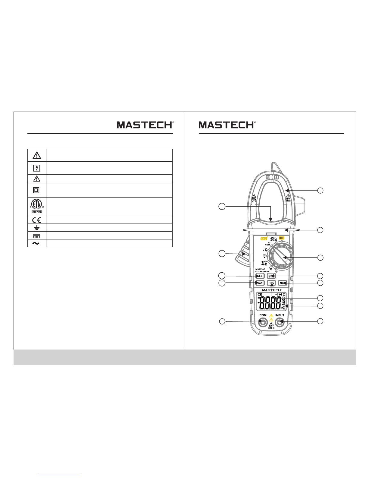
3.1 Front Panel
1
2
3
4
5
6
7
8
9
10
11
12
13
Note-Impor tant sa fety in formation, refer to the
instructio n manua l.
Conforms to UL STD. 61010-1, 61010-2-032,
61010-2-033; Certified to CSA STD C22.2 NO.
61010-1, 61010-2-032,61010-2-033
Complies wit h Europ ean (EU ) safety standards
Earth (groun d) TERMINA L
Caution, pos sibil ity of el ectric shock
Equipment pr otect ed thro ughout by double
insulation o r reinf orced i nsulation.
Application around and removal from UNINSULATED
HAZARDOUS LIVE conductors is permitted.
Direct curre nt
Alternating c urren t
CAT III: MEASUREMENT CATEGORY III is applicable to
test and measuring circuits connected to the distribution
part of the building's low-voltage MAINS installation.
CAT II: MEASUREMENT CATEGORY II is applicable to test
and measuring circuits connected directly to utilization points
(socket outlets and similar points) of the low-voltage MAINS
installation.
CAT IV: MEASUREMENT CATEGORY IV is applicable to
test and measuring circuits connected at the source of the
building’s low-voltage MAINS installation.
Page 5

05 06
1. Current Clamp
For measuring AC cu rrent .
2. Safety barrie r
Helps to keep hand s from to uching conductors whi le
measuring curr ent.
3. Rotary Switch
Used to select fun ction a nd range.
/
Hold the
button to turn on th e backl ight.
The worklight wi ll turn on as well when the rotary
switch is in one of th e curre nt positions. Hold down
the button again t o turn off the backligh t.Pre ss the
/
button and the dis play will keep the reading on
the screen. The
“
”
symbol appears o n the display.
Press the “HOLD” b utton a gain to return the displa y
to normal.
4.Backlight/ Hold bu tton
5. NCV Button
Hold the “NCV” but ton to ac tivate the non-contac t
voltage mode.
6. Frequency/D uty Cyc le Button
Press the “Hz%” bu tton wh ile in voltage mode to
switch to freque ncy mod e. Press the button again
to switch to duty cy cle mod e. Press the button a
third time to retu rn to vol tage mode.
7. Display
ax. display valu e: 3999
8. Input Jack
Connection for t he live ( red) test lead for voltag e,
resistance, ca pacit ance, diodes and contin uity.
9. COM Jack
Connection for t he comm on (black) test lead.
10. Range Button
Press the “RAN” bu tton to s witch to manual range.
Each press incre ases th e range and returns to the
lowest range whe n pressed in the highest range.
Hold the button to r eturn t o auto-range.
11. Select Button
Press “SEL” to swi tch bet ween AC/DC voltage and
between functi ons in th e multi-function posi tion.
12. Clamp Trigger
Press the trigge r to open t he clamp jaw; release
to close.
13. Wor kligh t
When the rotary sw itch is i n one of the current
positions and th e backl ight is turned on, the work light
will also turn on.
Page 6

08
4. Using the Meter
4.1 Data Hold
The data hold func tion will keep the current readi ng on
the display. To activate data hol d:
1. Press the “ / ” butto n and the r eading will be held
on the display. The“ / ”symbol appears.
2. Press “ / ” again to re lease t he hold.
nF, µF, mF
Ω, kΩ, MΩ
Symbol
Description
Celsius/Fahre nheit
Farads (capaci tance )
Ohms (resistanc e)
Diode
Display H old
Polarity Indic ator (N egative)
Auto-range
AUTO
Low Battery
°C°F
%
Percentage (du ty cycl e)
Hz, kHz
Hertz (frequen cy)
MV,V
Volts (Volt age)
µA, mA,A
Amps (Current)
Continu ity
4.2 Manual Range
The meter ’s default range i s “AUTO.” To sel ect man ual
range, press “RA N” to ent er manual range. Each pre ss
of the button incr eases t he range and returns to the
lowest range whe n pressed at the highest range. Ho ld
the button to retu rn to aut o-range. Manual range c annot
be used in 40 A and 4A curre nt mode s, frequency, duty
cycle, diode, co ntinu ity, or tempera ture mo des
4.3 Auto Power Off
If the meter is not used for approx. 30 min., the meter will
automatically turn itself off to conserve battery power. To turn
the meter back on after auto off, press the “SEL” button.
07
4.4 DC Vol tage
1. Insert the red te st lead i n the “INPUT” jack and the
black lead in the “C OM” jac k.
2. Move the rotary s witch t o the“ ”position.
The def ault mo de is DC voltage. Connect t he test
leads across the c ircui t or load to be measured.
3. Read measured v oltage on the display.
Use extra c autio n when me asuring high voltages
to avoid electri c shock o r damage.
CAUTION
Do not attempt to me asure v oltages above
600V DC to prevent i njury o r damage to the meter.
WARNING
V
3.2 Display
AUTO
RS232
Direct Current
Alternating Cur rent
Page 7

09 10
4.5 AC Voltage
1. Insert the red te st lead i n the “INPUT” jack and the
black lead in the “C OM” jac k.
2. Move the rotary s witch t o the“ ”position.
Press “SEL” to swi tch to AC vo ltage. Connect the test
leads across the c ircui t or load to be measured.
3. Read measured v oltage on the display.
Use extra c autio n when me asuring high voltages
to avoid electri c shock o r damage.
CAUTION
Do not attempt to me asure v oltages above
600V AC to prevent injury or dam age to th e meter.
WARNING
4.6 AC Current
1. Move the rotary s witch t o the position with the
proper range.
2. Press the trigg er to ope n the clamp and insert one
conductor insi de the ja ws. Only clamp one conduc tor;
multiple condu ctors w ith differen t curre nt directions
will cancel out re adings.
3. Read measured c urrent on the display.
1.If the current r ange is n ot known before hand,
set the range to the h ighes t range and adjust
down as necessar y.
2.When measuri ng bare w ires, use extra caution t o
avoid electric s hock.
CAUTION
- When leads are dis connected or measurement is ou t
of range, “OL” is di splay ed.
Tips for measuring resista nce:
- Sometimes the re sisto r value and measured resi stanc e
diffe r.This is due to the meter’s output test curre nt goes
through all poss ible paths between leads.
- For low resistan ce meas urements, short the tes t leads
and record the res istan ce displayed. Then co nnect to
the circuit and su btrac t the recorded resistan ce from
the measuremen t for the m ost accurate results.
To avoid i njury o r damage to the meter, make su re
to turn off all powe r and dis charge all capacitors
before measuri ng resi stance.
WARNING
4.7 Resistance
1. Turn off all power and discharge capaci tors on t he
circuit under te st.
2. Insert the red te st lead i n the “INPUT” jack and the
black lead in the “C OM” jac k.
3. Move the rotary s witch t o the position. Connect
the test leads acr oss the c ircuit to be measured.
4. Read measured r esistance on the display.
Ω
V
Page 8

11 12
To avoid i njury o r damage to the meter, make su re
to turn off all powe r and dis charge all capacitors
before measuri ng diod es.
WARNING
4.9 Continuity
1. Turn off all power and discharge capaci tors on t he
circuit under te st.
2. Insert the red te st lead i n the “INPUT” jack and the
black lead in the “C OM” jac k.
3. Move the rotary s witch t o the position. Press
“SEL” twice to swi tch to co ntinuity mode. Connec t
the test leads acr oss the c ircuit to be measured.
4. Read measured r esistance on the display. If th e
measured resis tance i s less than 60Ω, the meter’s
buzzer will soun d.
To avoid i njury o r damage to the meter, make su re
to turn off all powe r and dis charge all capacitors
before measuri ng cont inuity.
WARNING
4.10 Capacitan ce
1. Turn off all power and discharge capaci tors on t he
circuit under te st.
2. Insert the red te st lead i n the “INPUT” jack and the
black lead in the “C OM” jac k.
3. Move the rotary s witch t o the position. Press
“SEL” three time s to swit ch to capacitance mode.
Connect the test l eads ac ross the circuit to be
measured.
4.Read measure d capacitance on the display.
4.11 Temp erature
1. Move the rotary s witch t o the “°C” or “°F” position .
The display will s how the current ambient temper ature .
2. Connect the red e nd of the i ncluded type-k
thermocouple t o the “IN PUT” jack and the black end
to the “COM” jack.
3. Touch th e tip of the thermocouple to the obj ect to be
tested.
4. Read measured r esistance on the display.
4.12 Frequency /Duty C ycle
1. Insert the red te st lead i n the “INPUT” jack and the
black lead in the “C OM” jac k.
2. Move the rotary s witch t o the position. While in
voltage mode, pr ess “Hz %” to switch to frequency
mode. Connect th e test le ads across the circuit to
be measured.
3. Read measured r esistance on the display.
4. Press “Hz%” aga in to swi tch to duty cycle mode.
Connect the test l eads ac ross the circuit to be
measured.
5. Read measured d uty cyc le on the display.
6. Press “Hz%” to re turn to v oltage mode.
Ω
Ω
Ω
4.8 Diode Test
1. Turn off all power and discharge capaci tors on t he
circuit under te st.
2. Insert the red te st lead i n the “INPUT” jack and the
black lead in the “C OM” jac k.
3. Move the rotary s witch t o the position. Press
“SEL” to switch to d iode mo de. Connect the test
leads across the c ircui t to be measured.
4.Read the measu red forward biased voltage dro p on the
display. If the l eads are reversed, only “ 1” is dis played.
Ω
Page 9

13
14
Note:
1. Even if no indica tion is g iven, voltage may still b e
present. Do not re ly sole ly on NCV detection to
determine the pr esenc e of voltage.
2. When measurin g AC/DC voltage, the NCV indicato r
may flash due to ind uced vo ltage.
3. External powe r sourc es/interference may t rigge r the
NCV indicator.
5. Specifications
5.1 General Spec ifica tions
• Safety rating: CAT III 600V, pollution degree 2
• Max. operating altitude: 2000m
• Operating temperature: 0~40°C, <80% RH
• Storage temperature: -10~60°C, <70% RH
(battery removed)
• Temperature coefficient: 0.1 accuracy/°C
(<18°C or >28°C)
• Max. voltage between terminals and
ground: 600V DC or AC rms
• Sample rate: approx. 3 times/sec
• Display: 3 ¾ digit LCD (max. display: 3999)
• Over-range indication: display only shows “OL”
• Low battery indication: when battery voltage drops below
operating voltage,“ ”symbol appears on the display
• Polarity indication: automatically displays “-“
• Power: 3x 1.5V AAA batteries
• Dimensions: 198mmX79mmX38mm
• Weight: approx. 196g (with battery)
• Max. jaw opening: 26mm
±(0.8% of readin g+3 digits)
5.2 Tech nical S pecifications
Accuracy: ±(% of r eadin g + digits), 1 year warrant y.
Ambient temp: 18 °C~28 °C, humidity: <75%.
Temperature coefficient: 0.1accur acy/° C
(0°C~18°C or 28°C~40° C)
For AC current measu remen t, keep the conductor in the
center of the clam p; othe rwise the reading can dev iate
as much as 1.5% of act ual mea surement.
5.2.1 DC Voltag e
- Input impedanc e: 10M
- Overload prote ction : 600V DC or AC rms
- Max. input volta ge: 600 V DC
400mV 0.1mV
Range
Resolution
Accuracy
mark
mark
mark
conductor
600V
1V
4V
1mV
40V 10mV
400V 0.1V
4.13 NCV (Non-Co ntact Voltage)
1. Move the rotary s witch t o any position.
2. Hold the “NCV” bu tton an d move the tip of the
clamp close to the t est obj ect. If the detected volt age
is >110V AC , the met er will beep and the NCV indi cator
will flash.
Page 10

15
16
- Input impedanc e: 10MΩ
- Overload prote ction : 600V DC or AC rms
- Max. input volta ge: 600 V DC
±(1.0% of readin g+5 digits)
- Frequency rang e: 40Hz ~400Hz
- Response: Average; calibrated to rms s ine wav e
5.2.2 AC Voltage
400mV 0.1mV
Range
Resolution
Accuracy
600V
1V
4V
1mV
40V 10mV
400V 0.1V
±(2. 5% of reading+5 di gits)
5.2.3 AC Current
4A
0.001A
Range
Resolution
Accuracy
40A 0.01A
400A 0.1A
600A
1A
- Frequency rang e: 50Hz~60Hz
- Max. input curre nt: up to 1 20% of full scale for no more
than 60 seconds.
- Response: Average; calibrated to rms s ine wav e
- Open circuit vol tage: a pprox. 0.4V
- Overload prote ction : 250V DC or AC rms
5.2.4 Resistan ce
±(1.0% of readin g+5 digits)
400Ω 0.1Ω
Range
Resolution
Accuracy
4KΩ 1Ω
40KΩ 10Ω
400KΩ 0.1KΩ
4MΩ 1KΩ
40MΩ 10KΩ
±(2. 0% of reading+5 di gits)
Range
Resolution
Accuracy
5.2.5 Diode Tes t
0.001V
Shows app rox.
forward biased v oltage drop
- Forward DC curre nt: app rox. 1mA
- Reverse DC volta ge: app rox. 1.5V
- Overload prote ction : 250V DC or AC rms
Range
Function
5.2.6 Continui ty
- Open circuit vol tage: a pprox. 0.4V
- Overload prote ction : 250V DC or AC rms
If the measured re sista nce is less
than 60Ω,the met er ’s buzz er will s ound.
Page 11

17
18
±(4.0% of readin g+5 digits)
5.0nF 0.001nF
Range
Resolution
Accuracy
50µF 0.01µF
50nF 0.01nF
500nF 0.1nF
5.0µF
1nF
5.2.7 Capacita nce
100µF 0.1µF
- Overload prote ction : 250V DC or AC rms
±(1.0% of readin g+5 digits)
50Hz 0. 01Hz
Range
Resolution
Accuracy
500Hz 0.1Hz
5kHz
1Hz
10kHz 0.01kHz
5.2.8 Frequenc y (V posi tion)
- Measuring rang e: 10~100kHz.
- Input voltage ra nge: ≥0. 2V AC rms. (measured
frequency will i ncrease as the input voltage inc rease s
- Overload prote ction : 600V DC or AC rms
0.1%~99.9%
Range
Resolution
Accuracy
5.2.9 Duty Cycle
0.1% ±2.0%
±(3% of reading+ 3 digits)
-20~100 0°C 1°C
Range
Resolution
Accuracy
-4~1832 °F
1°F
5.2.10 Temperature
6.Maintenance
6.1 General Main tenan ce
This section pro vides basic maintenance prin ciple s,
includi ng clea ning and battery replacement . Do not
attempt to do any re pair or c alibration to the meter
unless you are exp erienced maintenance perso nnel.
Remove test lead s from me ter before opening the
battery cover to a void da mage or injury.
WARNING
Use a damp cloth and a s mall amount of detergent to
clean the meter re gularly. Do not use abra sives o r
chemical solve nts. Di rty or wet input jacks can affect
reading s.
To clean the in put jac ks:
1. Turn off meter and remove test leads.
2. Wipe any debris o ff input jacks.
3. Use a cotton swab w ith a cle aner/lubricant
(i.e. WD-40) to cl ean jac ks.
4. Use a new swab for ea ch jack t o prevent cross
contaminatio n.
±(3.0% of readin g+3 digits)
Protection imp airme nt if used in a manner not
specified by the m anufa cturer.
WARNING
Page 12

19
00-05-3293
User ’s manual
1 piece
Test leads
1 pair
Type-K Thermocouple
1 piece
Carry case
1 piece
AAA batteries (1.5 V)
3 pieces
7. Accessories
Replace test lea ds if lea ds become damaged or worn .
Use meet EN 61010-031 standard, rated CAT III 600V, or
better test leads.
WARNING
6.2 Replacing The Batteries
WARNING
To avoid e lectr ic shock, make sure that th e test
leads have been cl early m ove away from the
circuit under me asure ment before opening the
battery cover of t he mete r.
5.1.1 If the sign “ ” a ppears, it me ans that the
bat terie s should be replaced.
5.1.2 Loose n the fi xing screw of the bat tery cover an d
rem ove it.
5.1.3 Repla ce the exhaus ted batteries with new ones.
5.1.4 Put the battery co ver back and fix it again to its
ori gin form.
Note:
Do no t reverse the polarity of the batte ries.
WARNING
Do not mix ol d and new batterie s. Do not mix
alkalin e, standard (carbon-z inc), o r rechargeable
(n i-cad , ni-mh, etc) batt eries.
6.3 Replacing Test Leads
 Loading...