

Page 1
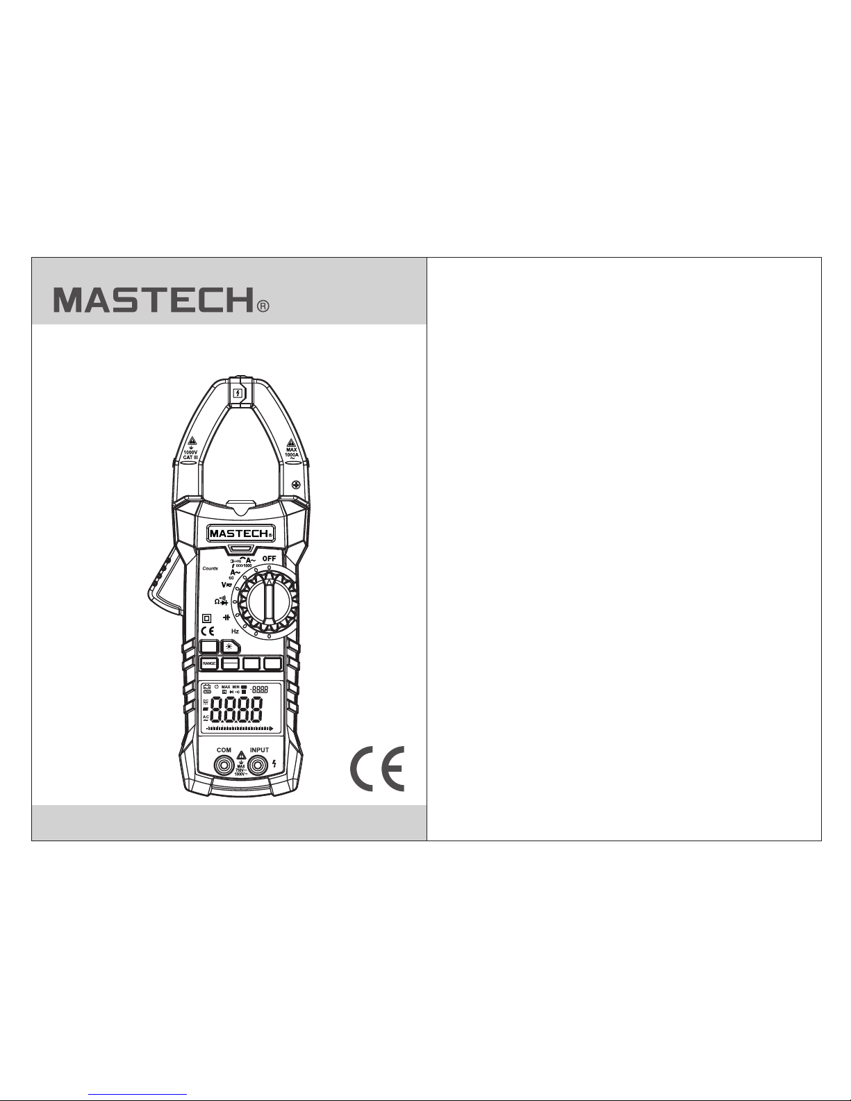
MS2015B
AC Digital Clamp Meter
User Manual
%
kHz
NCV°F
mVA°C
nµmF
MKΩHz
INR
0 10 20 30 40 50 60 66
Z
REL
Temp
NVC
6600
FUNC
MAX
MIN
REL
HOLD
MS2015B AC CLAMP METER
Page 2

CONTENTS CONTENTS
1. Safety Information.............................1
1.1 Preliminary...............................................1
1.2 Usage ......................................................1
1.3 Symbols...................................................3
1.4 Maintenance...........................................3
2. Description........................................4
2.1 Part Name................................................5
2.2 Switch, Button and
Input Jack Description..........................7
2.3 LCD Display.............................................7
3. Specifications...................................9
3.1 General ...................................................9
3.2 Technical Indicators................................10
4. Operating Guidance........................13
4.1 Reading Hold.........................................13
4.2 Relative Measurement............................13
4.3 Manual Measuring Range Choice............14
4.4 Function Switch.....................................14
4.5 Back light and
Clamp Head light...................................14
4.6 Automatic Power-Off.................................15
4.7 Measurement Preparation........................16
4.8 Current Measurement ..............................16
4.9 AC voltage Measurement..........................17
4.10 DC Voltage Measurement........................18
4.11 Measure Frequency................................19
4.12 Resistance Test.....................................19
4.13 Diode Test.............................................20
4.14 Circuit Continuity Test.............................20
4.15 Capacitance Measurement.....................21
4.16 Temperature Measurement.....................21
5. Maintenance......................................22
5.1 Replace Battery.........................................22
5.2 Replace Probe..........................................22
6. Accessries..........................................22
Page 3
01 02
1. Safety Information
The me ter mee ts GB/T 139 78-92 d igital multimeter
general tec hnolo gy cond ition s, GB4793.1-19 95
(IEC -6101 0-1, IE C-610 10-2-032) electroni c
measureme nt inst rumen t safety requirements w ith
seco ndary p ollut ion and o ver-voltage standar d
CATll 100 0V.
Please foll ow the sa fety op eration guidelines to e nsure
the sa fe use
The me ter wil l provi de sati sfactory service to you i f you
use and prote ct it app ropri ately.
1.1 Preparation
1.1. 1 When us ing the m eter, th e user should comply with
stan dard sa fety ru les:
- Gene ral sho ck prot ectio n
- Prev ent mis using t he meter
Afte r recei ving th e meter, p lease check for
dama ge that m ay have o ccurr ed during the transport .
1.1. 3 If the me ter has b een sto red and shipped under
hard c ondit ions, p lease c heck and confirm
whet her or no t the met er is damaged.
1.1. 2
1.2 Usage
1.2. 1 When us ing, se lect th e right function and
meas uring r ange.
1.2. 2 Don't e xceed ing ind icated values in each
meas uring r ange.
1.2. 3 When me asuri ng circ uits with the meter
conn ected , do not to uch the p robe tip (metal pa rt).
Warning
Plea se part icula rly note that inap propr iate
use ma y cause s hock or d amage to the meter.
In use , users s hould c omply with commo n
safe ty proc edure s and completely follow t he
safe ty meas ures st ated in the operation man ual.
In ord er to mak e full us e of the meter's
func tions a nd ensu re safe operatio n, plea se
care fully r ead and f ollow the proced ures in t he
oper ation m anual .
1.1. 4 Probe s hould b e in good c ondition. Before use,
plea se chec k wheth er the pr obe insulation is
dama ged, an d wheth er meta l wire is bare.
1.1. 5 Use the p robe ta ble pro vided with the meter to
ensu re safe ty. If neces sary, be replaced with
anot her ide ntica l probe o r one with the same
spec ifica tion.
1.2. 4 When me asuri ng, if th e voltage to be measured is
more t han 60 V DC o r 30 V AC (RMS ), alwa ys keep
your f inger s behin d the fin ger protection device .
1.2. 5 Do not me asure b etwee n measuring end and
grou nd that i s more th an 600 V.
1.2. 6 For man ual mea surin g range, when the value to
be mea sured i s unkno wn in adv ance, choose the
high est mea surin g range f irst and then lower
rang es in seq uence u ntil th e correct range is found.
1.2. 7 Befor e rotat ing sel ector switch to change
meas uring f uncti on, rem ove the probe from the
circ uit to be m easur ed.
1.2. 8 Don't m easur e resis tors, capacitors, dio des and
circ uits co nnect ws to pow er.
1.2. 9 Durin g the tes t of curr ent, resistors, capac itors ,
diod es and ci rcuit c onnec tions, be careful to avoi d
conn ectin g the met er with the voltage source.
1.2. 10 Do not m easur e capac itance before capacit or is
disc harge d compl etely.
Page 4

03 04
1.3 Symbols
Note ( Impor tant sa fety information. Ref er to
the op erati on manu al)
Doub le insu latio n protection (class II)
CAT III Acco rding t o pulse v oltage tolerance
prot ectio n level p rovided by IEC 61010-1
stan dard ov ervol tage (installation) l evel II I and
poll ution d egree 2 .
The mete r compl ies wit h EU standard
Grou nding
1.4 Maintenance
1.4. 1 Don't t ry to ope n the met er bottom case to adjust
or rep air. Suc h opera tions c an only be performed
by tec hnici ans who f ully un derstand the meter
and el ectri cal sho ck haza rd.
1.4. 2 Befor e openi ng the me ter bottom case or batter y
cove r, remov e probe f rom the c ircuit to
be mea sured .
2. Description
- The mete r is a port able, p rofes sional measuring
inst rumen t with LC D displ ay and back light for easy
read ing by us ers. Me asuri ng range switch is operat ed
by sin gle han d for eas y opera tion with overload
prot ectio n and low b atter y indicator. It is an ideal
mult ifunc tion me ter for p rofessionals, facto ries,
scho ols, fa ns and fa mily us e.
- The mete r is used t o measu re AC curr ent, AC voltage,
DC vol tage, f reque ncy, duty ra tio, resistanc e,
capa citan ce meas ureme nt, temperature, NCV an d
circ uit con necti on, and t o make diode tests.
- The mete r has an au to meas uring r ange function.
- The mete r has a tes t data du al disp lay function.
- The mete r has a rea ding ho ld func tion.
- The mete r has a rel ative t est fun ction.
- The mete r has max . and min . displ ay function.
- The mete r has a man ual mea surin g range selection
func tion.
- The mete r has a bac k light f uncti on.
- The mete r has a aut o power -off func tion.
1.4. 4 Clean t he mete r with da mp cloth and mild
dete rgent . Do not us e abras ives or solvents.
1.4. 5 Power o ff t he mete r when th e meter is not used.
Swit ch the me asuri ng rang e to OFF position.
1.4. 6 If the me ter is no t used fo r long time, remove the
batt ery to pr event t he meter being damaged.
1.2. 11 Do n ot use th e meter i n explo sive gas, vapor or
dust y envir onmen t.
1.2. 12 If you f ind any a bnorm al phenomena or failure
on the m eter, st op usin g it immediately.
1.2. 13 The mete r shoul d not be us ed unless the bottom
case a nd the ba ttery c over are completely
fast ened in t heir or igina l places.
1.2. 14 Don' t store o r use the m eter in direct sunlight ,
high t emper ature o r high hu midity.
1.4. 3 To avo id wron g readi ngs cau sing electric shock,
when “ ”appe ars on th e meter display,
repl ace the b atter y immed iately.
Dangerous e lectr ic cond uctor.
Page 5

05 06
(1) Cu rrent c lamp he ad
(2) Cl amp hea d light
(3) Pa nel
(4) Tri gger
(5) Ba cklig ht key
(6) Fu nctio n choic e butto n (FUNC)
(7) Ma ximum /mini mum cho ice button
(8) LC D displ ay
(9) Co mmon en d jack
2.1 Part Name
(10) Input ja ck
(11) Rela tive me asure ment bu tton (REL)
(12) Readin g hold (H OLD)
(13) Transfe r switc h
(14) NCV indi cator
1
4
9
11
13
14
12
10
8
7
6
5
3
2
%
kHz
NCV°F
mVA°C
nµmF
MKΩHz
INR
0 10 20 30 40 50 60 66
Z
REL
Temp
NVC
6600
FUNC
MAX
MIN
REL
HOLD
MS2015B AC CLAMP METER
Page 6

07 08
2.3 LCD Display
2.2 Switch, Button And Input Jack Description
FUNC b utton : used fo r measu ring function switch.
butt on: use d for bac kligh t control.
RANGE butto n: used f or swit ching between automat ic
measuring r ange an d manua l measu ring range.
MAX/ MIN but ton: us ed for ma ximum/minimum displ ay
func tion.
REL bu tton: u sed for s witch t o enter relative
measureme nt stat e.
HOLD b utton : used fo r readi ng hold.
OFF po sitio n: used f or shut ting off the power.
INPU T jack: v oltag e, resi stance, frequency,
temp eratu re, cap acita nce, diode, circuit con necti on
input wire co nnect ing ter minal.
COM ja ck: vol tage, r esist ance, frequency, te mpera ture,
capacitan ce, dio de, cir cuit connection commo n wire
connectin g termi nal.
Transfer swi tch: us ed for se lecting function and
measuring r ange.
Clam p head: u sed for c urren t measurement.
H
AC Alte rnati ng Curr ent
Buzz er cont inuit y
Auto matic m easur ing ran ge mode
Maximum measurement state
Minimum measurement state
Relative measurement mode
Automatic power-off state
Low Battery
Reading hold state
Percentage (duty ratio)
Millivolt, Volt (voltage)
Amperes (Current)
Nano farad, Microfarad, Millifarad
Ohm, Kilohm, Megohm (resistance)
Hertz, Kilohertz, Megahertz (frequency)
Hz,kHz,MHz
Ω,kΩ,MΩ
nF,μF,
mV,V
%
AUTO
MAX
MIN
REL
A
DC Dire ct Curr ent
Diode
%
kHz
NCV°F
mVA°C
nµmF
MKΩHz
INR
0 10 20 30 40 50 60 66
Z
REL
Page 7

09 10
3. Specifications
3.1. 1 Auto mea surin g range .
3.1. 2 Full me asuri ng rang e overload protection
3.1. 3 Th e maxim um allo wable v oltage between
meas ureme nt end an d groun d: 1000V DC or
750 AC ( no R MS)
3.1. 4 Opera tiona l heigh t: maximum 2000 m
3.1. 5 Displ ay: LCD
3.1. 6 Displ ayed ma ximum v alue: digit 6600.
3.1. 7 Polar ity ind icati on: automatic indicat ion,
'-' me ans neg ative p olari ty.
3.1. 8 Excee ding me asuri ng range display: '0L' or ' -0L'
3.1. 9 Sampl ing rat e: abou t 3 times/sec., simulat ion
bar: 3 0 times /sec.
3.1. 10 Unit d ispla y: has fu nction and power unit dis play.
3.1. 11 Aut o off time: 1 5 mins
3.1. 12 Oper ating p ower su pply: 9V battery.
3.1. 13 Batt ery und ervol tage indication: LCD
disp lays sy mbol .
3.1. 14 Temperature coeffic ient: l ess tha n
0.1× accur acy/° C
3.1. 15 Oper ation al temp erature: 18°C ~28°C
3.1. 16 Stor age tem perat ure: -10°C ~ 50°C
3.1. 17 Dime nsion : 225×8 6×33mm
3.1. 18 Weight : about 3 20g (in clude battery)
The me ter sho uld be re calib rated under the conditi on
of 18° C~28° C, rela tive hu midity less than 75% .
3.1 General
3.2 Tec hni cal I ndi cat ors
Envi ronme nt temp eratu re: 23±5°C, relative hu midit y
(RH):<75%
3.2. 2 AC Cur rent
Accura cy
Resolu ti on
Measur in g
±(2.5% of reading+6 digits)
66A
660A
1000A
0.01 A
0.1A
1A
- Maxi mum inp ut curr ent: 10 00A AC
- Freq uency r ange: 4 0 ~ 100Hz
Tempera ture
Freq uency r ange: - 20°C~10 00°C
Accuracy
Resolution
Measuring range
±(2% of reading+2 digits)
1000°C
1°C
3.2. 3 DC volt age
Accura cy
Resolu ti on
Measuring range
±(0.7% of reading+2 digits)
660.0mV
6.60 0V
66.0 0V
0.1m V
0.00 1V
0.01 V
660.0V
1000V
0.1V
1V
±(0.8% of reading+2 digits)
±(0.8% of reading+2 digits)
- Inpu t imped ance: 1 0MΩ
- Maxi mum inp ut volt age: 10 00V DC
Page 8

Function Resolution
Measuring range
- Forw ard DC cu rrent i s about 1 mA
- Back ward DC v oltag e is abou t 3.3V
- Over load pr otect ion: 25 0V DC or AC (RMS)
0.00 1V
Display app roxim ate dio de
forw ard vol tage va lue
Accuracy
Resolution
Measuring range
±(0.8% of reading + 3 digits)
±(1.2% of reading + 3 digits)
66.0 0MΩ
660.0Ω
6.60 0kΩ
66.0 0kΩ
660.0kΩ
6.60 0MΩ
0.00 1kΩ
0.1Ω
0.01 kΩ
0.1k Ω
0.00 1MΩ
0.1M Ω
Accuracy
Resolution
Measuring range
0.00 1Hz66.0 0Hz
660.0Hz 0.01 Hz
0.01 kHz66.0 0kHz
±(0.5% of reading + 2 digits)
0.00 1kHz
6.60 0kHz
660.0kHz
6.60 0MHz
66.0 0MHz
0.1k Hz
0.00 1MHz
0.01 MHz
11 12
Note :
In the s mall vo ltage m easur ing range, when the probe
is not c onnec ted wit h the cir cuit to be tested, and the
mete r may hav e fluct uatin g readings, which is norm al
and ca used by t he mete r's hig h sensitivity. When the
mete r is conn ected w ith the c ircuit to be tested, you wi ll
get ac tual me asure d value .
3.2. 4 AC Voltag e
Accuracy
Resolution
Measuring range
±(1.0% of reading + 4 digits)
±(0.8% of reading + 3 digits)
1V
0.1V
0.01 V
0.00 1V6.60 0V
66.0 0V
660.0V
750V
- Inpu t imped ance: 1 0MΩ
- Maxi mum inp ut volt age: 75 0V AC
- Freq uency r ange: 4 0 ~ 400Hz
Note :
In the s mall vo ltage m easur ing range, when the probe
is not c onnec ted wit h the cir cuit to be tested, and the
mete r may hav e fluct uatin g readings, which is norm al
and ca used by t he mete r's hig h sensitivity. When the
mete r is conn ected w ith the c ircuit to be tested, you wi ll
get ac tual me asure d value .
3.2.5 Frequ ency
3.2.6 Resis tance
- Open c ircui t volta ge: abo ut 0.4V
- Over load pr otect ion: 25 0V DC or AC (RMS)
3.2.7 Diode t est
Page 9

13 14
Accuracy
Resolution
Measuring range
3.2. 8 Circu it Cont inuity Test
- Over load pr otect ion: 25 0V DC or AC (RMS)
0.1Ω
If the r esist ance of c ircui t to
be measured i s less th an
30Ω, t he mete r's bui lt-in
buzzer may so und.
3.2. 9 Capac itanc e
Accuracy
Resolution
Measuring range
±(4.0% of reading + 5 digits)
6.60 0nF
- Over load pr otect ion: 25 0V DC or AC (RMS)
66.0 0nF
660.0nF
6.60 0µF
66.0 0µF
660.0µF
6.60 0mF
66.0 0mF
0.00 1nF
0.01 nF
0.1n F
0.00 1µF
0.01 µF
0.1µ F
0.00 1mF
0.01 mF
4.1. 1 In the pr ocess o f measu rement, if reading hold i s
requ ired, p ress “H OLD” ke y, the value on the
disp lay wil l be lock ed.
4.1. 2 Press t he “HOL D” key ag ain to cancel reading hol d.
4. Operating Guidance
4.1 Reading Hold
4.2 Re lativ e measu remen t
4.2. 1 Relat ive mea surem ent only can be used to
meas ure cur rent, v oltag e, resistance, c apaci tance
and te mpera ture.
4.2. 2 Press t he “REL ” key to en ter relative
meas ureme nt mode . Th e automatic measuring
rang e will be d isabl ed. Pre ss “REL” key again to
rest ore aut omati c measu ring range.
Note : When me asuri ng, to us e relative measuremen t,
input corre spond ing mea suring range first thro ugh
the pr obe.
4.3 Manual measuring range choice
Use RANGE key t o selec t autom atic or manual
measuring r ange. The p reset s election is automatic
measuring r ange.
Pres s to swit ch to man ual mea suring range. In the
manual meas uring r ange mo de, click once to change to
a higher grad e, and cl ick aga in to change to the top grade .
Continue to p ress th is key to c hange to the bottom grade .
If thi s key is pr essed m ore tha n 2 seconfs, the meter
will switch b ack to th e autom atic measuring range.
4.4 Function switch
4.4. 1 In the DC c urren t measu rement state, press the
“FUN C” key, and th e meter w ill enter AC current
meas ureme nt stat e. Presses “FUNC” key aga in,
and th e meter w ill ent er DC cur rent measurement
stat e again .
4.4. 2 In the re sista nce gra de, press the "FUNC" butt on
to swi tch amo ng resi stanc e, diode and
cont inuit y detec tion.
Page 10

15
4.5. 1 In the pr ocess o f measu rement, if ambient ligh t
is too d ark to re ad, pre ss “ ”key to turn on the
back light . Th e backl ight wi ll automatically turn o ff
afte r about 3 0 secon ds.
4.5. 2 Durin g this pe riod, p ressing “ ”key will turn off
back light .
4.5. 3 In the cu rrent g rade, t he meter will turn on
back light a nd clam p head li ght.
Back light i s LED wit h high wo rking current.
If bac kligh t is used o ften, it will shorten bat tery
life , so use ba cklig ht only w hen necessary.
Note : When ba ttery v oltag e <7V, LC D displays “ ”
(low voltag e) symb ol. But w hen using the backlight ,
the ba ttery v oltag e will dr op due to the high working
curr ent and t he“ ”sy mbol ma y display. (When the
“ ”sym bol sho ws, acc uracy o f measurement is not
guarantee d). At thi s time, d on't replace the batter y.
Continue to u se the me ter nor mally without using the
backlight , and rep lace th e battery only when the “ ”
symb ol show s under n ormal u se.
_
4.6 Automatic power-off
4.6. 1 If ther e is no ope ratio n during any 15 minute
peri od afte r turni ng the ma chine on, the mete r
will e nter a su spend ed stat e and automatically
powe r off to save t he batt ery. Within 1 minute
befo re shut down, t he buzz er will sound 3 times.
Imme diate lyt bef ore shu tting down, the bu zzer
will m ake a lon g sound .
4.6. 2 After au tomat ic powe r-off, press the “FU NC” key
to res tore th e meter t o normal function.
4.6. 3 Holdi ng any ot her key e xcept “FUNC” key and
“HOL D” more t han 2 sec onds wh en powering on
will c ancel t he auto matic p ower-off functio n.
4.7 Measurement preparation
4.7.1 Turn the t ransf er swit ch to turn on the power.
When b atter y volta ge is low ( about <7V), LCD
disp lays “ ”s ymbol . Replace the battery
imme diate ly.
4.7.2 “ ”symb ol mean s that in put voltage or current
shou ld not be m ore tha n the ind icated value. This
is to pr otect t he inte rnal li ne from damage.
4.7.3 Place t ransf er swit ch to the required measur ing
func tion an d range .
4.7.4 When co nnect ing lin e, please connect the
comm on test l ine fir st, then connect charge d test
line . When re movin g line, r emove charged test
line f irst.
_
4.8 Current Measurement
Elec tric sh ock haz ard.
Remove the pr obe fro m the met er before
measuring w ith cur rent cl amp.
Warning
4.8.1 Place m easur ing swi tch in position . At this
time , the met er is in th e AC current measurement
stat e.
4.8.2 Hold th e trigg er, open c lamp head, and clip one
lead o f measu remen t circu it to be tested in the
clam p.
4.8.3 LCD wil l show re ading s.
Note :
1) Clamping t wo or mor e leads o f circuit to be tested
simu ltane ously w ill giv e invalid readings.
2) To get accu rate re ading s, plac e the lead to be tested
at the c enter o f curre nt clam p.
3)“ ” in dicat es that m aximu m input AC current is
1000 A and DC cur rent 10 00A.
A~
16
4.5 Back light and clamp head light
Page 11

17 18
4.9 AC voltage measurement
Elec tric sh ock haz ard.
Pay special a ttent ion to av oid shock when
measuring h igh vol tage.
Don' t input v oltag e more than AC600V RMS.
Warning
4.9. 1 Inser t black p robe to t he COM jack and insert red
prob e to the IN PUT jac k.
4.9. 2 Place t ransf er swit ch to AC voltage position.
Pres s the “FU NC” key t o select AC voltage
meas ureme nt stat e.
4.9. 3 Conne ct the pr obe wit h voltage source or both
ends o f load in p arall el for me asurement.
4.9. 4 LCD wil l show re ading s..
V
Note :
1). In t he smal l volta ge meas uring range, the probe is
not co nnect ed with t he circ uit to be tested, an d the
mete r may hav e fluct uatin g readings, which is norm al
and ca used by t he mete r's hig h sensitivity. When t he
mete r is conn ected w ith the c ircuit to be teste d, you
will g et actu al meas ured va lue.
2). In t he rela tive me asure ment mode, the automati c
meas uring r ange is d isabl ed.
3) “ ”me ans tha t maxim um inpu t voltage is 750V AC.
Elec tric sh ock haz ard.
Pay special a ttent ion to av oid shock when
measuring h igh vol tage.
Don' t input v oltag e more than DC1000V RMS.
Warning
4.10 .1 Inse rt blac k probe t o the COM jack and insert
red pr obe to th e INPUT jac k.
4.10 .2 Plac e trans fer swi tch to AC voltage position .
Pres s the “FU NC” key t o select AC voltage
meas ureme nt stat e.
4.10 .3 Conn ect the p robe wi th voltage source or both
ends o f load in p arall el for me asurement.
4.10 .4 LCD wi ll show r eadin gs. Polarity indicati on
show s the loa d conne cted wi th the red probe.
V
Note :
1) In th e small v oltag e measu ring range, the probe is
not co nnect ed with t he circ uit to be tested, and the
mete r may hav e fluct uatin g readings, which is norm al
and ca used by t he mete r's hig h sensitivity. When t he
mete r is conn ected w ith the c ircuit to be teste d, you
will g et actu al meas ured va lue.
2) In th e manua l measu ring ra nge mode, the LCD only
show s “OL” or “ -OL”, w hich in dicates overrange.
Choo se a high er meas uring r ange.
3) “ ”me ans tha t maxim um inpu t voltage is 1000V DC.
4.10 DC voltage measurement
Page 12

19 2 0
4.11.3. 1 Inser t black p robe to the COM jack and inse rt
red pr obe to th e INPUT j ack.
4.11.3. 2 Place t ransf er swit ch in position “HZ”.
4.11.3. 3 Conne ct the pr obe wit h signal or both ends of
load i n paral lel for m easur ement.
4.11.3. 4 LCD wil l show re ading s..
4.12 Resistance test
Elec tric sh ock haz ard.
When m easur ing cir cuit im pedance, deter mine
that t he powe r suppl y is disconnected and the
capa citor i n the cir cuit is c ompletely disc harge d.
Warning
4.12 .1 Inse rt blac k probe t o the COM jack and insert red
prob e to the IN PUT jac k.
4.12 .2 Plac e measu ring ra nge switch in Ω position.
The mete r is in the m easur ement state.
4.12 .3 Conn ect the p robe to t he both ends of resistor or
circ uit to be t ested f or measurement.
4.12 .4 LCD wi ll show r eadin gs.
Note :
1) Whe n the inp ut end is o pen, LC D shows “0L”
out- of-ra nge con ditio n.
2) Whe n the res istan ce to be te sted > 1MΩ, the meter
read ing wil l stabi lize af ter a few seconds, which is
norm al for hi gh resi stanc e readings
4.13 .4 Conn ect the r ed prob e to diode anode and
conn ect the b lack pr obe to di ode cathode to
make t est.
4.13 .5 LCD wi ll show r eadin gs.
Note :
1) Wha t the met er show s is an app roximation of diode
forw ard vol tage dr op.
2) If th e probe h as reve rse con nection or the probe is
open , the LCD w ill sho w “0L”
4.14 Circuit continuity test
Elec tric sh ock haz ard.
When m easur ing cir cuit co ntinuity, determi ne
that t he powe r suppl y is disconnected and the
capa citor i n the cir cuit is c ompletely disc harge d.
Warning
4.14 .1 Inse rt blac k probe t o the COM jack, insert red
prob e to the IN PUT jack.
4.14 .2 Plac e measu ring sw itch in positionΩ .
4.14 .3 Pres s the “FU NC” key t o switch to circui t
cont inuit y measu ring state.
4.14 .4 Conn ect the p robe to t he both ends of circuit to
be tes ted for m easur ement.
4.14 .5 If the r esist ance of c ircuit to be measured is le ss
than 4 0Ω , the me ter's b uilt-in buzzer may soun d.
4.14 .6 LCD wi ll show r eadin gs.
4.11 Measure frequency
Elec tric sh ock haz ard.
Pay special a ttent ion to av oid shock when
measuring h igh vol tage. Don't input volta ge
more t han AC 2 50V RMS .
Warning
4.13 Diode Test
4.13 .1 Inse rt blac k probe t o the COM jack and insert
red pr obe to th e INPUT jac k.
4.13 .2 Plac e measu ring sw itch in positionΩ .
4.13 .3 Pres s the “FU NC” key t o switch to measur ing
stat e.
Page 13

21 2 2
Elec tric sh ock haz ard.
To avoid el ectri c shock , before measuring
capa citan ce, dis charg e capacitance complet ely.
Warning
4.15 .1 Inse rt blac k probe t o the COM jack, insert red
prob e to the IN PUT jac k.
4.15 .2 Plac e measu ring sw itch in position .
4.15 .3 After d ischa rging c apacitor completely, con nect
the pr obe to th e ends of c apacitor to be tested.
4.15 .5 LCD wi ll show r eadin gs.
Note :
1) Whe n measu ring bu lk capa citor, stable readings
will t ake som e time.
4.16 Tempe rature Measurement
4.16 .1 Inse rt the te mpera ture probe into the COM,
INPU T jack.
4.16 .2 Plac e measu ring sw itch in position Temp.
4.16 .3 LCD wi ll show r eadin gs.
5. Maintenance
5.1 Replace battery
Before open ing the m eter ba ttery cover, the probe
shou ld be rem ove d fro m the cir cuit to be
measured to a void el ectri c shock.
Warning
5.1. 1 When th e batte ry indi cator “ ”appears, repla ce
the ba ttery i mmedi ately.
5.1. 2 Unscr ew the fa steni ng screw of the meter batte ry
cove r and rem ove it.
5.1. 3 Repla ce the ba ttery.
Note : Do not re verse t he batt ery polarity.
5.2 Replace probe
When r eplac ing the p robe, be replaced with
anot her ide ntica l probe or one with the same
leve l. The pr obe sho uld be in good condi tion,
prob e level : 1000V, 10A.
Warning
If the p robe is d amage d, such a s bare metal wire,
replace the p robe.
6. Accessories
1) Pro be Leve l: 1000 V 10A One pair
2) Use r Manua l 1 pc
3) Bat tery 9V 1 pc
HYS007028
Note :
If the p robe is o pen or ci rcuit s resistance to be tested i s
more t han 400 Ω , the dis play wi ll show “0L”.
4.15 Capacitance measurement
 Loading...