

Page 1

AC Leakage Current Clamp Meter
Instruction Manual
Contents
1. Safety information
1-1.Safety precaution
1-2. Symbols
2. Meter illustration
2-1. Panel description
2-2. LCD display
3. Specification
3-1. General feature
3-2 Electric specification
4. Operating instruction
4-1 LPF using
4-2 Data HOLD
4-3 Range Switching
4-4 Function selection
4-5 Maxim value
4-6 Back Light
4-7 Sleep Mode
5. Measurement operating
5-1. AC Current measurement
5-2. Leakage current measurement
5-3. DC /AC Voltage measurement
5-4. Frequency & Duty cycle measurement
5-5. Resistance measurement
5-6. Diode check
Page 2

5-7. Continuity check
- 3 -
5-8 .Capacitance measurement
5-8. Temperature measurement
6. Maintenance
6-1 Battery replace
6-2 Fuse replace
6-3. Cleaning and Decontamination
1. Safety information
The meter is a handheld and battery operated Digital AC Clamp
Meter with multi function. This clamp meter has been designed to
meet IEC1010-1 and CAT III over Voltage category.
Warning
To avoid possible electric shock or personal injury and possible damage
to the meter or the equipment under test, you are must be adhere to the
following rules.
1-1. Safety cautions
● User must be read the operating instructions thoroughly and
completely before operating your meter. Pay particular attention
to WARNING, which will inform you of potentially dangerous
procedures.
● Do not apply more than the rated voltage ,of marked on the meter,
between
the “INPUT” terminal and “COM” terminal.
● Do not expose the instrument to direct su
nlight, extreme
temperature and moisture
or dew full.
● You always are careful when working with voltage above
60V DC or 30V AC rms.
● Keep fingers behind the clamp barrier while measuring
current..
- 4 -
●
Always inspect the test lead for damaged insulation or exposed
metal.
1-2. Symbols
Note international Electrical Symbol.
Dangerous Voltage
Ground
AC (Alternating
current)
Warning see
explain in manual
DC (Direct
Current)
Double insulation
2. Meter illustration
Page 3
39 99
11
12
13
10
7
4
2
3
5
6
9
8
1
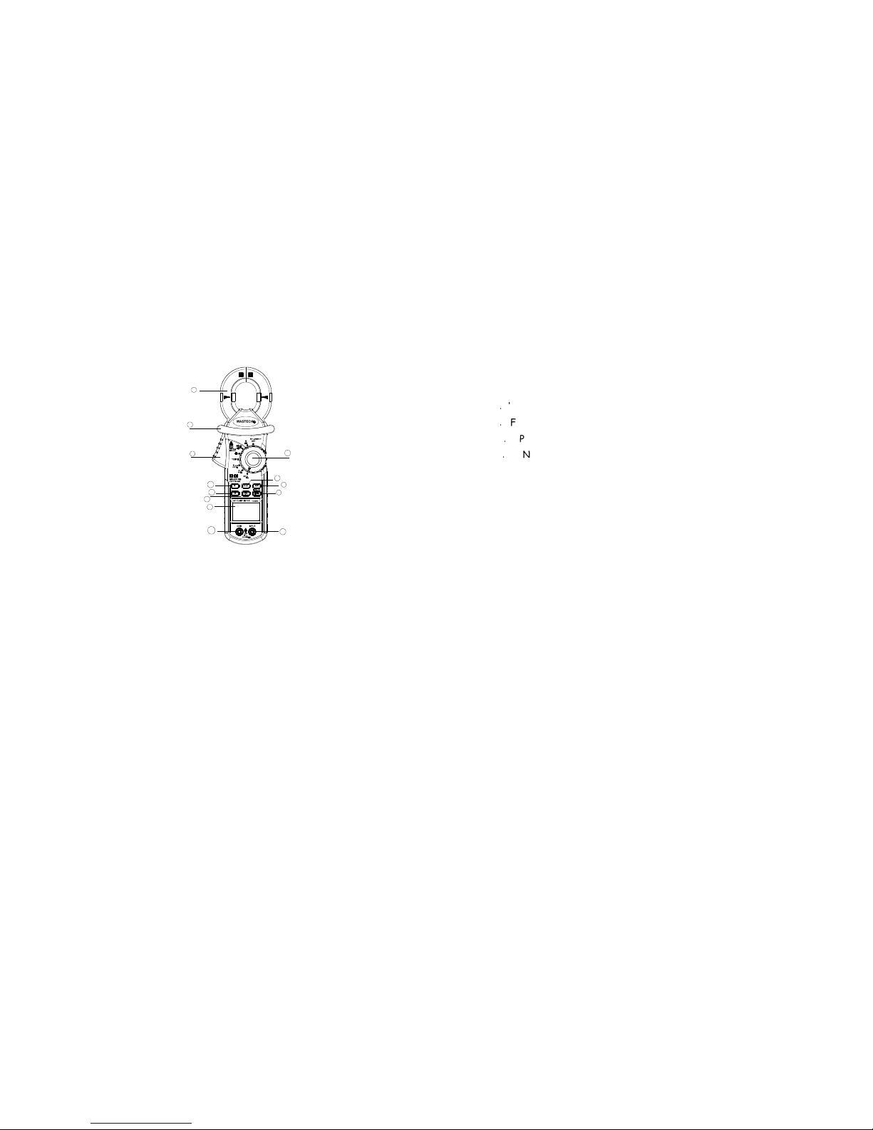
Fig.1 MS2010B Front arrangement
- 5 2-1 Panel description
1. Clamp jaw ; it is as current transformer(CT) when measuring
current flowing through the conductor .
2. Trigger
3. Clamp Barrier:
4. LCD display
5.‘H/ * ’ button : Hold & Back Light
When push this button, the display will keep the last reading.
Once push again, the
Meter will return the normal mode.
6. Knob: it is rotary switch for select function.
7. ‘Hz/%’button: Frequency & Duty cycle mode
8.‘RANGE’ button: Change Auto or Manual mode
9.‘FUNC’ button : Change function mode
10.‘LPF’ button: Used as Low Pass Filter ON/OFF switch.
11. ‘INPUT’ terminal
12. ‘COM’ terminal
13. ‘REL’ push button: Relative measurement mode
- 6 -
2-2. LCD display
Page 4

Alternating current/ voltage
Directive current/voltage
Diode
Buzzer
Auto rangi
ng mode
Relative measurement
Use LPF
No use LPF
Data hold
Low battery indicator
- 7 -
%
Duty cycle
mV,V
Voltage unites
mA,A
Current unites
℃
Temperature unite
nF,µF
Capacitance unite
Ω,kΩ,MΩ
Resistance unites
Hz,kHz
Frequency unites
3. Specification
3-1.General feature
● Auto ranging Digital Clamp Meter. But the meter may select manual Function
mode by ‘RANGE’button.
● 3 1/2 digit(200 count) LCD display
● Over load indication ; ‘OL’symbol will displayed on the LCD.
● Jaw opening capability: 32mm
● Low battery indication : battery symbol is appears on the LCD.
● Auto power OFF: If the meter is idle for more than 15 minutes, the meter
automatically turns the power off.
● Sampling rate: 2times/s
● Power supply: 1.5V battery(AAA type) x 3pcs.
℃ ℃
● Operating temperature & Humidity: 0 to 40 ; < 80% RH
● Storage temperature & Humidity : -10 to 50 ; <70% RH
℃ ℃
● Dimension(L x W x H) & Wight : 260 x 92 x 55mm; Approx. 400g
- 8 3-2.Electrical Specification
[1] AC Current
Range Resolution Accuracy
40mA 0.01mA
(
50 ~ 60Hz) (30~50Hz,
Page 5

400mA 0.1mA
±(1%rdg+8dgt)
60~10KHz)
No available
4A 1mA
40A 10mA
400A 100mA
600A 1A ±(1.5%rdg+3dgt)
[2] AC Voltage
Range Resolution Accuracy
400mV 0.1mV
(
50 ~ 60Hz)
±(0.8%rdg+5dgt)
(30~50Hz,
60~10KHz)
±(2%rdg+10dgt)
4V 1mV
40V 10mV
400V 0.1V
600V 1V
- 9 -
[3] DC Voltage
Range Resolution Accuracy Input impedance
4200mV 0.1mV
4V 1mV
40V 10mV ±(0.7%rdg+3dgt) 10MΩ
400V 0.1V
600V 1V ±(0.8%rdg+5dgt)
[4] Frequency & Duty cycle measurement
The meter is may be measuring the frequency and duty cycle in the AC current
range or AC voltage range by press the ‘Hz/%’ push key.
Frequency range is 1Hz to 2KHz in the current range, and then 1Hz to 100KHz
in the voltage range.
(
4-1)Current measurement range
Range Resolution Accuracy Over load protection
10Hz 0.001Hz ±(2%rdg+5dgt) 250V DC or AC rms
(by PTC protection
circuit)
100Hz 0.01Hz
±(1.5%rdg+5dgt)
1000Hz 0.1Hz
2KHz 1Hz
>2KHz No available
1 to 99% 0.1% ±3%
*** Sensitivity is >AC 10mA(rms)
- 10 -
(4-2) Voltage measurement range
Range Resolution Accuracy Over load protection
10Hz 0.001Hz ±(2%rdg+5dgt) 250V DC or AC rms
(by PTC protection
100Hz 0.01Hz
Page 6

1000Hz 0.1Hz ±(1.5%rdg+5dgt) circuit)
10KHz 1Hz
100KHz 10Hz ±(2%rdg+5dgt)
>100KHz No available
1 to 99% 0.1% ±3%
*** Sensitivity is >AC 0.1V (rms)
[5] Resistance
Range Resolution Accuracy Over load protection
400Ω 0.1Ω
±(1%rdg+2dgt)
250V DC or AC rms
(by PTC protection
circuit)
4KΩ 1Ω
40KΩ 10Ω
400KΩ 0.1KΩ
4MΩ 1KΩ
40MΩ 10KΩ ±(2%rdg+5dgt)
- 11 -
[6] Capacitance measurement
Range Resolution Accuracy Over load
protection
40nF 0.01nF
400nF 0.1nF
±(4%rdg+5dgt
)
250V DC or AC rms
(by PTC protection
circuit)
4uF 1nF
40uF 0.01uF
100 uF 0.1 uF
[
7] Temperature
Range Resolution Accuracy
-20 ℃to
1000℃
1℃ -20℃ to 0℃ :±(5.0%rdg+5dgt)
0 ℃to 400 ℃ :±(1.0%rdg+3dgt)
400℃ to 1000℃ :±(2.0%rdg+3dgt)
[6] Diode check
Test current : 1mA.
[7] Continuity
If the resistance under testing circuit less than 70Ω, buzzer will sound.
Open circuit voltage: 1.2V.
4. Operating instruction
4-1 LPF usage
The meter have Low- Pass-Filter to reduce the influence of high frequency
noise above 1KHz(3db). This LPF feature is available in all AC Voltage or AC
Current measurement mode.
- 12 -
The ‘LPF’ button is act as ON/OFF switch for LPF circuit connection. When
LPF is activated,
Most of noise above 1KHz will decay greatly. So we can obtain more stable and
Page 7

accurate readings on low frequency response.
4-2. Data HOLD
The push key is used to maintain the measurement data unchanging.
Press ‘HOLD” push key to inter and exit the hold mode in any mode. That act
with trigger. The meter will resume the normal measurement mode by
pressing the key again.
4-3 Range switching
“RANGE” button is the auto/manual measurement push key that act with
trigger. The default is auto measurement when power on. Press this key once,
will switch to manual measurement mode, and then press once again, will
switch to auto measurement mode.
4-4. Function switching
“FUNC” key is used as the function selection key that acts with trigger. Use
the key as switch of DC/AC, Diode/ Continuity and / .
℃ ℃
4-5. Maximum value hold
“MAX” key is act with trigger. Press this key once, the maximum value is
holding will Displays ‘MAX’ symbol on the LCD), and the press once again, will
switch to normal Measurement mode.
After pressing the key, A/D will keep working, and the display value
are
always up dated and keep the maximum value.
- 13 -
4-6. Back Light
“ ”Push key is used control Black Light. When press this key and held more
than 2sec, will enable Back Light for 15secs. Press the key again within
15secs, back light will disable.
4-7. Sleep mode (Auto power OFF)
If the meter is idle for more than 15minutes, the meter automatically turns
the power off.
In this sleep mode, the meter is save battery energy.
In the sleep mode, the meter may be turns normal operating mode by
“RANGE”,“MAX”,“ ”Key and rotary switch.
There are two ways to disable the sleep mode as following:
(1) In the auto power off state , you are pushing “HOLD” key.
(2) Push and held “HOLD” key, turn on power by rotary switch at the same
time.
5. Measurement operating
5-1. AC Current measurement
1.Set the rotary switch to the desired “A~” position.
2. Press the clamp trigger to open jaw and clamp a conductor in that flowed
measured current, making sure that the jaw is firmly closed around the
conductor.
3. Set the conductor in that flow the measured current to centre position of
jaw as far as
Possible. In this time, measurement accuracy is best.
4. Read current value on the LCD display.
- 14-
Not:(1)Use the Low Pass Filter by pushing “LPF” button if necessary.
(2)
When measurement the current of transmission line, must be clamp
Page 8

one line only between the two transmission ine .
5-2. Leakage current measurement
This meter can measure the leakage current on the one-phase or three-phase
circuit equipment as well as the conductor in that flow the leakage current.
1. Set the rotary switch to the 20mA~ range.
2. Clamp the conductor in that flow the leakage current, and the read the
leakage 0current value on the LCD display.
5-3. DC/AC Voltage measurement
1. Set the rotary switch to the “V” position. The DC mode is default mode.
To switch to
The AC measure mode must be press once time the “FUNC” button.
2. Insert the red test lead in to the ‘INPUT’terminal and the black test
lead into the ‘COM’terminal.
3. Connect the test lead across with the object being measured. The
measured value will be show on the LCD display.
Note:
When DC or AC voltage measurement has been completed,
disconnect the connection
between the test lead and circuit under test.
5-4. Frequency & Duty cycle measurement
To measure the frequency or Duty cycle of induced current
from the
- 15 clamp jaw, done according to following procedure.
1. Set rotary switch to the 40/400mA, 4/.40A or 400A position.
2. Press the clamp trigger to open jaw and clamp a conductor in that
flowed
Measured current, making sure that the jaw is firmly closed around
the conductor.
3. Press the ‘Hz/%’ push key to into the Frequency mode or Duty cycle
mode.
Measured value will be displayed on the LCD.
To measure the frequency or duty cycle of AC voltage that measured in
the “ V” range, one as following:
1. Set rotary switch to the “V” position.
2. Done section 5-4 (2) ~(3) procedure.
5-5. Resistance measurement
1. Set the rotary switch to the ‘Ω ’ position.
2. Insert the red test lead into the ‘INPUT’ terminal and black test lead
into the ‘COM’ terminal.
3. Connect the test lead across with the object being measured. The
measured value will be show on LCD display.
Note:
● The test lead can add 0.1Ω to 0.2Ω of error to resistance
measurement.To obtain precision reading in low-resistance
measurement, that is the range of 200Ω, short the input terminal
with the test lead probe, and then
read out the contact resistance of test lead. After measuring you can
- 16 -
Page 9

subtract the readied contact resistance value from the reading value.
● For high resistance measurement(>10MΩ), it is normal taking several
seconds to obtain stable reading.
●
If The LCD display‘OL’symbol ,it is indicating open circuit for the
tested resistor or the resistance value of resistor is higher than the
maximum range of the meter.
5-6. Diode check
The diode check function used to check diode, transistor and other
semiconductor device.
In the diode testing, the meter sends a current through the
semiconductor junction, and then measure the voltage drop across the
junction. A good silicon junction will drop between 0.5V to 0.8V.
1. Set the rotary switch to the “‘Ω ” position, and then
press the ‘FUNC’
Push key to into diode check mode.
2. Insert the red test lead into the “INPUT” terminal and the black test
lead into the “COM“ terminal.
3. For forward voltage drop reading on any semiconductor component, place
the red test lead on the component anode and place the black test lead
on the component cathode.
The measured forward drop voltage will show on the LCD display.
4. Reverse the test lead and measure the voltage across the diode again.
● If diode is good, the display shows ‘OL’。
- 17 -
● If diode is shorted, the display shows ‘0’(zero)in both direction.
● If display shows ‘OL’ in direction, the diode is open.
5-7. Continuity check
Set the rotary switch to the “‘Ω ” position.
1. Press the “FUNC” push button to switch into continuity check mode.
2. Insert the red test lead to the “INPUT” terminal, and then black test
lead to the “COM” terminal.
3. Connect the test lead across with the object being measured. If the
resistance of a circuit under test is less than 50Ω,the buzzer will
sound.
5-8. Capacitance measurement
Warning:
To avoid damage to the meter or to the equipment under test,
disconnect power and
discharge all high-voltage capacitors before measuring
capacitance.
You can use the DC voltage function to confirm that the capacitor
is discharged.
Capacitance ranges are 50.00nF, 500.0nF, 5.000uF, 50.00uF, 200.0uF.
To measure capacitance, connect the Meter as follows:
1. Set the rotary switch to“ ” position.
2. Insert the Capacitor under test to the “INPUT” terminal and “COM”
terminal.
The measured value will be displayed on the LCD disp
Page 10

- 18 -
5-9. Temperature measurement
Note:
● MS3202 Multi-Function Socket is used as temperature adapter.
● Use K-type thermocouple probe.
1. Set the rotary switch to the “TEMP” position.
2. In this time, LCD will display the environment temperature.
3. Insert the MS3202 temperature adapter to the “INPUT” and “COM”
terminal , and then
Insert the K-type thermocouple probe to the MS3203 temperature
adapter according to
its polarity.
4. To change the temperature physical unite( ℃or ℃ ) , you can press
the ‘FUNC’ push button.
6.
Maintenance
6-1. Replacing the Battery
When meter display low battery indicator(symbol) on the LCD, you must be
replace the battery to maintain normal operation.
(1)
Disconnect and remove all test probes from any live source and
meter.
(2)
Open the battery cover on the bottom case by screwdriver.
(3)
Remove old battery and snap new one into the battery holder.
6-2. Fuse replacement
Replacing the defective fuse should done according to 6-1section
procedure.
6-3. Cleaning and Decontamination
The meter can be cleaned with soft clean cloth to
remove any oil, grease or grim.
Do not use the liquid solvent or detergent.
–END-
 Loading...