

Page 1
Press 2 Sec
MAX
HOLD
FUNC
RANGE
OFF
600 A
600V
MAX 600V
CAT. III
AC CLAMP METER
MS2010A
HIGH SENSITIVE
Autorange
COM INPUT
LPF
°C °F
mVA
%Hz
nμF
kMΩ
AUTO
LPF
DC
AC
HOLD
REL
LPF
2
20
20
200
V
600V CAT. lll
MAX 600A
AUTO-POWER OFF
mA
TEMP
Ω
A
MS2010A
AC Leakage Current Clamp Meter
Instruction Manual
1. Saf ety inf ormat ion
The met er is a han dheld a nd batt ery ope rated D igita l AC Clamp
Meter w ith mul ti func tion. T his cla mp mete r has bee n desig ned to
meet IE C1010 -1 and CAT I II over Vo ltage c atego ry.
1-1.S afety c autio ns
• User mu st be rea d the ope ratin g instr uctio ns thor oughl y and
compl etely b efore o perat ing you r meter. P ay part icula r atten tion
to WARN ING, wh ich wil l infor m you of po tenti ally da ngero us
proce dures .
• Do not ap ply mor e than th e rated v oltag e ,of mar ked on th e meter,
betwe en the “I NPUT” t ermin al and “C OM” ter minal .
• Do not ex pose th e instr ument t o direc t sunli ght, ex treme
tempe ratur e and moi sture o r dew ful l.
• You alwa ys are ca reful w hen wor king wi th volt age abo ve 60V DC
or 30V AC rm s.
• Keep fi ngers b ehind t he clam p barri er whil e measu ring cu rrent ..
• Alway s inspe ct the te st lead f or dama ged ins ulati on or exp osed
metal .
01
02
03
04 05
Warning
To avoid po ssibl e elect ric sho ck or per sonal i njury a nd poss ible
damag e to the me ter or th e equip ment un der tes t, you ar e must
be adhe re to the f ollow ing rul es.
1-2. S ymbol s
Note in terna tiona l Elect rical S ymbol .
Dange rous Vol tage
Groun d
AC
(Alte rnati ng curr ent)
DC (Dir ect Cur rent)
Warni ng see ex plain
in manu al
Doubl e insul ation
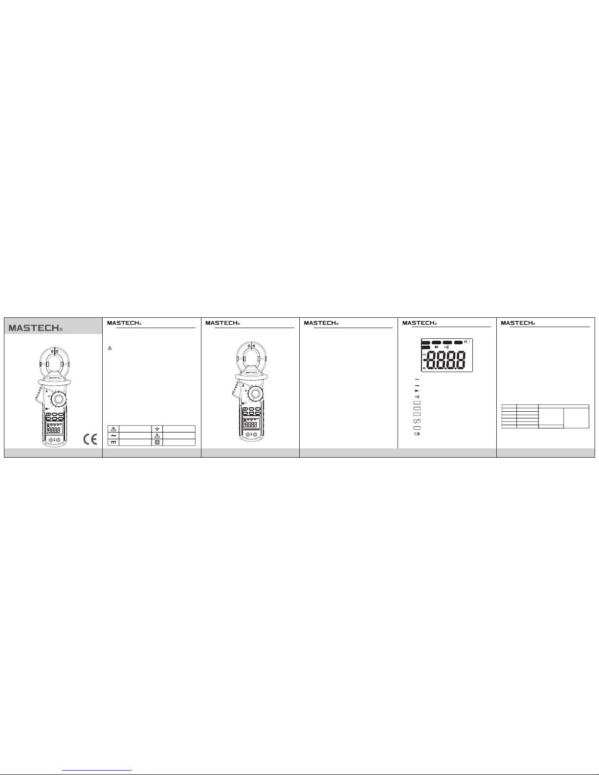
2-1 Pa nel des cript ion
1. Clam p jaw ; it is a s curre nt tran sform er(CT ) when me asuri ng
curre nt flow ing thr ough th e condu ctor .
2. Trigg er
3. Clam p Barri er:
4. LCD di splay
5. “HOL D” butt on
When pu sh this b utton , the dis play wi ll keep t he last r eadin g.
Once pu sh agai n, the Me ter wil l retur n the nor mal mod e.
6. Knob : it is rot ary swi tch for s elect f uncti on.
7. “MAX ” butto n
8. “RAN GE” but ton
9. “FUN C” butt on
10. “LP F” butt on
11. “INP UT” ter minal
12. “CO M” term inal
13. “ * ” Bac k Light p ush but ton
Alter natin g curre nt
Direc tive cu rrent
Diode
Conti nuity
Auto ra nging m ode
Maxim um valu e measu remen t mode
Low pas s filte r is act
Low pas s filte r is non ac t
Data ho ld mode
Low bat tery
2-2. L CD disp lay
• Auto ra nging D igita l Clamp M eter. Bu t the met er may se lect
manua l Funct ion mod e by “RAN GE” but ton.
• 3 1/2 dig it (200 c ount) L CD disp lay
• Over lo ad indi catio n: “OL” s ymbol w ill dis playe d on the LC D.
• Jaw ope ning ca pabil ity: 32 mm
• Low bat tery in dicat ion: ba ttery s ymbol i s appea rs on the L CD.
• Auto po wer OFF : If the me ter is id le for mo re than 1 5 minut es,
the met er auto matic ally tu rns the p ower of f.
• Sampl ing rat e: 2 time s/s
• Power s upply : 1.5V ba ttery ( AAA typ e) x 3pcs .
• Opera ting te mpera ture & Hu midit y: 0°C to 4 0°C; <8 0%
• Stora ge temp eratu re & Humi dity: - 10°C to 5 0°C; <7 0%RH
• Dimen sion (L x W x H ) & Wight : 2 60 x 92 x 55m m; Appr ox. 400 g
3. Spe cific ation
3-1. G enera l featu re
3-2. E lectr ical Sp ecifi catio n
[1] AC Cu rrent
Range
20mA
200mA
2A
20A
200A
Resol ution
0.01m A
0.1mA
1mA
10mA
100mA
Accur acy
(50 ~ 60H z)
±(1%r dg+8d gt)
(30~50Hz,60~10KHz)
±(3%r dg+10 dgt)
600A
1A
AC
DC
AUTO
MAX
LPF
LPF
HOLD
2. Met er illu strat ion
±(1.5 %rdg+ 3dgt)
Press 2 Sec
MAX
HOLD
FUNC
RANGE
OFF
600 A
600V
MAX 600V
CAT. III
AC CLAMP METER
MS2010A
HIGH SENSITIVE
Autorange
COM INPUT
LPF
°C °F
mVA
%Hz
nμF
kMΩ
AUTO
LPF
DC
AC
HOLD
REL
LPF
2
20
20
200
V
600V CAT. lll
MAX 600A
AUTO-POWER OFF
mA
TEMP
Ω
A
°C °F
mVA
%Hz
nμF
kMΩ
AUTO
LPF
DC
AC
HOLD
REL
LPF
Page 2
11
HYS 00677 3
08 09 1006 07
[2] AC Volt age
Range
200mV
2V
20V
200V
Resol ution
0.1mV
1mV
10mV
0.1V
Accur acy
(50 ~ 60H z)
±(0.8 %rdg+ 5dgt)
(30~50Hz,60~10KHz)
±(2%r dg+10 dgt)
600V
1V
• Input i mpeda nce; 10 MΩ
[3] DC Vol tage
Range
200mV
2V
20V
200V
Resol ution
0.1mV
1mV
10mV
0.1V
Accur acy
±(0.7 %rdg+ 3dgt) 10MΩ
600V
1V
Input i mpeda nce
[4] Res istan ce
Range
200Ω
2KΩ
20KΩ
200KΩ
Resol ution
0.1Ω
1Ω
10Ω
0.1KΩ
Accur acy
±(1%r dg+2d gt)
250V DC or AC rms
(by PTC
protection circuit)
2MΩ
1KΩ
Over load protection
20MΩ
10KΩ
±(2%r dg+5d gt)
[5] Temp eratu re
Range
-20°C t o
1000° C
Resol ution
1°C
Accur acy
-20°C t o 0°C
0°C to 40 0°C
400°C t o 1000° C
±(5.0 %rdg+ 5dgt)
±(1.0 %rdg+ 3dgt)
±(2.0 %rdg+ 3dgt)
-4°F to
1832° F
1°F
-4°F to 3 2°F
32°F to 7 52°F
752°F t o 1832° F
±(5.0 %rdg+ 5dgt)
±(1.0 %rdg+ 3dgt)
±(2.0 %rdg+ 3dgt)
[6] Dio de chec k
Test curr ent : 1mA
[7] Con tinui ty
If the re sista nce und er test ing cir cuit le ss than 5 0Ω, buz zer wil l
sound .
4. Ope ratin g instr uctio n
4-1 LP F usage
The met er have L ow- Pas s-Fil ter to re duce th e influ ence of h igh
frequ ency no ise abo ve 1KHz (3db) . This LP F featu re is ava ilabl e
in all AC Vol tage or AC C urren t measu remen t mode.
The “LP F” butt on is act a s ON/OF F switc h for LPF c ircui t
conne ction . When LP F is acti vated , Most of n oise ab ove 1KH z
will de cay gre atly. So w e can obt ain mor e stabl e and acc urate
readi ngs on lo w frequ ency re spons e.
4-2 Da ta HOLD
The pus h key is us ed to mai ntain t he meas ureme nt data
uncha nging .
Press “ HOLD” p ush key t o inter a nd exit t he hold m ode in an y
mode. T hat act w ith tri gger. Th e meter w ill res ume the n ormal
measu remen t mode by p ressi ng the ke y again .
4-3 Ra nge swi tchin g
“RANG E” butt on is the a uto/m anual m easur ement p ush key t hat
act wit h trigg er. The de fault i s auto me asure ment wh en powe r on.
Press t his key o nce, wi ll swit ch to man ual mea surem ent mod e,
and the n press o nce aga in, wil l switc h to auto m easur ement m ode.
4-4 Fu nctio n switc hing
“FUNC ” key is us ed as the f uncti on sele ction k ey that a cts wit h
trigg er. Use th e key as sw itch of D C/AC, D iode/ C ontin uity an d
°C/°F.
4-5 Ma ximum v alue ho ld
“MAX” k ey is act w ith tri gger. Pr ess thi s key onc e, the ma ximum
value i s holdi ng(wi ll Disp lays “M AX” sym bol on th e LCD), a nd the
press o nce aga in, wil l switc h to norm al Meas ureme nt mode .
After p ressi ng the ke y, A/D will k eep wor king, a nd the di splay
value a re alwa ys up dat ed and ke ep the ma ximum v alue.
4-6 Ba ck Ligh t
“ ” Push ke y is used c ontro l Black L ight. W hen pre ss this
key and h eld mor e than 2s ec, wil l enabl e Back Li ght for 1 5secs .
Press t he key ag ain wit hin 15s ecs, ba ck ligh t will di sable .
4-7 Sl eep mod e (Auto p ower OF F)
If the me ter is id le for mo re than 1 5minu tes, th e meter
autom atica lly tur ns the po wer off .
In this s leep mo de, the m eter is s ave bat tery en ergy.
In the sl eep mod e, the me ter may b e turns n ormal o perat ing
mode by “ RANGE ”, “MAX ”, “ ” Key an d rotar y switc h.
There a re two wa ys to dis able th e sleep m ode as fo llowi ng:
(1) In th e auto po wer off s tate , yo u are pus hing “H OLD” ke y.
(2) Pus h and hel d “HOLD ” key, tur n on powe r by rota ry swit ch
at the sa me time .
5. Mea surem ent ope ratin g
5-1 AC Cu rrent m easur ement
1. Set th e rotar y switc h to the de sired “ A~” pos ition .
2. Pres s the cla mp trig ger to op en jaw an d to clam p one con ducto r
only, ma king Su re that t he jaw is f irmly c losed a round t he
condu ctor.
3. Set th e condu ctor in t hat flo w the mea sured c urren t to cent re
posit ion of ja w as far as P ossib le. In th is time , measu remen t
accur acy is be st.
4. Read c urren t value o n the LCD d ispla y.
Not: (1 ) Use the L ow Pass F ilter b y pushi ng “LPF ” butto n if
neces sary.
(2) Whe n measu remen t the cur rent of t ransm issio n line, m ust
be clam p one lin e only be tween t he two li ne .
5-2 Le akage c urren t measu remen t
This me ter can m easur e the lea kage cu rrent o n the one -phas e or
three -phas e circu it equi pment a s well as t he cond uctor i n that fl ow
the lea kage cu rrent .
1. Set th e rotar y switc h to the 20 mA~ ran ge.
2. Clam p the con ducto r in that f low the l eakag e curre nt, and t he
read th e leaka ge 0cur rent va lue on th e LCD dis play.
5-3 DC /AC Volta ge meas ureme nt
1. Set th e rotar y switc h to the “V ” posit ion. Th e DC mode i s defau lt
mode. To sw itch to t he AC meas ure mod e must be p ress on ce
time th e “FUNC ” butto n.
2. Inse rt the re d test le ad in to th e “INPU T” term inal an d the bla ck
test le ad into t he “COM ” termi nal.
3. Conn ect the t est lea d acros s with th e objec t being m easur ed.
The mea sured v alue wi ll be sho w on the LC D displ ay.
Note:
When DC o r AC volta ge meas ureme nt has be en comp leted ,
disco nnect t he conn ectio n betwe en the te st lead a nd circ uit
under t est.
5-4 Re sista nce mea surem ent
1.Set th e rotar y switc h to the “ Ω ” po sitio n.
2.Inse rt the re d test le ad into t he “INP UT” ter minal a nd blac k test
lead in to the “C OM” ter minal .
3.Conn ect the t est lea d acros s with th e objec t being m easur ed.
The mea sured v alue wi ll be sho w on LCD di splay.
Note:
• The tes t lead ca n add 0.1 Ω to 0.2Ω o f error t o resis tance
measu remen t.
• To obtain p recis ion rea ding in l ow-re sista nce mea surem ent,
that is t he rang e of 200Ω , short t he inpu t termi nal wit h the tes t
lead pr obe, an d then re ad out th e conta ct resi stanc e of test l ead.
After me asuri ng you ca n subtr act the r eadie d conta ct resi stanc e
value f rom the r eadin g value .
• For hig h resis tance m easur ement ( >10MΩ ), it is no rmal ta king
sever al seco nds to ob tain st able re ading .
• If The LC D displ ay “OL” s ymbol , it is ind icati ng open c ircui t for the
teste d resis tor or th e resis tance v alue of r esist or is hig her tha n
the max imum ra nge of th e meter .
5-5 Di ode che ck
The dio de chec k funct ion use d to chec k diode , trans istor a nd othe r
semic onduc tor dev ice.
In the di ode tes ting, t he mete r sends a c urren t throu gh the
semic onduc tor jun ction , and the n measu re the vo ltage d rop acr oss
the jun ction . A good sili con jun ction w ill dro p betwe en 0.5V t o 0.8V.
1. Set th e rotar y switc h to the “ ” po sitio n.
2. Inse rt the re d test le ad into t he “INP UT” ter minal a nd the bl ack
test le ad into t he “COM ” Termina l.
3. For fo rward v oltag e drop re ading o n any sem icond uctor
compo nent, p lace th e red tes t lead on t he comp onent a node an d
place t he blac k test le ad on the c ompon ent cat hode.
The mea sured f orwar d drop vo ltage w ill sho w on the LC D displ ay.
4. Reve rse the t est lea d and mea sure th e volta ge acro ss the di ode
again .
• If diod e is good , the dis play sh ows “OL ”.
• If diod e is shor ted, th e displ ay show s “0” (ze ro) in bo th dire ction .
• If disp lay sho ws “OL” i n direc tion, t he diod e is open .
5-6 Co ntinu ity che ck
1. Set th e rotar y switc h to the “ ” po sitio n.
2.Pres s the “FU NC” pus h butto n to swit ch into c ontin uity ch eck mod e.
3.Inse rt the re d test le ad to the “ INPUT ” termi nal, an d then bl ack tes t
lead to t he “COM ” termi nal.
4. Conn ect the t est lea d acros s with th e objec t being m easur ed. If
the res istan ce of a cir cuit un der tes t is less t han 50Ω , the buz zer
will so und.
5-7 Temp eratu re meas ureme nt
Note:
• MS320 2 Multi -Func tion So cket is u sed as te mpera ture ad apter.
• Use K-t ype the rmoco uple pr obe.
1. Set th e rotar y switc h to the “T EMP” po sitio n.
2. In thi s time, L CD will d ispla y the env ironm ent tem perat ure.
3. Inse rt the MS 3202 te mpera ture ad apter t o the “IN PUT” an d
“COM” t ermin al , and th en Inse rt the K- type th ermoc ouple p robe
to the MS 3203 te mpera ture ad apter a ccord ing to it s polar ity.
4. To chang e the tem perat ure phy sical u nite( °C or °F) , y ou can
press t he “FUN C” push b utton .
6. Mai ntena nce
6-1 Re placi ng the Ba ttery
When me ter dis play lo w batte ry indi cator (symb ol) on th e LCD,
you mus t be repl ace the b atter y to main tain no rmal op erati on.
(1) Dis conne ct and re move al l test pr obes fr om any li ve sour ce and
meter.
(2) Ope n the bat tery co ver on th e botto m case by s crewd river.
(3) Rem ove old b atter y and sna p new one i nto the b atter y holde r.
6-2 Fu se repl aceme nt
Repla cing th e defec tive fu se shou ld done a ccord ing to 6- 1sect ion
proce dure.
6-3 Cl eanin g and Dec ontam inati on
The met er can be c leane d with so ft clea n cloth t o remov e any oil ,
greas e or grim .
Do not us e the liq uid sol vent or d eterg ent.
7. USB i nterf ace wit h a perso nal com puter (PC)
7-1 Co nnect t he Mete r to PC wit h USB cab le
7-2 In stall ation o f appli catio n softw are
 Loading...