

Page 1
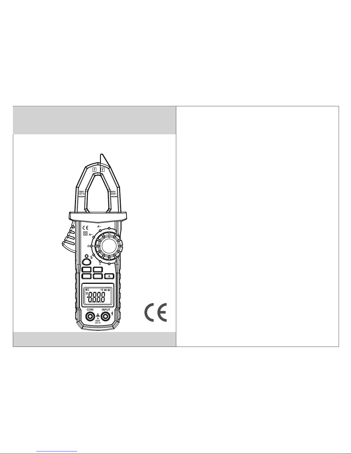
Clamp Meter User Manual
SEL
MAX
NCV
HOLD
OFF
AC CLAMP METER
200/600
2/20
V
OFF
RAN
AUTO MAX
°C°F
kMΩ
μmVA
MULTIFUNCTION DIGITAL
Page 2
CONTENTS
Safety requirements................................1
Safety signs......... ...................................1
Notes.......................................................1
Maintenance
................... ................... .....2
Overview.................................................3
Meter Indications
.......................................3
Schematic Drawing For Panel
.....................5
Instructions..............................................6
Accuracy Indicators...............................10
Automatic Power-Off...............................13
Replace Battery.....................................13
Accessories...........................................14
MULTIFUNCTION DIGITAL
Page 3
01
02
Safety Requirements
The MS200 9A digital c lamp meter has been designe d
accordi ng to Safet y Standard IEC61010-1
IEC6101 0-2-032 f or electronic measuring i nstrume nts
and hand- held curr ent clamps. It conforms to sa fety
standar ds for doub le insulation CAT III 600 V and
grade 2 for p ollutio n.
Safety Signs
Impor tant safet y sig n. Refer to th e operatio n manual.
Danger hi gh voltag e.
Double in sulatio n (Safety equipment with cl ass II).
Ground (e arth).
Allow to be u sed aroun d conductors without
danger to l ife.
Notes
• Before us ing this me ter, please read carefully t his
user manu al and pay sp ecial attention to “warni ng”
content . Please fo llow the “warning” instru ctions.
• To meet the saf ety requi rements, only use probe
supplie d with the me ter. If the probe is replaced,
a new one wit h the same mo del or same electric
specifi cation sh ould be used.
• Before us ing it, ple ase check the meter and probe
for any dam age or abno rmal condition. If an
abnorma l situati on appears (for example: ba re
probe, en closure d amage, no liquid crystal di splay,
etc), don 't use the me ter.
• When the me ter is meas uring, don't touch the unus ed
input ter minal.
• Be carefu l when meas uring voltage greater tha n 60V
DC and 30V AC. D on't allo w fingers to touch or block
part of the p robe.
• When you ca n't deter mine the size range of signal t o
be tested , please sw itch the function measuri ng range
to the maxi mum posit ion, then gradually selec t lower
ranges un til the cor rect range is found. Do not exc eed
the input l imit spec ified in each measuring ran ge.
• Don't mea sure volt age greater than the upper li mit for
each rang e.
• Before ch anging th e function measuring rang e switch
to a diff erent pos ition, se t the probe and the ci rcuit
being tes ted to an ope n state.
• Before on line resi stance measurement, tur n off all
power sup plies in ci rcuit and release all charg es on
both ends o f capacit or.
• Don't exp ose the met er exposure to strong light , high
tempera ture or moi sture (humidity).
• Don't tou ch bare wir es, connectors or circuit s being
measure d.
Maintenance
• Before op ening the m eter back cover, make sure tha t
the probe i s removed f rom the circuit to be measure d.
• Only wet cl oth and a sma ll amount of detergent can
be used for c leaning t he meter. Don't use chemical
solvent s to wipe the m eter case.
• If you find a ny abnorm al conditionon the meter, st oop
using the m eter imme diately and have it repaire d.
• Repair th e meter wit h the help of a trained technic ian.
MULTIFUNCTION DIGITAL MULTIFUNCTION DIGITAL
Page 4

03
04
Overview
The met er is a safe and reliable digital c lamp
meter w ith stable performance. Its design is based
on a larg e scale integrated circuit do uble integral
A/D con verter, wit h full measuring range of overl oad
prote ction circuit. With a unique ap pearance, it is a
speci al electrical meter with supe rior performance.
Meter Indications
1. AC current cla mp head
Pick AC current
2. NCV in dicator light
When th e voltage of conductor under te st is more
than AC 90V, the indicator will flash const antly.
3. SEL funct ion exchange key
When it i s in V position, it is used to switch between
DCV and ACV .
When it i s in position, it is used to switch between
diode m easurement and continuity m easurement.
4. Disp lay
LCD dis play (4 significant digits) .
5. COM in put end
In addi tion to AC curr ent, negative input end of
black p robe.
6. INPU T end
Red pro be positive input end when meas uring
volta ge, resistance, diode forwa rd voltage drop
and cir cuit continuity.
7. Func tion measuring switch
Used to s elect each function and measu ring range
grade .
8. Clam p head center position
To improve current measuremen t accuracy, pl ace
the con ductor to be measured in the cent er position.
9. NCV se nse position
When de tecting non-contact volta ge, position close
to the co nductor to be tested
Other Keys
Backlig ht
The meter d isplay is s et with backlight. Press th e key
for 2 secon ds to light . Press the key for 2 seconds aga in
to turn off the back light.
HOLD data h old key
Press “HO LD” key. Th e meter dis play will keep the last
test read ing; and sh ow “ ”symbol. Press “HOLD” ke y
again and t he meter wi ll restore to normal measur ing
state.
H
RAN Manual/Automatic Switch Key
In volt age and resistance measurem ent position, clamp
meter i s set to automatic measuring ra nge by default.
Press t his key to switch to manual measu ring range.
In the ma nual measuring range mode, cl ick the key once
to jump t o upper grade. If it is at the top grade, then it will
jump to t he bottom grade. Hold this key fo r 2 seconds to
switc h back to automatic measuring r ange.
MAX Max imum reading value display
Press “ MAX” key. The display w ill show the maximum
readi ng value among measuring data .
Press t he “MAX” key again. The meter will rev ert to
norma l measurement state
NCV Non -contact voltage detectio n switch Used for
non-c ontact voltage detection.
MULTIFUNCTION DIGITAL MULTIFUNCTION DIGITAL
Page 5

05
06
Sch ema tic D raw ing F or Pa nel
Instructions
DC Voltage Measure ment
1. Inse rt red probe to “INPUT” jack and in sert black
probe t o “COM” jack.
2. Plac e function measuring range sw itch to DC
volta ge measuring range. Press “SE L” key, and
conne ct the probe to the power source or l oad to be
tested. Th e polarity of the end connected w ith red
probe w ill be shown in the display at the sa me time.
3. Read t he measuring result from disp lay.
Notes!
∆ If the range of voltage to be tested is not known in
advan ce, place function measurin g switch to the
maxim um range, then gradually redu ce to obtain
the cor rect range.
∆ Pay spe cial attention to avoid shock w hen
measu ring high voltage.
AC Voltage Measure ment
1. Inse rt red probe to “INPUT” jack and in sert black
probe t o “COM” jack.
2. Plac e function measuring range sw itch to AC
volta ge measuring range, and conne ct the probe
to the power source or load to be tested. The
polar ity of the end connected with red p robe will
be show n in the display at the same time.
3. Read t he measuring result from disp lay.
Notes!
∆ Pay spe cial attention to avoid shock w hen
measu ring high voltage.
1
2
3
4
9
6
7
8
5
SEL
MAX
NCV
HOLD
OFF
AC CLAMP METER
200/600
2/20
V
OFF
RAN
AUTO MAX
°C°F
kMΩ
μmVA
MULTIFUNCTION DIGITAL MULTIFUNCTION DIGITAL
Page 6

07
08
AC Current Measurement
1. Plac e function measuring range sw itch to AC
curre nt measuring range.
2. Pres s the trigger, open clamp head, clip the lead
in the cl amp to measure the lead current . Note:
Clamp ing two or more leads at the same tim e will
give in valid reading.
3. Read t he measuring result from disp lay.
Notes!
∆ If the range of current to be tested is not known in
advan ce, please place function mea suring switch
to the maximum current range, then gradually
reduc e to obtain the correct range.
Resistance Measurement
1. Inse rt red probe and black probe to “IN PUT” and
“COM” jack.
2. Plac e function measuring range sw itch to required
Ω position, and connect the probe to resistor to
be tested.
3. Read t he measuring result from disp lay.
Note:
∆ If measured resistance value is more than the
maxim um value of chosen measuring ra nge, it will
show wi ll “OL`”. At th is time, select a higher range.
∆ When ch ecking online resistance, f irst turn off all
power s upplies in the circuit to be meas ured and
disch arge all capacitors fully.
∆ When me asuring the resistance more t han 1MΩ,
the rea ding will be stable after sever al seconds.
This is norm al for high resistance measur ing.
Diode Test
Inser t red probe to “INPUT” and insert black probe to
“COM” j ack. At this ti me, red probe polarity is “+”.
Place f unction measuring switch to position. Red
probe i s connected to the anode of diode u nder
measu rement, and black probe is conn ected to the
catho de of diode under measurement . Read
appro ximate forward voltage drop v alue from the display.
Circuit Continuity Test
Inser t red probe to “INPUT” jack, and insert black
probe t o “COM” jack. Place function me asuring switch
to position and press SEL key to enter circuit
conti nuity test. Probe is connecte d to two points of
circu it under measurement. In cont inuity test, when
test re sistance is less than 50Ω, buzz er will sound.
When it i s from 50Ω to 90Ω, buzzer may or may not
sound . When it is more than 90Ω, buzzer wo n't sound.
Non-Contact Volt age Detection
Press N CV key. Place non- contact sensor close to the
condu ctor. When te st voltage is greater than 90V AC
(RMS) a nd when the meter is close to the con ductor,
the met er induction voltage indica tor will flash and
buzze r will sound.
Note:
1: Even t here is no indication, voltag e may exist. Don't
use non -contact voltage detector to judge whether
there i s voltage in the wire. Detectio n operation
could b e aff ected by socket design, insul ation
thick ness, type and other factors.
MULTIFUNCTION DIGITAL MULTIFUNCTION DIGITAL
Page 7

09
10
2: When i nputting voltage on the meter i nput terminal,
due to the existence of the induced voltage, voltage
induc tion indicator also may light .
3: Inte rference sources of externa l environment (such
as flas hlight, motor, etc.) may trigger non-con tact
volta ge detection by mistake.
Technical Data
Gener al characteristics: the max imum voltage of
volta ge input end and ground CAT III 600V and
600V~
Displ ay method: LCD display with max imum of 1999
Measu ring principle: double inte gral A/D conv ertion
Measu ring range choice: Automatic
Measu rement speed: 3 times/s
Unit di splay: has function and power u nit symbol
displ ay Polarity indication: dis play “-” symbol for
negat ive polarity input
Overr ange display: “OL”
Data ho ld function: display “ ” on the top of LCD
Low bat tery display: display “ ” on the top of LCD
Power b attery: DC1.5V Х3 S IZE AAA.
Outsi de measurement: 220mm×81m m×41mm
Weight: ab out 286g (include battery)
The lar gest size of open clamp jaw: 26mm
Opera ting environment: 5°C~35° C
Stora ge temperature: -10°C~50° C
H
Accuracy Indicators
Accur acy: ±(% of reading + digits) wit h one year of
warra nty Environment temperatu re: 18°C~28°C
Envir onment humidity: not more tha n 75%
Temperature coefficient: 0.1 × Accuracy/ 1° C
* When me asuring AC cu rrent,
place t he conductor to
be meas ured be in the center
posit ion of clamp head.
If it is not in the center
posit ion, it can increase
error b y 1.5%
DC Voltage
1mV
10mV
±(0.6% of reading + 3 digits)
200mV
2V
20V
600V
0.1mV
1V
±(0.8% of reading + 3 digits)
Measuring
range
Resolution
Accuracy
200V 0.1V
Input i mpedance: 10MΩ.
Maxim um allowable input voltage: 6 00V DC or 600V
AC (RMS )
Sign
Condctor
Sign
Sign
MULTIFUNCTION DIGITAL MULTIFUNCTION DIGITAL
Page 8

11
12
DC Voltage
1mV
10mV
±(0.8% of reading + 5 digits)
200mV
2V
20V
600V
0.1mV
1V
±(1.0% of reading + 5 digits)
Measuring
range
Resolution
Accuracy
200V 0.1V
Input i mpedance: 10MΩ.
Measu ring frequency range: 40Hz~ 400Hz.
Maxim um allowable input voltage: 6 00V DC or 600V
AC (RMS )
±(2.0% of reading + 3 digits)
AC Current
0.001A
0.01A
2A
20A
600A
1A
Measuring
range
Resolution
Accuracy
200A 0.1A
Measu ring frequency range: 0~500 A 40Hz ~400Hz ;
500A~600A 60Hz~400Hz.
Maxim um allowable input current: AC 600A for not
more th an 20 seconds.
±(2.0% of reading + 5 digits)
Resolution
Accuracy
200Ω
2kΩ
0.1kΩ
0.001kΩ
0.1Ω
0.01kΩ
0.01MΩ
0.001MΩ
Resistance
20kΩ
200kΩ
2MΩ
20MΩ
±(1.2% of rdg + 5digits)
Overloa d protect ion: 250V DC or 250V AC (RMS)
Measuring range
±(0.8% of rdg +4digits)
1mV
Display approximate value of
forward voltage drop (Open
circuit voltage is about 1.5V)
Diode Test
Overloa d protect ion: 250V DC or 250V AC (RMS)
Accuracy
Measuring
range
Resolution
The buzzer will sound when it is
<60Ω (Open circuit voltage is
about 0.45V)
Continuity Test
Note: Whe n resista nce is from 60Ω to 90Ω, the buzze r
may or may no t sound. Wh en it is more than 90Ω, the
buzzer wo n't sound .
Overloa d protect ion: 250V DC or 250V AC (RMS)
100MΩ
Measuring
range
Resolution
Accuracy
MULTIFUNCTION DIGITAL MULTIFUNCTION DIGITAL
Page 9

13
14
Automatic Power-Off
In order to e xtend the b attery life, the meter has an
automat ic shutdo wn function. If there is no key
operati on or funct ion measuring range chang e
within 15 m inutes, t he meter power will disconn ect
automat ically. Press “SEL” button to retur n the
meter to th e working s tate again.
Replace Battery
To avoid e lectric s hock, disconnect the prob e
before op ening bat tery cover. Disconnect any
circuit o r signal be ing tested. Use only a
battery w ith the sam e model or same electric
specifi cation.
Warning
If “ ” symbol a ppears, i t means that the battery
should be r eplaced . Before opening the meter ba ck
cover, mak e sure that n o probe is connected to the
circuit . Check tha t the back cover is tightened
before us ing the met er., Follow these steps to
replace t he batter y:
1. Discon nect the pr obe and remove it from the
input jac k. Switch r otating function measur ing
range swi tch to “OFF ”.
2. Unscre w screws on t he battery cover and remove
the batte ry cover.
3. Take out the old batt eries and r eplace with three
new 1.5 V SIZ E AAA batteri es.
Replace t he batter y cover and tighten screws.
Accessories
User Manu al
Probe
Packing b ox
1.5V SIZE AA A Battery
1 pc
1 pair
1 pc
3 pcs
HYS007093
MULTIFUNCTION DIGITAL MULTIFUNCTION DIGITAL
 Loading...