

Page 1
01
02
03
04 05
OPERATOR'S
INSTRUCTION MANUAL
Safe ty Info rmati on
The dig ital cl amp met er has be en desi gned ac cordi ng to IEC
1010- 1 and IEC 1010- 2-032 c oncer ning sa fety re quire ments
for ele ctric al meas uring i nstru ments a nd hand – h eld cur rent
clamp s with ov ervol tage ca tegor y 1000V C AT II 600V C AT III
and pol lutio n 2.
Safe ty Symb ols
Safe ty Prec autio ns
DIGITAL CLAMP METER
Impor tant sa fety in forma tion, r efer to t he
opera ting ma nual.
Dange rous vo ltage m ay be pre sent.
Earth g round .
Doubl e insul ation ( P rotec tion cl ass 100 0V
CAT II 600 V CAT III ).
The dig ital cl amp met er comp lies wi th the re quire ments o f the
follo wing Eu ropea n Commu nity Di recti ves: 89 /336/ EEC ( Ele ctroma gneti c Compa tibil ity ) and 7 3/23/ EEC ( Low Vo ltage ) a s
amend ed by 93/ 68/EE C ( CE Mark ing ).
Howev er, elec trica l noise o r inten se elec troma gneti c field s in
the vic inity o f the equ ipmen t may dis turb th e measu remen t
circu it.Me asuri ng inst rumen ts will a lso res pond to u nwant ed
signa ls that m ay be pre sent wi thin th e measu remen t circu it.
Users s hould e xerci se care a nd take a pprop riate p recau tions
to avoi d misle ading
Follo w all saf ety and o perat ing ins truct ions to e nsure m aximu m
perso nal saf ety dur ing the o perat ion and t o ensur e the met er is
used sa fely an d is kept i n good op erati ng cond ition .
• Read th ese ope ratin g instr uctio ns thor oughl y and com plete ly
befor e opera ting yo ur mete r. Pay par ticul ar atte ntion t o
WARNI NGS, wh ich wil l infor m you of po tenti ally da ngero us
proce dures . The ins truct ions in t hese wa rning s must be f ollow ed.
• Alway s inspe ct your m eter an d test le ads for a ny sign o f
damag e or abno rmali ty befo re ever y use. If a ny abno rmal
condi tions e xist (i .e. bro ken tes t leads , crack ed case s, disp lay
not rea ding, e tc.), d o not att empt to t ake any m easur ement s.
• Do not ex pose th e instr ument t o direc t sunli ght, ex treme
tempe ratur e or mois ture.
• Never g round y ourse lf when t aking e lectr ical me asure ments .
Do not to uch exp osed me tal pip es, out lets, f ixtur es, etc ., whic h
might b e at grou nd pote ntial . Keep yo ur body i solat ed from
groun d by usin g dry clo thing ; rubbe r shoes , rubbe r mat, or a ny
appro ved ins ulati ng mate rial.
• You alwa ys are ca reful w hen wor king wi th volt ages ab ove 60V
dc or 30V a c rms. Ke ep fing ers beh ind the p robe ba rrier s while
measu ring.
• Never u se the me ter to me asure v oltag es that m ight ex ceed
the max imum al lowab le inpu t value o f any fun ction .
• Never t ouch ex posed w iring , conne ction s or any li ve circ uit
when at tempt ing to ta ke meas ureme nts.
• Befor e openi ng the ca se, alw ays dis conne ct test l eads fr om all
energ ized ci rcuit s.
• Never u se the me ter unl ess the b ack cov er is in pl ace and
faste ned com plete ly.
• Do not us e abras ives or s olven ts on the m eter. To cle an it usi ng
a damp cl oth and m ild det ergen t only.
Main tenan ce
• Quali fied an d train ed serv ice tec hnici ans sho uld onl y perfo rm
calib ratio n and rep air of th e meter.
• Do not at tempt c alibr ation o r servi ce unle ss trai ned and a nothe r
perso n capab le of ren derin g first a id and re susci tatio n is pres ent.
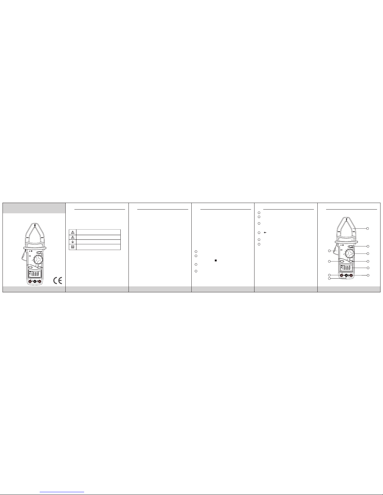
Gene ral Des cript ion
The me ter is a ha ndhel d 3 1/2 dig ital cl amp met er for
meas uring D C and AC vol tage, AC c urren t, Resi stanc e,
Diod e and Con tinui ty Test with b atter y opera ted.
“ ” jack
This i s the pos itive i nput te rmina l for ohm s and dio de.
Conn ectio n is made t o it usin g the red t est lea d.
Powe r Switc h
A push pu sh swit ch is use d to turn t he mete r on or off.
Trigg er
Pres s the lev er to ope n the tra nsfor mer jaw s. When t he
leve r is rele ased, t he jaws w ill clo se agai n.
Ω
8
Fron t Panel D escri ption
Trans forme r jaws
Pick u p the AC cur rent fl owing t hroug h the con ducto r.
Hold b utton
When t his but ton is pu shed, t he disp lay wil l keep th e
last r eadin g and “ ” sym bol wil l appea r on the LC D
unti l pushi ng it aga in.
Rota ry swit ch
This s witch i s used to s elect f uncti ons and d esire d
rang es.
Back l ight
To use thi s funct ion, pr ess the L IGHT but ton. Wh en this
butt on is pus hed, th e Back li ght of di splay i s on. Afte r
abou t 3 5 secon ds, the B ack lig ht is sel f-off. T he Back
ligh t is on aga in, jus t push th is butt on once .
1
2
3
4
5
6
7
H
Disp lay
3 1/2 di git, 7 se gment , 16mm hi gh, LCD .
“V” ja ck
This i s posit ive inp ut term inal fo r VOLT meas ureme nts
conn ectio n is made t o it usin g the red t est lea d.
“COM ” jack
This i s negat ive ( gro und ) inp ut term inal fo r all
meas ureme nt mode s excep t curre nt. Con necti on is
made t o it usin g the bla ck test l ead.
CLA MP METE R LAYOUT
9
10
DIGITAL CLAMP METER DIGITAL CLAMP METER DIGITAL CLAMP METER DIGITAL CLAMP METER DIGITAL CLAMP METER
1
3
2
4
5
5
7
8
9
10
°C
Ω
V
A
KHz
2
20
200
~
1000A
~
200A
750V
~
1000V
1000Ω
2000Ω
200Ω
ONOFF
LIGHT
CLAMP METER
DC
AC
~
Ω
COM
V
1000V CAT ll
600V CAT lll
MAX 1000A~
1000V CAT ll
600V CAT lll
HOLD
°C
Ω
V
A
KHz
2
20
200
~
1000A
~
200A
750V
~
1000V
1000Ω
2000Ω
200Ω
ONOFF
LIGHT
CLAMP METER
DC
AC
~
Ω
COM
V
1000V CAT ll
600V CAT lll
MAX 1000A~
1000V CAT ll
600V CAT lll
HOLD
Page 2
1108 09 1006 07 11
HYS 00662 1
NOTE :
3. Con nect te st lead s acros s the res istor t o be meas ured
and re ad LCD di splay.
4. If th e resis tance b eing me asure d is conn ected t o a
circ uit, tu rn off pow er and di schar ge all ca pacit ors
befo re appl ying te st prob es.
1. If th e resis tance b eing me asure d excee ds the
maxi mum val ue of the r ange se lecte d or the in put is
not co nnect ed, an ov erran ge indi catio n “1”wi ll be
disp layed .
2. Whe n check ing in- circu it resi stanc e, be sur e the
circ uit und er test h as all po wer rem oved an d that al l
capa citor s have be en disc harge d fully.
Audi ble Con tinui ty Test
1. Con nect re d test le ad to “ ” jac k, blac k test le ad to
“COM ” jack.
2. Set r ange sw itch to “ ” p ositi on.
3. Con nect te st lead s to two po ints of c ircui t to be tes ted.
If con tinui ty exis ts, bui lt-in b uzzer w ill sou nd.
Diod e Test
1. Con nect th e red tes t lead to “ ” j ack and t he blac k
test l ead to th e “COM” j ack (Th e polar ity of re d lead
is pos itive “ +”.).
2. Set t he rota ry swit ch at “ ” pos ition .
3. Con nect th e red tes t lead to t he anod e of the di ode to
be tes ted and t he blac k test le ad to the c athod e of the
diod e. The app rox. fo rward v oltag e drop of t he diod e
will b e displ ayed. I f the con necti on is rev ersed , only
figu re “1” wi ll be sho wn.
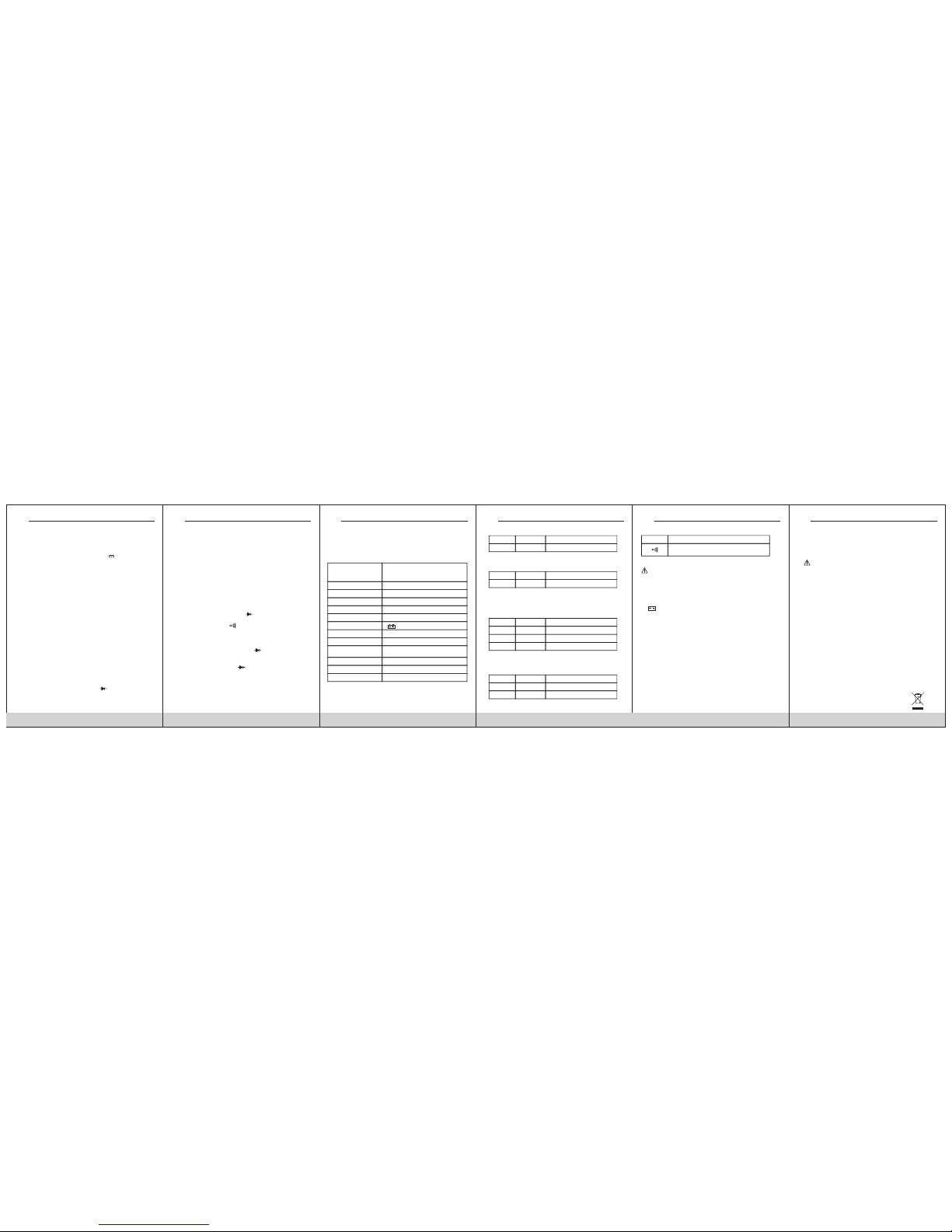
Spec ifica tions
Accu racy is s pecif ied for a p eriod o f one yea r after
cali brati on and at 1 8°C to 28 °C(64° F to 82° F) with r elati ve
humi dity to 8 0%.
Gene ral
Maximum voltage
between terminals
and earth ground
CAT II 1000V and CAT III 600V
Display
LCD,1999 counts, updates 2-3/ sec.
“-”displayed for negative polarity.
Only figure “1” on the display.
42mm (Max conductor size)
9V battery, NEDA 1604 6F22 006P.
“ ”Appears on the display.
0 to 40°C
-10°C to 50°C
0.1×specified accuracy) / °C
(<18°C or >28°C)
Temperature coefficient
Storage temperature
Operating Environment
Low battery indication
Power
Polarity indication
Overrange Indication
Jaw opening capability
Altitude
Size
Weight
2000m
250mm×99mm×43mm
Approx.460g.
DC Volta ge
Range
Resolution
Accuracy
1000V
1V
±1.0% of rdg ±2 digits
Inpu t Imped ance: 1 0MΩ
AC Volta ge
Range
Resolution
Accuracy
750V
1V
±1.0% of rdg ±5 digits
Inpu t Imped ance: 1 0MΩ
Freq uency r ange: 4 0Hz to 40 0Hz. Re spons e: Averag e
resp ondin g, cali brate d in rms. o f a sine wa ve.
Range
Resolution
Accuracy
20A 0.01A
± 2.0% of rdg ±5 digits
AC Cur rent
200A
1000A
0.1A
1A
± 2.0% of rdg ±5 digits
± 2.0% of rdg ±7 digits
Over load Pr otect ion: 12 00A for 60 s econd s maxim um.
Freq uency r ange: 5 0Hz to 60 Hz.
Resi stanc e
Range
Resolution
Accuracy
200Ω 0.1Ω
± 1.0% of rdg ± 3 digits
2000Ω 1Ω
± 1.0% of rdg ± 3 digits
Repl acing T he Batt ery
WARNING
Cont inuit y
Range
Description
If con tinui ty exis ts (abo ut less t han 20Ω ),
buil t-in bu zzer wi ll soun d.
Befo re atte mptin g to open t he case o f batte ry, alway s
be sur e that te st lead s have be en disc onnec ted fro m
meas ureme nt circ uits. C lose ca se and ti ghten s crews
comp letel y befor e using t he mete r to avoi d elect rical
shoc k hazar d.
If “ ”ap pears o n displ ay, it indi cates t hat the b atter y
shou ld be rep laced . Use the f ollow ing pro cedur e to
repl acing t he batt ery:
1. Dis conne ct test l eads fr om any li ve sour ce and re move
the te st lead s from th e input t ermin als of th e meter.
Push t he POWE R switc h to OFF,
2. The ba ttery c over is s ecure d to the bo ttom ca se by a
scre w. Using a s crewd river, r emove t he scre w from
the ba ttery c over an d remov e the bat tery co ver.
3. Rem ove bat tery an d repla ce with a n ew equi valen t 9
volt b atter y.
4. Rep lace th e batte ry cove r and rei nstal l the scr ew.
Acce ssori es
• Oper ator' s instr uctio n manua l
• Set of t est lea ds
• Gift b ox
• 9 volt b atter y. NEDA 1604 6 F22 006 P type.
CAUTION:
Usin g this ap plian ce in an en viron ment wi th a stro ng
radi ated ra dio-f reque ncy ele ctrom agnet ic fiel d
(app roxim ately 3 V/m), m ay infl uence i ts meas uring
accu racy. The m easur ing res ult can b e stron gly
devi ating f rom the a ctual v alue.
Oper ating I nstru ction s
DC Volta ge Meas ureme nt
1. Con nect th e red tes t lead to t he “V” ja ck and th e black
lead t o the “CO M” jack .
2. Set r otary s witch a t desir ed 1000 V posit ion.
3. Con nect te st lead s acros s the sou rce or lo ad bein g
meas ured.
4. Rea d volta ge valu e on the LC D displ ay alon g with th e
pola rity of t he red le ad conn ectio n.
AC Volta ge Meas ureme nt
1. Con nect th e red tes t lead to “ V~” jac k and the b lack
test l ead to th e “COM” j ack.
2. Set t he rota ry swit ch at des ired 75 0V~ pos ition .
3. Con nect te st lead s acros s the sou rce or lo ad bein g
meas ured.
4. Rea d volta ge valu e on the LC D displ ay.
AC Cur rent Me asure ment
1. Set t he rota ry swit ch at des ired A~ po sitio n.
2. Pre ss the tr igger t o open tr ansfo rmer ja w and to cl amp
one co nduct or only, ma king su re that t he jaw is f irmly
clos ed arou nd the co nduct or.
3. Rea d curre nt valu e on LCD di splay.
4. Whe n only th e figur e “1” is di splay ed, it in dicat es
over range s ituat ion and t he high er rang e has to be
sele cted.
Resi stanc e Measu remen t
1. Con nect th e red tes t lead to “ ” j ack and b lack
test l ead to th e “COM” j ack (Th e polar ity of re d lead
is pos itive “ +”).
2. Set t he rota ry swit ch at des ired“ ” range p ositi on.
Ω
Ω
Ω
Ω
DIGITAL CLAMP METER DIGITAL CLAMP METER DIGITAL CLAMP METER DIGITAL CLAMP METER DIGITAL CLAMP METER DIGITAL CLAMP METER
 Loading...