

Page 1

OPERATOR’S
• AUTO-RANGE
• DUAL DISPLAY
• CONFORMED IEC1010
DIGITAL MULTIMETER
INSTRUCTION MANUAL
Page 2

CONTENTS PAGE
SAFETY INFORMATION ….……………….…………………………………………...
DESCRIPTION …….………….…………………………………………………………
OPERATING INSTRUCTION ..…………………………………………………………
SPECIFICATIONS ………….…...………………………………………………………
ACCESSORIES ………….………………………………………………………………
BATTERY AND FUSE REPLACEMENT ……………...………………………………
1
5
10
17
26
27
Page 3

1. SAFETY INFORMATION
The meter has been designed according to IEC-1010 concerning electronic measuring
instruments with an overvoltage category (CAT II) and pollution 2.
Follow all safety and operating instructions to ensure that the meter is used safely and is
kept in good operating condition.
1.1 PRELIMINARY
·
When using the meter, the user must observe all normal safety rules concerning :
-Protection against the dangers of electrical current.
-Protection of the meter against misuse.
Full compliance with safety standards can be guaranteed only if used with test
·
leads supplied. If necessary, they must be replaced with the same model or same
-1-
Page 4

electric ratings. Measuring leads must be in good condition.
1.2 DURING USE
·
Never exceed the protection limit values indicated in specifications for each range
of measurement.
When the meter is linked to a measurement circuit, do not touch unused terminals.
·
When the value scale to be measured is unknown beforehand, set the range
·
selector at the highest position.
Before rotating the range selector to change functions, disconnect test leads from
·
the circuit under test.
When carrying out measurements on TV or switching power circuits, always
·
remember that there may be high amplitude voltage pulses at test points, which
-2-
Page 5
can damage the meter.
Never perform resistance measurements on live circuits.
·
Always is careful when working with voltages above 60V dc or 30V ac rms. Keep
·
fingers behind the probe barriers while measuring.
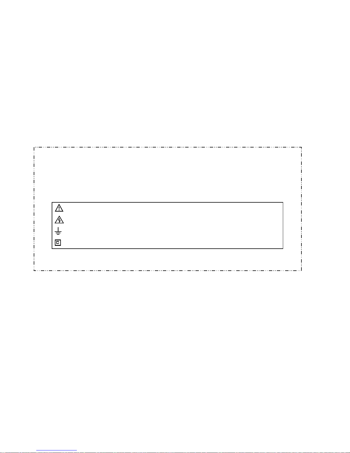
1.3 SYMBOLS
Important safety information, refer to the operating manual.
Dangerous voltage may be present.
Earth ground.
Double insulation (Protection class II).
-3-
Page 6

1.4 MAINTENANCE
·
Before opening the meter, always disconnect test leads from all sources of electric
current.
For continue protection against fire, replace fuse only with the specified voltage
·
and current ratings:
F 15A/250V
If any faults or abnormalities are observed, the meter can not be used any more
·
and it has to be checked out.
Never use the meter unless the back cover is in place and fastened fully.
·
To clean the meter, use a damp cloth and mild detergent only, do not use
·
abrasives of solvents on it.
-4-
Page 7

2. DESCRIPTION
This meter is an autoranging professional measuring instrument. Digit reading is 3999
counts and the bar graph consists of 38 segments for LCD, capable of performing
functions:
-DC voltage measuring (Auto Ranging)
-AC voltage measuring (Auto Ranging)
-DC current measuring
-AC current measuring
-Temperature measuring
-Resistance measuring (Auto Ranging)
-Capacitance measuring
-5-
Page 8
-Diode testing
-Transistor testing
-Audible continuity testing
2.1 ON/OFF SWITCH
A push − push switch is used to turn the meter on or off. When the switch is push the
beeper will sound.
2.2 DC/AC OR Ω /
BUTTON
This button is used to select DCV or ACV on voltage range, DCA or ACA on current
range, Ω or
on Ω / range. When the button is push the beeper will sound.
2.3 R-H BUTTON
In auto-range, press this button to select manual range and “R-H” symbol will appear on
-6-
Page 9

the LCD. Press the button again for more than 1 second will come back the auto-range
mode.
When the R-H button is pushed, voltage ranges will change as:
4V → 40V → 400V → 1000V
Or resistance ranges change as:
40MΩ → 4MΩ → 400kΩ → 40kΩ → 4kΩ → 400Ω
2.4 B/L BUTTON
Press this button to toggle back-lit ON. The screen of the meter will light. Press the
button again, back-lit turn off.
-7-
Page 10
2.5 INPUT JACKS
This meter has four input jacks that are protected against overload to the limits. During
use, connect the black test lead to the COM jack and the red test lead as shown below:
FUNCTION RED LEAD CONNECTION INPUT LIMITS
DCV/ACV
Ω
mA
10A
V/Ω
V/Ω
V/Ω
mA
10A
1000V dc or 750V rms ac
250V dc or rms ac
250V dc or rms ac
400mA dc or rms ac
10A dc or rms ac
-8-
Page 11

2.6 FRONT PANEL
. DISPLAY
. ON/OFF SWITCH
.TRANSISTOR TESTING SOCKET
. FUNCTION SWITCH
. CAPACITANCE OR TEMPERATURE
TESTING SOCKET
. INPUT JACKS
. RS232C SOCKET
. B/L BUTTON
. R-H BUTTON
. DC/AC OR Ω / BUTTON
1
2
3
4
5
6
9
8
7
Page 12

-9-
3. OPERATING INSTRUCTION
3.1 VOLTAGE MEASURING
Connect the black test lead to the COM jack and the red test lead to the
1.
V/Ωjack.
2.
Set the function switch at V range and connect test leads across the source or
load under measurement.
3.
Push the DC/AC button to select DCV or ACV measuring mode. (Push the R-H
button to select manual range.)
4.
Read LCD display. The polarity of red test lead connection will be indicated
when making a DC measurement.
3.2 CURRENT MEASURING
Page 13

1. Connect the black test lead to the COM jack and the red test lead to the mA jack
for a maximum of 400mA. For a maximum of 10A, move the red lead to the 10A
jack.
Set the function switch at mA or 10A range and push the DC/AC button to select
2.
DCA or ACA measuring mode.
Connect test leads in series with the load in which the current is to be
3.
measured.
4.
Read LCD display. The polarity of red test lead connection will be indicated
when making a DC measurement.
3.3 RESISTANCE MEASURING
1. Connect the black test lead to the COM jack and the red teas lead to the V/Ω
jack. (NOTE: The polarity of the red test lead connection is positive “+”)
-10-
Page 14

2. Set the function switch at Ω range to be used and connect test leads across the
resistance under measurement.
-11-
NOTE:
For resistance above 1MΩ, the meter may take a few seconds to stabilize
1.
reading. This is normal for high resistance measuring.
When the input is not connected, i.e. at open circuit, the figure “OL” will be
2.
displayed and full bar graph appears for the overrange condition.
When checking in-circuit resistance, be sure the circuit under test has all power
3.
removed and all capacitors fully discharged.
3.4 CAPACITANCE MEASURING
Page 15

1.
Set the function switch at nF range.
2.
Before inserting capacitor under measurement into capacitance testing socket,
be sure that the capacitor has been discharged fully.
WARNING:
Before attempting to insert capacitor for testing, always be sure that test leads have
been disconnected from any measurement circuits.
Components should not be connected to the capacitor socket when making voltage
measurements with test leads.
3.5 TEMPERATURE MEASURING
1. Set the function switch at TEMP range.
-12-
Page 16

2. Insert “K” type thermocouple into the temperature measuring socket on front
panel and contact the object to be measured with the thermocouple probe.
-13-
WARNING:
To avoid electric shock, be sure the thermocouple has been removed before changing
to another function measurement. Before attempting to insert thermocouple for testing,
always be sure that test leads have been disconnected from any measurement circuits.
3.6 AUDIBLE CONTINUITY TESTING
Page 17

1.
Connect the black test lead to the COM jack and the red test lead to the V/Ω
jack. (NOTE: The polarity of red test lead connection is positive “+”)
2.
Set the function switch at
Connect test leads to two points of the circuit under measurement. If continuity
3.
position and push the Ω/ button.
exists (i.e., the resistance is lower than 30Ω), built-in buzzer will sound.
3.7 DIODE TESTING
1. Connect the black test lead to the COM jack and the red test lead to the V/Ω
jack.
(NOTE: The polarity of the red test lead connection is positive “+” )
2.
Set the function switch at
Connect the red test lead to the anode of the diode to be tested and the black
3.
test lead to the cathode.
position.
-14-
Page 18

4. Read LCD display to get the forward voltage drop of the diode under testing.
3.8 TRANSISTOR TESTING
1.
Set the function switch at hFE position.
2.
Determine whether the transistor is NPN or PNP type and locate emitter, base,
and collector lead Insert leads of the transistor into proper holes of the transistor
testing socket on the front panel.
3.
The meter will show the approx. hFE value at test condition of base current
10μA and Vce 3.0V.
-15WARNING:
Before attempting to insert transistor for testing, always be sure that test leads have
been disconnected from any measurement circuits.
Page 19

Components should not be connected to the transistor socket when making voltage
measurements with test leads.
3.9 INTERFACING THE METER WITH A PC (OPTION)
1.
Connect the RS232C cable between the meter and computer’s serial ports.
2.
Press ON/OFF to turn on the meter. Turn on the computer.
WARNING:
1. Use only the type of serial interface cable RS232C cable exclusively designed
for your meter. Never attempt to modify of extend the length or RS232C cable.
2.
Please read this file of readme from Disks.
4. SPECIFICATIONS
-16-
Page 20

Accuracy is specified for a period of one year after calibration and at 18℃ to 28℃
(64°F to 82°F) with relative humidity to 75%.
4.1 GENERAL
Max. Voltage Between Terminals and Earth Ground: 1000V dc or 750V rms ac (sine)
Power Supply: 9V NEDA1604 6F22 006P
Ranging Method: Auto / Manual
Display: LCD, 3999 counts max and bar graph consists of 38 segments
-17-
Page 21

Overrange Indication: “OL” displayed
Polarity Indication: “-” displayed automatically
Low Battery Indication: “
”displayed
Operating Temperature: 5℃to 35℃(41°F to 95°F)
Storage Temperature: -10℃ to 60℃(14°F to 140°F)
Dimension: 78mm×186mm×35mm
Weight: 300g(Including battery)
-18-
Page 22

4.2 DC VOLTAGE
Range Resolution Accuracy
4V 1mV
40V 10mV
400V 0.1V
1000V 1V ±0.8% of rdg±3 digits
Input Impedance: 10MΩ.
-19-
±0.5% of rdg±3 digits
Page 23

4.3 AC VOLTAGE
Range Resolution Accuracy
4V 1mV
40V 10mV
400V 0.1V
750V 1V ±1.5% of rdg±5 digits
Input Impedance: 10MΩ
Frequency Range: 40 to 400Hz
Response: Average, calibrated in rms of sine wave.
±1.2% of rdg±5 digits
-20-
Page 24

4.4 RESISTANCE
Range Resolution Accuracy
400Ω 0.1Ω
4kΩ 1Ω
40kΩ 10Ω
400kΩ 0.1kΩ
4MΩ 1kΩ
40MΩ 10kΩ ±3.0% of rdg±5 digits
Maximum Open Circuit Voltage: 3.0V
Overload Protection:250V dc or rms.ac for all ranges.
-21-
±1.2% of rdg±3 digits
Page 25

4.5 DC CURRENT
Range Resolution Accuracy
4mA 1μA
400mA 0.1mA
10A 10mA ±2.0% of rdg±8 digits
Overload Protection: F 15A/250V fuse for 10A range.
±1.2% of rdg±3 digits
-22-
Page 26

4.6 AC CURRENT
Range Resolution Accuracy
4mA 1μA
400mA 0.1mA
10A 10mA ±3.0% of rdg±8 digits
Overload Protection: F 15A/250V fuse for 10A range.
Frequency Range: 40 to 400Hz
Response: Average, calibrated in rms of sine wave.
-23-
±1.5% of rdg±8 digits
Page 27

4.7 CAPACITANCE
Range Resolution Accuracy
4nF 1pF
400nF 0.1nF
4.8 TEMPERATURE
Range Resolution Accuracy
0℃ to 400℃ 1℃ ±3.0% of rdg±3 digits
401℃ to 750℃ 1℃ ±3.0% of rdg±5 digits
±4.0% of rdg±5 digits
-24-
Page 28

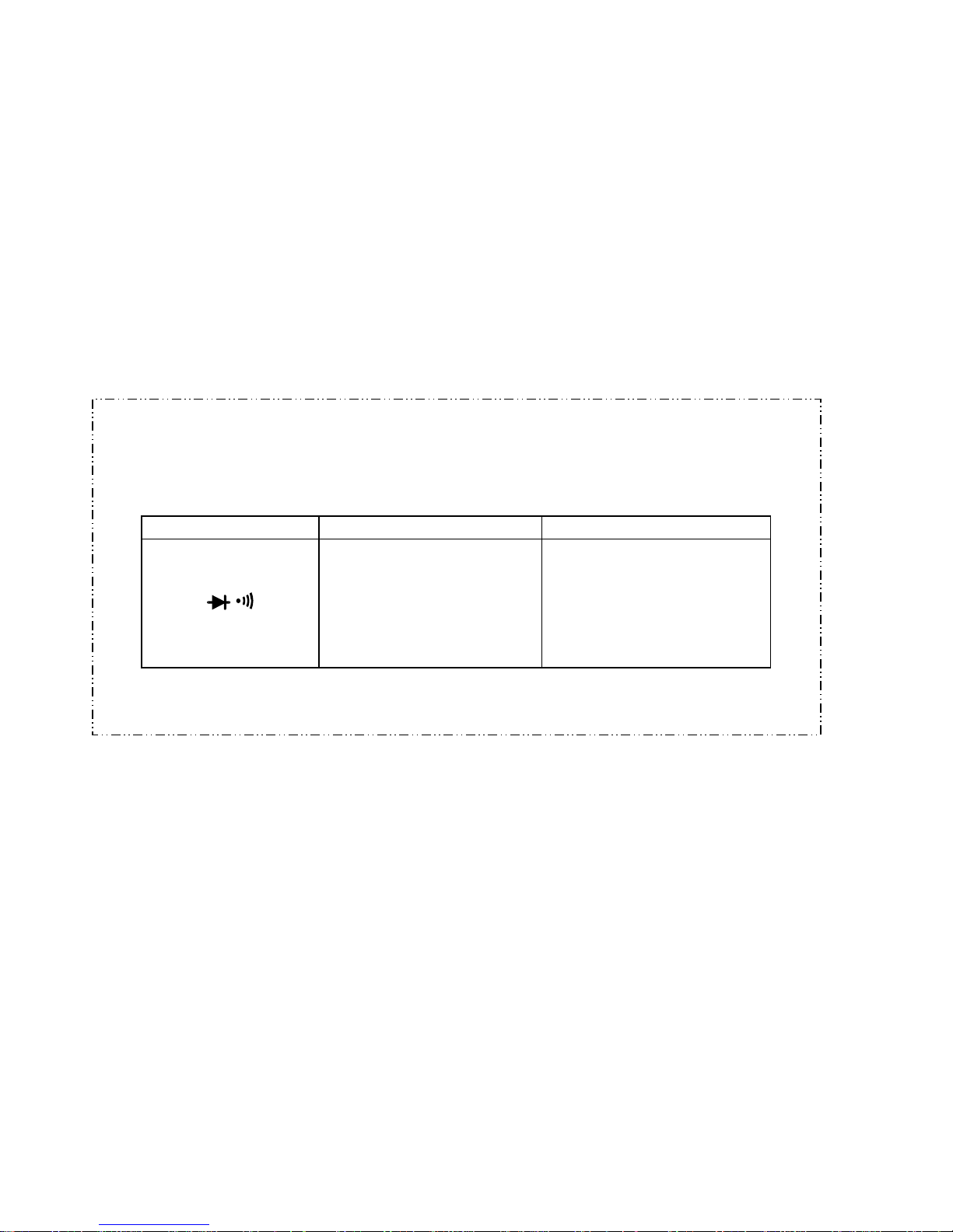
4.9 AUDIBLE CONTINUITY
Function Description
Built-in buzzer will sound, if resistance is lower than 30Ω.
4.10 DIODE
Function Resolution Test Current Open Circuit Voltage
1mV 25μA 3.0V
4.11 TRANSISTOR
Function Range Base Current Vce
hFE 1 to 1000 10μA 3.0V
-25-
Page 29

5. ACCESSORIES
5.1 SUPPLIED WITH THE METER
Operating Manual
•
Set of test leads
•
9V battery. NEDA1604 6F22 006P
•
“K” type thermocouple
•
5.2 OPTIONAL ACCESSORY
Holster
•
RS232C Cable
•
Set of 3.5” 1.44MB disk
•
-26-
Page 30

6. BATTERY AND FUSE REPLACEMENT
If the sign “
” appears on the LCD display, it indicates that the battery should be
replaced. Remove screws on the back cover and open the case. Replace the exhausted
battery with a new one.
Fuse rarely need replacement and blow almost always as a result of the operator’s error.
Open the case as mentioned above and take the PCB assembly out from the case.
Replace the blown fuse with ratings specified.
WARNING:
Before attempting to open the case, be sure that test leads have been disconnected
from measurement circuit to avoid electric shock hazard.
For protection against fire, replace fuses only with specified ratings: F 15A/250V
-27-
Page 31

°F=( °C ×1.8+32 )
HYS004695 A0
 Loading...