

Page 1
01 04
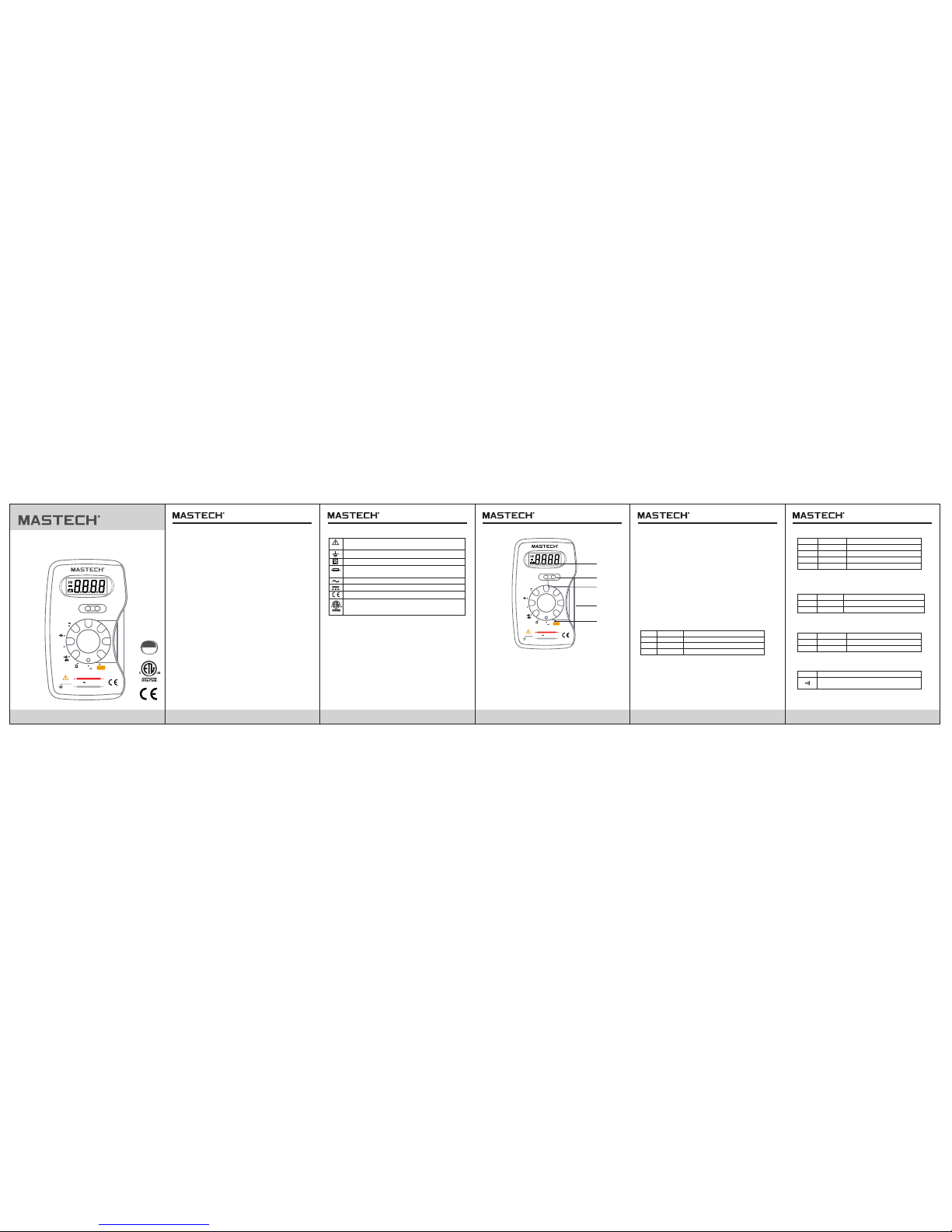
FRO NT PANE L
02
Gene ral Des cript ion
This co mpact d igita l multi meter i s desig ned to me asure
AC and DC Vo ltage s, AC and DC c urren t, Resi stanc e,
Diod e and to pe rform a udibl e Conti nuity c hecks w ith
accu racy an d ease.
Smal l and lig htwei ght, wi th a carr ying ca se and te st lead s
woun d on its Bo dy, this in strum ent wil l provi de you ye ars
of sat isfac tory se rvice .
Auto po wer-o ff funct ion ext ends th e batte ry life . If no
key- input s happe n aroun d 30 minu tes, th is mete r will be
turn ed off aut omati cally.
1. Sele ct Butt on
Mome ntary -type p ush
swit ch for me asuri ng
func tions s elect .
2. HOLD B utton
Mome ntary -type p ush
swit ch for da ta hold .
3. Func tion Sw itch
Rota ry swit ch for
sele cting f uncti ons.
03
M320C
AUTO RANGING
POCKET-SIZED DIGITAL MULTIMETER
OPERATOR'S INSTRUCTION MANUAL
Main tenan ce
• Befo re open ing cas e, alwa ys disc onnec t test be ads
from a ll ener gized c ircui ts.
• For co ntinu ous pro tecti on agai nst fir e, repl ace fus e only
with r ating s; F 400m A/300 V (Quick Ac ting) .
• Neve r use the m eter un less th e back co ver is in p lace
and fa stene d compl etely.
• Do not u se abra sives o r solve nts on th e meter. To cle an
it use s only a da mp clot h and mil d deter gent.
Safe ty Symb ols
05
Spec ifcat ion
Accu racy is g uaran teed fo r 1 year,
23°C ±5°C, less th an 75% RH .
DC Volt age
AC Volt age
Overlo ad protec tion: 300 V DC or rms AC for al l ranges
Input Im pedance :10MΩ
Freque ncy range : 50Hz to 400 Hz, 50 to 60H z for 300V
range.
Respon se: Average r espondi ng, calib rated in rm s of
a sine wav e
DC Cur rent
Overload Protection: F 400mA/300V fuse
Overload protection: 300V DC or rms AC for all ranges
Input Impedance: 10MΩ
Accuracy
±0.8% of rdg ±4 dgts
±0.8% of rdg ±4 dgts
±0.8% of rdg ±4 dgts
Range
4V
40V
300V
Resolution
1mV
10mV
1V
Range Accuracy
Resolution
40mA
±2.0% of rdg ±3dgts
0.01mA
400mA
±2.0% of rdg ±3dgts
0.1mA
Range Accuracy
Resolution
400mV
±0.5% of rdg ± 3dgt
0.1mV
4V
40V
±0.5% of rdg ± 3dgt
±0.8% of rdg ±3dgt
1mV
10mV
300V
1V
±0.8% of rdg ±3dgt
AUTO-RANGE
DMM
300V 400mA MA X
CAT III 300V
M320C
HOLD SELECT
OFF
mA
V
Hz
5
1
4
3
2
AUTO-RANGE
DMM
300V 400m A MAX
CAT III 300V
M320C
HOLD SELECT
OFF
mA
V
Hz
AC Cur rent
Over load Pr otect ion: F 40 0mA/3 00V fus e.
Range Accuracy
Resolution
40mA
±3.0% of rdg ± 4dgts
0.01mA
400mA
±3.0% of rdg ± 4dgts
0.1mA
Audible Continuity Test
Built-in bu zzer sounds whe n resistance
is less than 50 ±20Ω.
Overload Pr otection:25 0V rms ac
Range
Description
4. Test Lead s
Red te st lead f or
posi tive (+ ) and
blac k test le ad for
nega tive (- )
5. LCD Di splay
3 ¾ digi ts, 7 seg ment,
maxi mum 399 9 count s.
Saf ety info rmati on
This m eter ha s been de signe d accor ding to E N6101 0-1,
EN61 010-2 -030, EN610 10-2- 033, 30 0V CAT III an d
poll ution 2.
Foll ow all sa fety an d opera ting in struc tions t o ensur e the
mete r is used s afely a nd is kep t in good c ondit ion Wit h
prop er use an d care, y our dig ital mu ltime ter wil l give yo u
year s of sati sfact ory ser vice.
Dur ing use
• Neve r excee d the pro tecti on limi t indic ated in t he
spec ifica tions f or each r ange of m easur ement .
• Neve r use the m eter to m easur e volta ges tha t might
exce ed 300V a bove ea rth gro und in ca tegor y III
inst allat ions
• Alway s be care ful whe n worki ng with v oltag es abov e
60v dc o r 30v ac rm s. keep f inger s behin d the pro be
barr iers wh ile mea surin g.
• Do not p erfor m resis tance m easur ement s on live c ircui ts.
• Insp ect tes t leads a nd prob es for cr acks, b reaks o r
craz es in the i nsula tion be fore us ing the m eter
• If the eq uipme nt is use d in a mann er not sp ecifi ed by
manuf actur er, the pr otect ion pro vided b y equi pment ma y
be impa ired .
Impo rtant s afety i nform ation , refer t o the
inst ructi on manu al.
Fuse m ust be re place d with ra tings s pecif ied
in the m anual .
AC (Alt ernat ing Cur rent)
DC (Dir ect Cur rent)
Earth(ground) TERMINAL
Equipment protected throughout by double insulation.
CAT III: Applicable to test and measuring circuits connected
to the distribution part of the building's low-voltage MAINS
installation.Example:fixed equipment switchboards,circuit
breakers,wiring,including cables,bus bars,junction boxes,
switches,sockets,utput terminals on devices for industrial
use and other equipment.
CAT III
300V
European union directives
CONFORMS TO UL STD. 61010-1, 61010-2-030,
61010-2-033, 61010-031; CERTIFIED TO CSA STD.
C22.2 No.61010-1,61010-2-030, 61010-2-033,
61010-031.
Page 2
R-0 0-05- 1659
06
08
Resi stanc e
General Characteristics
DC Cur rent Me asure ment
1. Set t he func tion sw itch at m A positi on. And pu sh SELE CT
butto n for DC.
2. Open t he circ uit in wh ich the c urren t is to be me asure d, and
conne ct Test lea ds in ser ies wit h the cir cuit.
3. Read c urren t value o n the LCD d ispla y along w ith the p olari ty
of red le ad conn ectio n.
Maxi mum Ope n Circu it Volta ge:0. 65V
Over load Pr otect ion: 25 0V rms ac f or all ra nges
Range Accuracy
Resolution
400Ω
±1.0% of rdg ±3dgts
0.1Ω
4kΩ
1Ω
40kΩ
10Ω
400kΩ 0.1kΩ
4MΩ 1kΩ
40MΩ
±2.0% of rdg ±4dgts
10kΩ
±1.0% of rdg ±3dgts
±1.0% of rdg ±3dgts
±1.0% of rdg ±3dgts
±1.0% of rdg ±3dgts
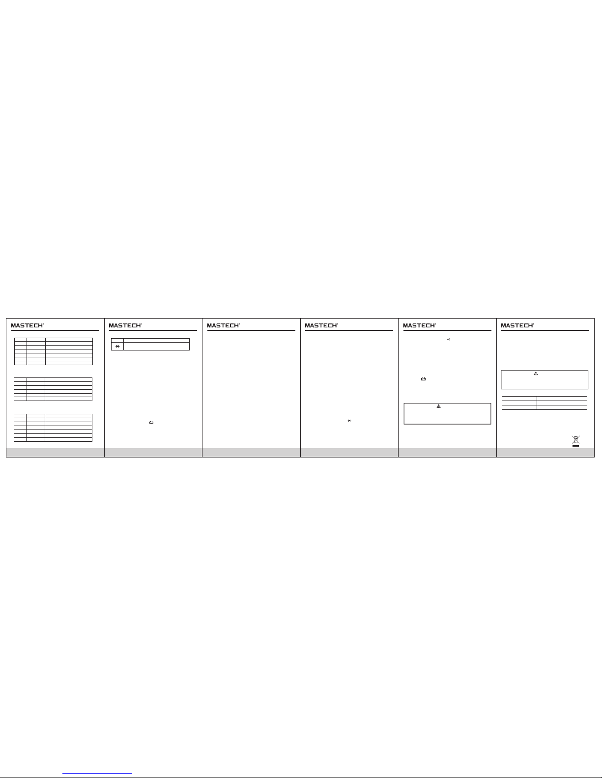
Diod e test
Range
Show t he appr ox.
forw ard vol tage dr op of the d iode.
Overload Pr otection: 250 V rms ac
Description
Range Accuracy
Resolution
10Hz
±0.5% of rdg ±3dgts
0.001Hz
100Hz
0.01Hz
1kHz
0.001kHz
10kHz 0.01kHz
100kHz 0.1kHz
±0.5% of rdg ±3dgts
±0.5% of rdg ±3dgts
±0.5% of rdg ±3dgts
±0.5% of rdg ±3dgts
Freq uency
Overlo ad Prote ction: 30 0V DC or rms AC fo r all range s
Sensit ive: 500 mV RMS
Capa citan ce
Range Accuracy
Resolution
4nF
±5% of rdg ±10 dgts
0.001nF
40nF
400nF
4uF
±4% of rdg ±5d gts
±3% of rdg ±3dgts
±3% of rdg ±3dgts
0.01nF
0.1nF
0.001uF
40uF
0.01uF
±3% of rdg ±3dgts
100uF
0.1uF
±3% of rdg ±3dgts
Overlo ad prote ction: 25 0Vp
Environme nt conditions :
Pollution d egree: 2.
Altitude < 20 00 m.
Operating t emperature:
0~40°C (32° F to 104°F), (<80% R H, non-conden sing)
Storage tem perature:
-10~50°C( 14°F to 122°F), ( <70% RH, batter y removed)
Maximum vol tage between te rminals and eart h
ground:CAT III 30 0V
Fuse Protec tion F 400mA/300 V
Power suppl y 3V battery, SR44 or LR4 4 X 2
Display LCD, 3 999 counts, upd ates 2-3/sec.
Measuring m ethod Dual-slo pe integratio n A/D converter
Over range in dication Figur e”OL” on the disp lay
Polarity in dication “-”di splayed for neg ative polarit y
Operating t emperature 0° Cto 40°C (32°F to 10 4°F)
Storage tem perature -10° C to 50°C (10°F to 122 °F)
Low battery i ndication “
”appears on t he display
Size 120X70X 18mm
Weight Approx.110 g including batt eries
Operating Instruction
DC Volta ge Meas ureme nt
1. Set the func tion switch at V po sition. And push SE LECT
button for DC .
2. Connect te st leads across t he source or load u nder
measureme nt. The Polarity o f red lead connec tion will be
indicated a t the same time as th e Voltage value.
AC Volta ge Meas ureme nt
1. Set the func tion switch at V position . And push SELECT
button for AC.
2. Connect te st leads across t he source or load be ing measured
and read the vo ltage value on th e LCD display.
AC Cur rent Me asure ment
1. Set t he func tion sw itch at m A positi on. And pu sh
SELE CT butto n for AC.
2. Open t he circ uit in wh ich the c urren t is to be me asure d,
and co nnect Test l eads in s eries w ith the c ircui t and
read L CD disp lay.
Resi stanc e Measu remen t
1. Set t he func tion sw itch at Ω p ositi on.
(Not e: The pol arity o f red lea d is posi tive” +”)
2. Conn ect tes t leads a cross t he resi stor to b e measu red
and re ad LCD di splay.
3. If the r esist or bein g measu red is co nnect ed to a cir cuit,
turn o ff power o f the cir cuit an d disch arge al l capac itors
befo re appl ying te st lead s.
4. When m easur ing res istan ce abov e 1MΩ, th e meter w ill
take a f ew seco nds to ge t stabl e readi ng .It is n ormal f or
high r esist ance me asure ment.
Freq uency M easur ement
1. Set th e funct ion swi tch at Hz p ositi on.
2. Conn ect tes t leads a cross t he sour ce or loa d being
meas ured an d read th e frequ ency va lue on th e
LCD di splay.
Capa citan ce Meas ureme nt
1. Set th e funct ion swi tch at Ca pacit ance po sitio n.
2. Conn ect tes t leads a cross t he sour ce or loa d being
meas ured an d read th e capac itanc e value o n the
LCD di splay.
Diod e Test
1. Set t he func tion sw itch at p ositi on.(N ote: The
pola rity of r ed lead i s Posit ive”+ ”)
2. Conn ect the r ed test l ead to th e anode o f the dio de to
be tes ted and t he Blac k lead to t he cath ode of th e diode .
3. The app rox. fo rward v oltag e drop of t he diod e will be
disp layed . If the Co nnect ion is re verse d; only f igure
“OL” will ap pear on t he LCD di splay.
Audi ble Con tinui ty test
1. Set t he func tion sw itch at p ositi on. And pu sh SELE CT
butt on for co ntinu ity
2. Conn ect tes t leads t o two poi nts of th e circu it to
be tes ted.
If the R esist ance is l ess tha n 50±20 Ω, buzz er will s ound.
Data H old Appl icati on
HOLD b utton i s used to h old a mea surin g resul t. When
this b utton i s Pushe d, LCD wi ll keep t he last r eadin g until
push ing thi s butto n again o r rotat ing the f uncti on swit ch.
Batt ery&F use Rep lacem ent
If the s ign app ears on t he LCD di splay, it i ndica tes
that t he batt ery sho uld be re place d. Remo ve the sc rew on
the ba ck cove r and ope n the Cas e. Repl ace the e xhaus ted
batt eries ( SR44 or L R44) wi th same t ypes.
Fuse r arely n eed rep lacem ent and b low alm ost alw ays
as a res ult of Op erato r's err or .Ope n the cas e and rep lace
blow n fuse wi th same r ating s(F40 0mA/3 00V)
Warni ng
Caut ion:
1009
07
Befo re atte mptin g to open t he case , alway s be sure t hat
test l eads ha ve been d iscon necte d from me asure ment
circ uit. Cl ose cas e and tig hten Sc rews co mplet ely bef ore
usin g the met er to avo id elec trica l shock h azard .
For pr otect ion aga inst fi re, rep lace fu se only w ith the
spec ified r ating s: F 400m A/300 V.
Batt ery
Carr ying Ca se
Oper ating m anual
Acce ssori es
4pcs ( Sr44 or L r44)
1pcs
1pcs
WARNING
To avoid electric shock, make sure the probes are
disconnected from the measured circuit before
removing the rear cover. Make sure the rear cover is
tightly screwed before using the instrument.
Usin g this ap plian ce in an en viron ment wi th a stro ng
radi ated ra dio-f reque ncy ele ctrom agnet ic fiel d
(app roxim ately 3 V/m), m ay infl uence i ts meas uring
accu racy. The m easur ing res ult can b e stron gly
devi ating f rom the a ctual v alue.
If the t est lea ds need t o be repl aced, y ou must u se a
new on e which s hould m eet EN 61 010-0 31 stan dard,
rate d CAT III 300 V, 0.4A or bet ter.
WARNING
Repl acing t est lea ds
Repl ace tes t leads i f leads b ecome d amage d or worn .
 Loading...