

Page 1
eMOTION LS Bedienungsanleitung
eMOTION LS User Manual
Wichtige Information zur Inbetriebnahme
Important setup information
Page 2

FREILANDTAUGLICHKEIT
SUITABILITY FOR OUTDOOR USE
Sehr geehrte Kunden, immer wieder erreichen uns Anfragen bezüglich „rostender
Schrauben“ bei Komponenten, die im
Außenbereich der alljährlichen Witterung
ausgesetzt sind. Zweckgemäß führen
Schraubklemmen und Schrauben eine
elektrische Spannung. In Verbindung mit
Feuchtigkeit aus Luft und Boden ndet bei
Anliegen einer Spannung eine elektrochemische Reaktion statt, die physikalischen
Gesetzen unterliegt. Das Auftreten von
sogenanntem Flugrost ist das Resultat und
nicht zu verhindern. Es behindert die Funktion nicht. Sind die Komponenten Wasser
ausgesetzt, beschleunigt dies die Reaktion
deutlich. Wasser muss ungehindert abießen können. Steht die Elektronik im Wasser kann trotz vergossener Elektronik das
Wasser durch die Schraubklemmen ins
innere der Elektronik vordringen und damit
zum Totalausfall führen. Wir möchten Sie
darauf hinweisen, dass die Komponenten
so zu installieren sind, dass sie keiner
andauernden Feuchtigkeit ausgesetzt sind.
Ein Totalausfall auf Grund eines Wasserschadens ist kein Garantiefall.
Dear customer, we have received a
number of enquiries about rusty screws
in components that are used outside and
exposed to the elements. In this regard,
it is important to note that screws and
screw terminals are designed to be able to
carry an electrical current. When they are
exposed to moisture from the air and the
ground, an electrochemical reaction takes
place whenever a difference in electrical
potential is present. This leads to the
formation of a rust lm, which is a natural
physical process that cannot be prevented.
This rust lm does not interfere with
the proper functioning of the component. When components are exposed to
water, the electromechanical reaction is
accelerated considerably. For this reason,
It is important to ensure that water
ows away freely from the components.
Water can seep into components through
screw terminals and soak the enclosed
electronics including those that are potted;
water seepage may lead to total equipment
failure. We would like to point out that
components should be installed in such a
way that they are not exposed to persistent
moisture. Total equipment failure due to
water damage is not covered under the
warranty.
2
Page 3

WICHTIG: Bitte lesen Sie diese
Bedienungsanleitung vor Inbetriebnahme gründlich durch.
IMPORTANT: Please read this
manual thoroughly before installing
or using this product.
HINWEIS: Funktionsausgänge
Die Spannungen der Licht- und Funktionsausgänge sind im Auslieferungszustand auf
volle Spannung eingestellt! Vergewissern
Sie sich VOR dem Anschluss der Lampen
und Funktionsausgänge das die Spannung
entsprechend der CV-Liste richtig eingestellt
ist! Für Schäden durch Nichtbeachtung
dieses Hinweises übernehmen wir keine
Haftung.
Inhaltsverzeichnis
Funktionsumfang.....................................
Lieferumfang............................................
Inbetriebnahme........................................
Einbauhinweise........................................
Motor- und Gleisanschluss......................
Lautsprecheranschluss............................
Erweiterte Einstellungen...........................
Anschlüsse auf der Oberseite...................
Anschlussächen auf der Unterseite........
Einbau......................................................
Einbau in Loks ohne Schnittstelle............
Einbau mit LGB DCC Schnittstelle............
Anschluss an die LGB Dekoderschnittst..
Licht- und Funktionsausgänge.................
Spannungspuffer (BC).............................
Reedkontakte zum Auslösen von Glocke
und Pfeife durch Gleismagnete................
Anschluss SUSI/Massoth-Bus.................
Inbetriebnahme........................................
NOTE: Function outputs:
The function outputs are set per default
to full voltage! Make sure the CVs of the
function outputs are set to the appropriate
value before hooking up any lights or other
accessories. Massoth cannot be responsible
for any damage if this is disregarded.
Table of Contents
Summary of Functions.............................
Scope of Supply.......................................
Hook Up...................................................
Installation Notes....................................
Motor and track connection.....................
Connection of speaker.............................
Advanced settings....................................
Terminals on the upper side....................
Connectors on the lower surface.............
Installation...............................................
Installation without interface....................
Installation with LGB DCC interface.........
Installation with LGB decoder interface....
Light and function outputs.......................
Power buffer (BC)....................................
Reed contacts to trigger bell and
whistle by track magnets.........................
Using the SUSI/Massoth bus...................
Getting started..........................................
5
7
7
7
8
9
10
10
12
14
14
14
15
16
18
19
19
19
3
Page 4

Wichtige Grundeinstellungen...................
Programmierung......................................
Programmierspere CV 15/16...................
Programmieradresse CV 107/108............
Lokadresse...............................................
Anschluss und Funktion...........................
Licht- und Funktionsausgänge.................
Automatischer Entkuppler........................
Servofunktion...........................................
Taktgebersimulation.................................
Kontakteingänge K1/K2............................
Busanschluss...........................................
Analogbetrieb...........................................
Soundfunktionen......................................
Sound- und Funktionszuordnung.............
Fahrgeräusche..........................................
Zusatzgeräusche......................................
Soundverwaltung, Loopanzahl,
Lautstärke................................................
Automatische Geräusche.........................
Anfahrsignal.............................................
Schaltgerhäusche.....................................
Bremsgeräusch........................................
Zufallsgenerator.......................................
Standgeräusche.......................................
Funktionstastenzuordnung.......................
Funktionstaste für Zahnraddampok
oder Zweikraftlok.....................................
Soundzuordnung für Reedkontakt...........
Gesamtlautstärke und Indiv. Lautstärke...
Lautstärkeeinstellung Fahrgeräusche.......
Potentiometer und Lautsprecher..............
Gesamtlautstärke.....................................
Lautstärkeregelung mit Poti.....................
Potiaktivierung im Analogbetrieb.............
Lautsprecherkenndaten............................
Basic factory default settings...................
Programming...........................................
Programming Lock CV 15 / 16.................
Programming Address CV 107 / 108.......
Locomotive address.................................
Connections and functions.......................
Light- and function outputs......................
Automatic Uncoupler...............................
RC Servo function....................................
Pulse generation......................................
Contact Inputs K1/K2...............................
Bus connection........................................
Analog operation......................................
The sound on the decoder.......................
Sound and function assignment..............
Driving sounds.........................................
Additional Sounds....................................
Sound selection, number of loops
and volume..............................................
Automatic sounds....................................
Starting signal..........................................
Operation noises......................................
Braking noise...........................................
Random generator...................................
Standing noises........................................
Funtcion key assignment..........................
Function key for steam rack rail loco
and dual power locos...............................
Sound allocation for reed contacts...........
Total volume and individual volume level.
Volume Control Driving Sounds...............
Loudspeaker + external volume control...
Total Volume............................................
External volume control...........................
External volume control in analog op. .....
Loudspeaker specs..................................
20
21
21
22
22
23
23
23
24
24
24
25
25
26
26
27
28
28
29
29
30
30
31
31
31
32
32
32
33
34
34
34
34
35
4
Page 5

Drehzahlregelung, Steuereingänge
und Steuerausgang..........................................
Resetfunktion...................................................
Programmierung mittels PC und......................
Softwareupdate................................................
CV Tabellen......................................................
Technische Daten.............................................
Garantie, Reparatur, Kundendienst..................
Hotline..............................................................
RPM control, control in-
and outputs...............................................
Reset functions.........................................
Programming via PC and
software update........................................
CV Table....................................................
Technical Data..........................................
Warranty, Service, Support.......................
Hotline......................................................
36
37
37
38
58
58
59
1. Funktionsumfang
• 14, 28 und 128 Fahrstufen
• 256 interne Fahrstufen
• 10239 Lokadressen
• programmierbare Fahrkurve
• Anfahr-, Mittel- und Höchstge-
schwindigkeit (sowie Verzögerungszeiten) einstellbar
• Serielle und parallele Steuerung für
alle Licht- und Funktionsausgänge
incl. LGB® P-Soundupdates
• Digital- und Analogbetrieb mit
automatischer Erkennung
• Kompatibel zu NMRA DCC und
LGB® MZS (alle Generationen)
• Lastregelung neuester Generation
(für Digital- und Analogbetrieb)
• Einstellbare Motorfrequenz
(70Hz - 16kHz)
• 3 Lichtanschlüsse (vorne, hinten,
innen) max. je 0,3 A
• 6 Funktionsausgänge (4 mit je
1. Summary of Functions
• 14, 28 and 128 speed steps
• 256 internal speed steps
• 10239 addresses
• Programmable driving character.
• Adjustable starting speed, medium
speed and maximum speed (with
acceleration/deceleration time)
• Serial and parallel control of all
light and function outputs, incl.
LGB® P-Sound updates
• Digital and analog operation with
automatic recognition
• Compatible with NMRA DCC and
LGB® MTS (all generations)
• Latest technology of load control
(digital and analog)
• Adjustable motor frequency
(70Hz - 16kHz)
• 3 light outputs (front, rear, interior)
max. 0,3 Amps each
• 6 function outputs (4 with 600
5
Page 6

600mA (A1-4), 2 mit je 10mA
(A7+8))
• Licht- und Funktionsausgänge
dimmbar und analog aktivierbar
• Programmierbare Blinklicht-,
Impuls- und Taktgeberfunktion
• 2 zusätzliche Kontakteingänge
• Rangiergang
• einfache Funktionszuordnung für alle
Funktionsausgänge
• alle Funktionsausgänge frei adres-
sierbar (F1 - F16)
• Gesamtbelastbarkeit 2,5 Ampere
(Motorendstufe und Funktionsausgänge)
• Motorendstufe mit 1,5 Ampere
belastbar
• Spannungspufferanschluss für
unterbrechungsfreien Lauf integriert
• Überlast- und Temperaturschutz für
Motor- und Funktionsausgänge
• Resetfunktion für alle CV-Werte
• Firmware updatefähig
• 6-Kanal Soundwiedergabe (bis zu 6
Sounds gleichzeitig)
• 2,4 Watt Class D Verstärker für 8
Ohm Lautsprecher
• Bis zu 200 Sekunden Soundlänge
speicherbar
• 4 Fahrgeräusche und 12 Nebengeräusche abrufbar
• 10kHz bis 16kHz Wiedergabefrequenz
• Taktgeber- und Reedschalteran-
mAmps each (A1-4), 2 with 10mA
each (A7+8))
• Light and function outputs may be
dimmed + activated in analog mode
• Programmable blinking light, shorttime function, and pulse generator
function
• 2 additional contact inputs
• Switching speed
• Easy to use function mapping
• Free command allocation of all
function outputs (F1 - F16)
• Maximum total load 2,5 Amps
(motor and function output)
• 1,5 Amps motor power amplier
• Connector for power buffer (acces-
sory) for smooth running integrated
• Overload and temperature protection
for motor and function outputs
• Reset function for all CV values
• Firmware easy to be updated
• 6 channel play-back (6 sounds at the
same time)
• 2,4 Watt Class D amplier for 8
Ohms loudspeaker
• Memory capacity for max. 200 sec
of recorded sound
• 4 driving sounds and 12 side noises
selectable
• Playback frequency 10 kHz – 16 kHz
• Pulse generator interface and reed
switch terminal
• Volume control by potentiometer or
CV programming (also individual
6
Page 7

schluss
• Lautstärkeregelung per Potentiometer oder CV-Programmierung (auch
Sounds einzeln)
• Soundfunktion auch analog nutzbar
• Sounds und Firmware änderbar
1.1 Lieferumfang
1x eMOTION LS Decoder
1x Anschlusskabel für Beleuchtung
1x Anschlusskabel für Funktion 1+2
1x Bedienungsanleitung
Sounds)
• Sound functions usable in analog
mode
• Sounds and software changeable
1.1 Scope of Supply
1x eMOTION LS Decoder
1x Interface-cable for illumination
1x Interface-cable for function 1+2
1x Manual
2. Inbetriebnahme
2.1 Einbauhinweise
Bauen Sie den Decoder sorgfältig
nach den Anschlussplänen in dieser
Bedienungsanleitung in die Lok
ein. Der Decoder ist generell gegen
Kurzschlüsse oder Überlastung
gesichert. Werden jedoch beim
Einbau Kabel vertauscht oder Kabel
verschiedener Funktionen kurzgeschlossen, kann diese Sicherung
nicht wirken und der Decoder wird
zerstört. Zur Befestigung empfehlen
wir den Platinen- und Decoderhalter
(Art.Nr.: 8104010). Zusätzliche
Kabel für weitere Funktionen nur
mit einem kleinen Lötkolben anlöten
um Kurzschlüsse zu Bauteilen
oder benachbarten Anschlüssen zu
vermeiden. Die Ränder können bei
Bedarf abgebrochen werden.
2. Hook-Up
2.1 Installation Notes
Install your decoder in compliance
with the connecting diagrams in this
manual. The decoder is protected
against shorts and excessive loads.
However, in case of a connection
error e.g. a short between a light
and the motor, this safety feature
cannot work and the decoder will be
destroyed subsequently.
To mount the eMOTION LS use our
decoder bracket (# 8104010)
Use a small soldering iron to prevent
short circuits with other electronic
components or solder pads.
To minimize the size of the decoder
the rims may be snapped off.
7
Page 8
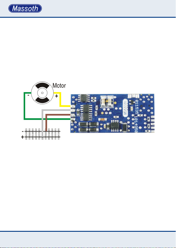
2.2 Motor- und Gleisanschluss
Verbinden Sie das gelbe Kabel mit
Motor (+) und das grüne Kabel mit
Motor (-) am bzw. im Getriebe. Verbinden Sie anschließend das weiße
Kabel mit Gleis (+) und das braune
Kabel mit Gleis (-). Bei LGB ist in
Fahrtrichtung links Gleis (+).
Abbildung 1: Anschluss an Motor + Gleis
Illustration 1: Installation of the eMOTION LS Sound Decoder
Die angegeben Kabelfarben können
vom Aufdruck am Getriebe abweichen! Bei manchen Loks sind die
Getriebe 180° gedreht eingebaut.
Bei anderen Herstellern sind unter
Umständen ganz andere Farben und
Belegungen relevant.
2.2 Motor and track connection
Connect the yellow wire to Motor (+)
and the green wire to Motor (-) at
the gear box. Then connect the white
wire to Track (+) and the brown wire
to Track (-) wire to the track power
leads of the gear box. Track (+) is
left in direction of travel (LGB only)!
The stated wire colores may differ
on the gear box description! Some
locomotives may have gear box
construction with 180° rotation.
Other manufacturers may have different wire colors and connections.
Always read the documentation!
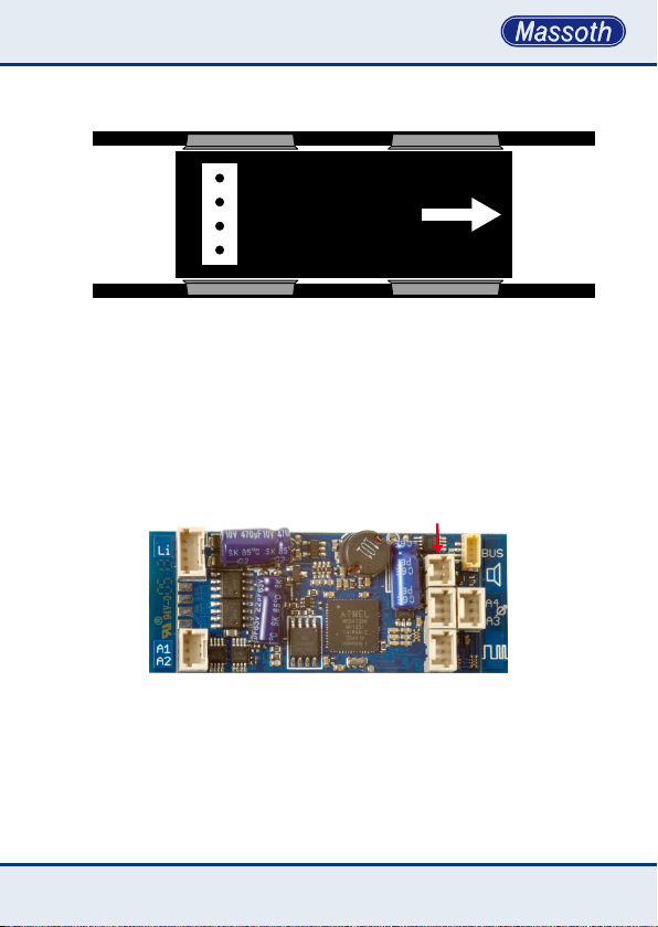
Nachfolgende Abbildung (Abb. 2)
zeigt den korrekten Anschluss an ein
LGB Getriebe.
8
The following illustration shows the
connection to a standard LGB gear
box.
Page 9
Gleis +
ge
ws = Gleis +
br = Gleis gn = Motor -
Abbildung 2: Anschluss an ein LGB Getriebe
Illustration 2: Installation on a LGB gear box
2.3 Lautsprecheranschluss
An die Lautsprecher-Buchse wird
der 8 Ohm Lautsprecher angeschlossen.
Abbildung 3: Anschluss des Lautsprechers
Illustration #3: Connection of loudspeaker
ws
bn
gn
Fahrtrichtungge = Motor +
2.3 Connection of speaker
The 8 Ohm loudspeaker is connected to the Speaker-outlet.
Lautsprecher
Speaker
Gleis -
9
Page 10
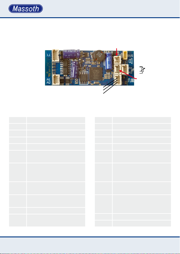
3. Erweiterte Einstellungen
3.1 Anschlüsse auf der Oberseite
LI-V/LI-F
Dec+
LI-I
LI-H/LI-R
Dec-
LI-H/LI-R
LI-V/LI-F
A1
Dec+
A1
A2
Abbildung 4: eMOTION Decoder Anschlüsse
Illustration #4: eMOTION contact assignment
3. Advanced settings
3.1 Terminals on the upper side
Lautsprecher
Dec-
Takt/Clock
+6,5V
Speaker
Taktgeber
Clock
DecRXD
TXD
Dec+
DecPoti
+5V
A4
A3
Dec+
Dec- Masse (-)
Dec+ Gemeinsamer Anschluss (+)
LI-V Licht vorne (-)
LI-H Licht hinten (-)
LI-I Licht innen (-)
Funktionsausgang 1 (-), div.
A1
Blinkfunktionen, Impuls
Funktionsausgang 2 (-), div.
A2
Blinkfunktionen, Impuls,
Wechselblinker
Funktionsausgang 3 (-), div.
A3
Blinkfunktionen, Impuls
Funktionsausgang 4 (-), div.
A4
Blinkfunktionen, Impuls
Poti Anschluss für Potiplatine
Lautspr.
10
Anschluss für Lautsprecher
8Ohm
Dec- GND (-)
Dec+ Common terminal (+)
LI-F front light (-)
LI-R rear light (-)
LI-I interior light (-)
function output 1 (-), some
A1
ashing functions, pulse
function output 2 (-), some
A2
ashing functions, pulse,
alternate ashing
function output 3 (-), some
A3
ashing functions, pulse
function output 4 (-), some
A4
ashing functions, pulse,
alternate ashing
Poti contact for ext. poti
Spkr. contact for speaker 8 Ohm
Page 11

Auf der Oberseite des eMOTION LS
Sounddecoders (Abb. 4) sind sieben
zusätzliche Anschlussbuchsen
vorhanden.
•Taktgeber: Anschluss für einen
externen Taktgeber. Benutzen Sie
hierzu den Taktgeber Nr. 8242030.
•Lautsprecher: Hier wird der 8 Ohm
Lautsprecher angeschlossen.
•Poti: Bei Bedarf kann hier eine
externe Potentiometerplatine Art.Nr.:
8242010 angeschlossen werden.
•A1 / A2 + A3 / A4: Diese Buchsen
sind zum Anschluss der entsprechenden Funktionsausgänge. Max.
Belastbarkeit der Ausgänge 0,6 A.
•Bus-Buchse: Der Busanschluss ist
vorgesehen zur Steuerung weiterer
Komponenten.
• Für den Anschluss an die Funktionsausgänge empfehlen wir die
verschiedenen MiniCT Anschlusska-
bel (8312001, 8312002, 8312003).
Die Belegung können Sie Abbildung
4 entnehmen.
The eMOTION LS Sound Decoder
features seven additional connectors
on the upper side (illustration #4).
•Clock: connector for an external
pulse generator. Please use pulse
generator unit #8242030.
•Speaker: The Speaker connector
connects a loudspeaker (8 Ohm).
•Poti: The Poti connector connects
an external potentiometer for manual
volume control (item # 8242010).
•A1 / A2 + A3 / A4: These sockets are
for connecting the corresponding
function outputs. Each output has a
load capacity of 0.6 amps.
•Bus-connector: The Bus-connector
is provided to control additional
components.
We suggest to use the micro
decoder cables (8312001, 8312002,
8312003) to connect the compon-
ents to the decoder. The connector
assignment is illustrated in g. #4.
11
Page 12
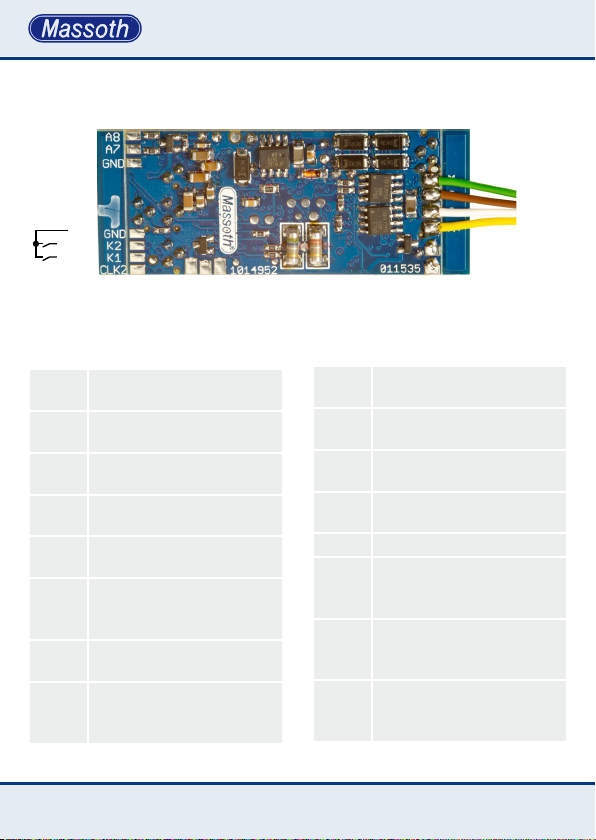
3.2 Anschlussächena.d.Unterseite
A8
A7
Dec-
DecReed 1
Reed 2
CLK2
Abbildung 5: eMOTION Dekoder Anschlüsse unten
Illustration #5: eMOTION contact assignment lower surface
BC
Dec-
Dec+
3.2 Connectors on the lower surface
Motor-
Motor+
Dec+
A2
GleisGleis+
12
Gleis (-) Braunes Kabel zum
GL-
Getriebeanschluss
Gleis (+) Weißes Kabel zum
GL+
Getriebeanschluss
Motor (-) Grünes Kabel zum
MOT-
Getriebeanschluss
Motor (+) Gelbes Kabel zum
MOT+
Getriebeanschluss
Dauerhafter (-) Pol. (Z.B. für
Dec-
einen Pufferanschluss)
Gemeinsamer Anschluss (+) für
Lampen- und
Dec+
Funktionsausgänge
Funktionsausgang 2 (-), div.
A2
Blinkfunktionen, Impuls
Funktionsausgang 7 (+), div.
Blinkfunktionen, Impuls,
A7
Wechselblinker, Servo, 5V
track (-) brown wire to the motor
GL-
block
track (+) white wire to the motor
GL+
block
motor (-) green wire to the
MOT-
motor block
motor (+) yellow wire to the
MOT+
motor block
GND (-) e. g. for a power buffer
Dec-
Common terminal (+)
for light and function
Dec+
outputs
function output 2 (-),
some ashing functions, pulse,
A2
RC
function output 7 (+), some
ashing functions, pulse, alter-
A7
nate ashing, servo, 5V
Page 13

Funktionsausgang 8 (+), div.
A8
Blinkfunktionen, Impuls 5V
Kontakteingang 1,
Reed1
Pendelfunktion
Kontakteingang 2
Reed2
Buffer Control (-)
BC
Anschluß für 2. Taktgeber
CLK2
function output 8 (+), some
A8
ashing functions, pulse, 5V
contact input 1,
Reed1
shuttle operation
contact input 2
Reed2
Buffer Control (-)
BC
Connector for second pulse gen.
CLK2
Auf der Unterseite des eMOTION
LS Sounddecoders sind mehrere
Anschlüsse angebracht.
•Getriebeanschlusskabel: Mit den 4
Getriebeanschlusskabeln verbinden
Sie den LS Decoder mit Motor und
Gleis.
•A2, A7, A8: A2 ist ein alternativer
Lötanschluss zum Stecker oben.
Die Funktionsausgänge A7 und A8
haben eine Belastbarkeit von 10 mA
je Ausgang bei 5V.
•BC (Spannungpuffer): Dies dient
zum Anschluss von eMotion Power-
caps (8151601 und 8151701).
•CLK2: Ist für den Anschluß eines 2
Taktgebers. Die hierfür benötigten
6,5 V muss man sich von dem
Stecker des Taktgebers auf der
Oberseite holen.
•Reed 1 + 2: Dies sind Kontaktein-
gänge um z.B. Glocke oder Pfeife
auszulösen, oder um eine einfache
Pendelfunktion zu realisieren.
Some more contacts are located on
the lower side of the eMOTION LS
Sound Decoder.
•Motor Cables: The LS Sound
Decoder is connected to the motor
block using the four coloured motor
cables.
•A2, A7, A8: A2 is an optional solder
pad to the plug above. The function
outputs A7 and A8 have a capacity
of 10 mA per output at 5V.
•BC (Powercap): These 3 pads are
to connect eMotion Powercaps
(8151601 und 8151701).
•CLK2: A second hall sensor can be
connected here. The required 6.5V
need to be drawn from the socket on
the top side.
•Reed 1 + 2: These contacts can be
used to trigger the bell or whistle
(programmable) or a simple shuttle
function.
13
Page 14
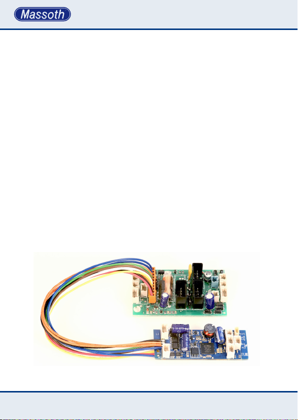
4. Einbau
4.1 Einbau in Loks ohne Schnittstelle
Generell lässt sich der Decoder in
Loks ohne Schnittstelle besonders
einfach einbauen. Dabei wird der
Decoder mit Hilfe der mit gelieferten
Kabel direkt am Getriebe angeschlossen. Der Aufbau des Getriebes
kann abhängig vom Hersteller
unterschiedlich sein.
ACHTUNG: Bei Piko®-G Loks sind
die Motor- und Gleisanschlüsse gegenüber LGB®-Getrieben
vertauscht!
4. Installation
4.1 Installation without interface
Installation in a locomotive without
interface is pretty simple. The decoder must be connected to the 4 leads
of the motor block utilizing the color
coded wires provided. The design of
the motor block may vary with the
manufacturer.
Note: The motor and track connection with PIKO®-G locos is switched
compared to LGB®.
4.2 Einbau mit LGB DCC Schnittstelle
Unter Artikelnummer 8211098 ist
der eMOTION LS Sounddecoder
mit 10-poligem Schnittstellenkabel,
4.2 Installation with LGB DCC Interface
The eMOTION LS Decoder is available
with the 10-pin DCC plug for the LGB
DCC interface under #8211098.
passend für die LGB DCC Schnittstelle erhältlich.
Abbildung 6: eMOTION Dekoder an LGB DCC Schnittstelle
Illustration #6: eMOTION decoder connected to LGB DCC Interface
14
Page 15
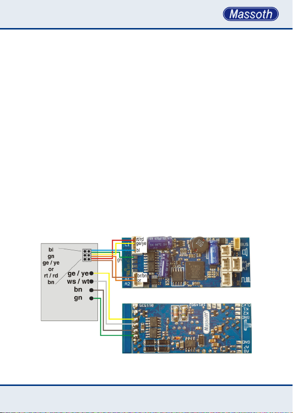
4.3 Anschluss an die LGB
Decoderschnittstelle
Mit dem LGB® Schnittstellenkabel
kann der Decoder zusätzlich an
LGB® Loks mit der Decoderschnittstelle eingebaut werden (Abb.
7). Über dieses Kabel können die
Licht- und Soundfunktionen der
Lok gesteuert werden. Das LGB®
Schnittstellenkabel ist unter der
Artikelnummer 8150602 im Massoth
Sortiment erhältlich. Verbinden Sie
die Anschlüsse an den Steckern mit
den mitgelieferten Kabeln. Achten
Sie darauf das Sie nichts verpolen
oder kurzschließen! Die Getriebekabel und das dünne grüne Kabel löten
Sie Bitte an die entsprechenden
Lötächen.
4.3 Installation with LGB
decoder interface
Using the LGB® decoder interface
cable the eMOTION LS can be easily
installed in LGB® locomotives with
a decoder interface (Illustr. #7). The
light and sound functions will be
handled via this cable. The LGB
interface cable may be purchased
as Massoth® item No. 8150602.
Connect the wires to the eMOTION
LS terminals according to the wiring
diagram. Mind the polarity! Do not
mix-up the wires or short any wires!
Solder the gear box wires and the
thin green wire to the respective
soldering pads.
®
Abbildung 7: Einbau in Lok mit LGB Decoder Schnittstelle
Illustration #7: Installation in a Loco with LGB Decoder Interface
15
Page 16

4.4 Licht und Funktionsausgänge
Der eMOTION LS verfügt über
verschiedene Licht- und Funkti-
onsausgänge. Es benden sich 3
Lichtanschlüsse auf dem Decoder.
Dabei handelt es sich um Frontlicht, Rücklicht und zusätzlich die
Innenbeleuchtung. Die Front- und
Rückbeleuchtung werden fahrtrichtungsabhängig geschaltet. Die
Innenbeleuchtung ist dauerhaft an,
wenn die Beleuchtung eingeschaltet
ist. Nutzen Sie diese Funktion um
den Innenraum Ihrer Lokomotive
oder das Getriebe bzw. Gestänge
Ihrer Dampok zu beleuchten,
oder um z.B. die typische Rückbeleuchtung der RhB Lokomotiven zu
realisieren. Denn diese Leuchten
brennen immer. (Gesamtstromver-
brauch der angeschlossenen Lampen max. 300mA je Anschluss).
Der eMOTION LS Sounddecoder
verfügt zudem über 6 separate
Funktionsausgänge, die unterschiedlich genutzt werden können. Auf der
Oberseite benden sich 4 Funktionsausgänge auf zwei Buchsen, 2
weitere benden sich als Lötkontakt
auf der Unterseite des Decoders
(A7, A8). Alle Licht- und Funktions-
ausgänge A1-A4 des eMOTION LS
Sounddecoders sind bei der Auslieferung auf maximale Ausgangs-
4.4 Light and function outputs
The eMOTION LS Sound Decoder
features 3 light outputs, front light,
rear light, and interior light. The
front light and rear light are switched
according to the driving direction,
the front light output is “on” when
driving forward, and the rear light
is illuminated when driving in
reverse. The interior light is steadily
“on” when the lights are switched
“on”. You may use this function to
illuminate the interior of the cab of
your locomotive or to illuminate the
connecting rods of a steam locomotive or to implement the typical rear
light of RhB locomotives because
these lights are always “on”. (The
limit is 300 mAmps per output). The
eMOTION LS Sound Decoder features
6 additonal function outputs which
may be used in different ways. Four
outputs are located on the upper side
on a jack and two on the rear side as
solderable contact. The factory setting of the light and function outputs
A1-A4 gives full track voltage to them
(adjustable in CV 50, 53, 112).
The voltage supplied by the outputs
7+8 is 5Volts, and the maximum
allowable load is 10 mAmps. The
function (e.g. F-key assignment, light
display according to driving direction,
ashing and short term function) as
16
Page 17
spannung eingestellt (einstellbar in
CV 50, 53, 112). Die Ausgänge 7+8
haben nur eine Spannung von 5 Volt
und dürfen mit max. 10 mA belastet
werden. Funktionen der einzelnen
Licht- und Funktionsausgänge
können über die Programmierung
eingestellt werden. Die Lichtausgänge sowie die Funktionsausgänge
A1-A4 sind dimmbar.
ACHTUNG: Die Lichtfunktion ist abhängig
von der gewählten Fahrstufenanzahl. Ist die
Einstellung (CV 29) nicht mit der Einstellung
des Digitalsystems identisch, blinkt das Licht
oder ist immer aus. (Bei 128 Fahrstufen ist
dies jedoch nicht relevant)
well as the voltage of output A1-A4
may be programmed by setting the
respective CV’s. For details please
review the CV-table. The outputs
may be controlled by NMRA/DCC
commands or with serial LGB® pulse
strings. The light outputs and the
outputs A1 to A4 are dimmable.
NOTE: The proper operation of the light
functions depends on the selected speed
steps. In case CV 29 (speed steps) does not
carry the same setting as the digital system
the lights may icker or might not work at all
(not relevant for 128 speed steps)
Dec+
max. 300mA
gesamt/total
Dec+
je 600mA (each)
R=470R
je 10mA (each)
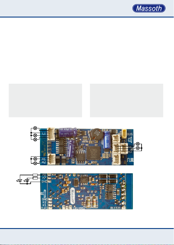
Abbildung 8: Licht und Funktionsausgänge und deren Verschaltung
Illustration #8: Connection scheme of the light and function outputs
Dec-
je 600mA (each)
Dec+
17
Page 18
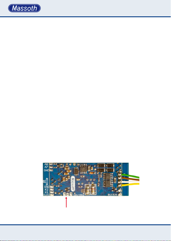
4.5 Spannungspuffer (BC)
Der eMOTION LS besitzt einen
3-poligen Lötanschluss für Spannungspuffer (8151601 + 8151701).
Massoth Powercaps besitzen
eine zusätzliche Steuerleitung, die
Störungen beim Einschalten oder
Programmieren verhindert. Der
Anschluss erfolgt an „DEC+“ (rt),
„DEC-“ (sw) und wenn vorhanden,
die Steuerleitung an „BC“ (ws).
Die Stromaufnahme beim Laden darf
höchstens 500mA betragen. Der
Puffer arbeitet im Digital/Analogbetrieb gleichermaßen. Im Analogbetrieb arbeitet der Puffer vollautomatisch und schaltet im Stand nach
den Standgeräuschen den Decoder
ab. Für den Digitalbetrieb sollte der
Analogbetrieb gesperrt werden (CV
29 Bit 2). Die Nachlaufzeit der Lok
kann man im Digitalbetrieb mit CV
129 steuern, im Analogbetrieb mit
CV 130.
4.5 Power buffer (BC)
The eMOTION LS features a separate
connector for power buffers
(Massoth 8151601 + 8151701).
The power buffer bridges brief power
interruptions caused by contaminated tracks or bad power supply on
switches. The power buffer is to be
connected to the connectors marked
“DEC+“ (red), “DEC-“ (black) und
“BC“ (white) on the decoder board.
The maximum charging Amperage is
500mAmps. The power buffer works
in analog as well as in digital operation. In analog operation the power
buffer works fully automatic. After the
locomotive has stopped, the power
buffer switches off the decoder after
the standing noises were released.
The buffer runtime can be adjusted
in CV 129 (digital operation) and CV
130 (analog operation).
BC
Dec-
Dec+
Abbildung 9: Anschluss eines Spannungspuffers
Illustration 9: Connection of a Power Buffer
1818
Page 19

4.6 Reedkontakte zum Auslösen von
Glocke und Pfeife durch Gleismagnete
Möchten Sie die Auslösung eines
Sounds durch Gleismagnete nutzen,
so können bis zu zwei Reedkontakte
(potentialfrei) über die Reedkontaktanschlüsse des eMOTION LS Sounddecoders gegen GND angeschlossen
werden (Abb. 5). In der CV-Konguration (CV 190, 191) legen Sie fest,
welche Geräusche beim Schalten
der Reedkontakte ausgelöst werden
sollen. Eine besondere Funktion ist
die richtungsabhängige Auslösung
der zugewiesenen Geräusche bei
Vorwärts- und Rückwärtsfahrt
(aktivierbar in CV 149, Bit 4).
4.6 Reed contacts to trigger bell and
whistle by track magnets
You may utilize up to two reed
contacts to trigger sounds with track
magnets. The CV conguration (see
Conguration Manual) denes which
sound is to be triggered by which
reed contact. (Illustr. #5)
With the CV conguration (CV 190,
192) you may assign which sounds
will be played when the reed contacts
are triggered.
A special feature is the possibility
to trigger a sound depending on the
driving direction
4.7 Anschluss SUSI/Massoth-Bus
An diesen 4 poligen SUSI Stecker
kann z.B. ein gepulster Verdampfer
oder Soundmodule nach SUSI-Norm
angeschlossen werden.
5. Inbetriebnahme
Das Konzept des eMOTION LS legt
großen Wert auf einfache Einbau- und Anschlussmöglichkeiten,
daher wird er mit abbrechbarer,
beschrifteter Leiste ausgeliefert. Er
ist bereits mit passenden Anschlusskabeln ausgestattet, so dass
am Decoder kaum etwas gemacht
4.7 Using the SUSI/Massoth bus
This 4-pole terminal may be used
for e.g. pulsed smoke generators or
sound modules in compliance with
the SUSI norm.
5. Getting started
eMOTION LS Decoders are designed
for easy handling and installation. To
make them t into most of all types
of locomotives most of the Massoth
eMOTION decoders may be reduced
in size by detaching parts of the
decoder, e.g. mounting holes or the
ledges that carry the labeling of the
1919
Page 20

werden muss.
terminals. The small decoders come
pre-wired. Soldering is not required.
5.1 Wichtige Grundeinstellungen
Die Grundeinstellungen des
eMOTION LS Decoders sind wie
folgt:
Grundeinstellung der SoundDecoder (LS)
Lokadresse 3
Spannung Funktionen 22 Volt (max. Spannung)
5V (A7+8)
Funktionsausgang A1 Funktionstaste: F1
Funktionsausgang A2 Funktionstaste: F2
Funktionsausgang A3 Funktionstaste: F3
Funktionsausgang A4 Funktionstaste: F4
Funktionsausgang A7 Funktionstaste: F19
Funktionsausgang A8 Funktionstaste: F14
Funktionsauslösung nur parallel
Bei Verwendung eines LGB® MZS I
oder II Digitalsystems (ohne parallele Funktionsauslösung) muss die
serielle Funktionsauslösung mit CV
49 - Bit 0=1 aktiviert werden.
5.1 Basic factory default settings
This table shows the basic factory
default settings of the eMOTION S:
Basic settings sound decoder (S)
Locomotive address 3
Function voltages 22 Volt (full track power)
5V (A7+8)
Function output A1 Function key: F1
Function output A2 Function key: F2
Function output A3 Function key: F3
Function output A4 Function key: F4
Function output A7 Function key: F19
Function output A8 Function key: F14
function triggering parallel only
Using the LGB® MTS I or MTS
II digital system (no parallel data
processing) CV 49 - Bit 0=1 must
be activated for serial function
triggering.
20
Page 21
5.2 Programmierung
Es gibt einige CVs, die besonders
wichtig sind, und richtig eingestellt
sein sollten, damit ein einwandfreier
Betrieb sichergestellt ist.
WICHTIGER HINWEIS
ZUR PROGRAMMIERUNG
Für die Programmierung muss der
Decoder an einen Motor angeschlossen sein. Ein kurzes Zucken am Motor
quittiert dabei den Programmierprozess.
5.2 Programming
There are CVs that are of particular
importance to ensure a awless
operation.
IMPORTANT NOTE FOR
PROGRAMMING
All CVs may be programmed if the
eMOTION LS decoder is connected to
a motor. A brief twitch of the motor
acknowledges the programming
process.
5.3 Programmiersperre CV 15 / 16
Um ein versehentliches Programmieren zu verhindern ist in CV 15
und 16 eine Programmiersperre
realisiert. Nur wenn CV 15 = CV
16 entspricht, kann man CV Werte
verändern. Ist CV 15 ≠ CV 16, ist die
Programmiersperre aktiv. Der Wert
in CV 16 sollte nicht geändert werden. So ist es jederzeit möglich CV
Werte auch im eingebauten Zustand
mit anderen Decodern zu ändern.
Standardwert CV 15/ CV 16 = 144.
Sollte die Programmiersperre aktiv
sein und Sie wissen den Wert von
CV 16 nicht mehr, so können Sie
mit CV 7 = 55 den Decoder auf die
Grundwerte zurücksetzen.
Nach erfolgreicher Einstellung
Ihres Decoders unbedingt die
Programmiersperre setzen!
5.3 Programming Lock CV 15 / 16
To prevent unintentional programming this sounddecoder offer a
programming lock in CV 15 / 16. If
CV 15 matches CV 16 programming
is possible. If CV 15 ≠ CV 16 the
programming lock is active. We recommend to not change the value of
CV 16. This allows to alter CV values
anytime even when the decoder is
installed with other decoders. The
standard value of CV 15 / 16 = 144.
If the programming lock is active
and you do not remember the value
of CV 16, you may reset the decoder
with CV 7 = 55 to its factory default
settings.
After programming the decoder it is
absolutely recommended to activate
the programming lock.
21
Page 22

5.4 Programmieradresse CV 107 / 108
Diese Adresse wird benötigt um
den Decoder später im eingebauten
Zustand (mit weiteren Decodern)
programmieren zu können. Die Programmieradresse muss im Bereich
von 128-10239 liegen! Sie darf nicht
identisch mit der Lokadresse sein.
Die Berechnung ist identisch zu CV
17 / CV 18. Der Standardwert ist
Adresse 10239.
5.4 Programming Address CV 107 / 108
The programming address is used to
programm the decoder after installation (when other decoders are installed). The value span ranges from
128-10239! It may not be indentical
to the locomotive address. Address
calculation is identical to CV CV 17 /
18. The standard value is 10239.
5.5 Lokadresse
Wird der eMOTION LS Decoder in
Verbindung mit anderen Decodern
verwendet, muss die Programmierung der Adresse vorab erfolgen.
Eine komfortable Programmierung
der Lokadresse samt aller notwändigen CV‘s ist mit dem DiMAX
Navigator möglich.
Man unterscheidet wie folgt:
• kurze Lokadresse 1...127 in CV 1,
beachten Sie CV 29 / BIT5 = ‚aus‘
• lange Lokadresse 128...10239
in CV 17 / CV 18, zusätzlich muss in
diesem Fall CV 29 / BIT 5 = ‚an‘ sein.
Man berechnet wie folgt:
CV 17 = Adresse / 256
(nur der ganzzahlige Wert)
CV 18 = Adresse – (CV 17 x 256)
• Mehrfachtraktionsadresse
(1...99 in CV 19)
22
5.5 Locomotive address
In case the eMOTION LS Decoder is
used in connection with third party
decoders, the address must be programmed separately. A comfortable
way of programming including all
affected CVs can be performed with
the DiMAX Navigator.
A distinction is drawn between:
• short addresses (1...127) in CV 1
(CV 29 - Bit 5 has to be deactivated)
• long addresses (128...10239)
in CV 17 / 18, plus CV 29 - Bit 5
needs to be activated. The long
address is calculated as follows:
CV 17 = address / 256
(only the whole-number value)
CV 18 = address – (CV 17 x 256)
• Multiple Unit addresses
(1…99 in CV 19)
Page 23
6. Anschluss und Funktion
6.1 Licht- und Funktionsausgänge
Die Licht- und Funktionsausgänge
können frei programmiert werden.
(Zuordnung der Funktionstaste,
Richtungsabhängigkeit, Blink- und
Impulsfunktionen, Taktgeber).
Die Ausgänge können mit NMRA/
DCC-Befehlen oder mit serieller
LGB®-Pulskette gesteuert werden.
Ausgang A1-A4 kann mit verschiedenen Zeitfunktionen programmiert
werden. Die Ausgänge A1-A4 sowie
Licht sind OpenCollector-Funktionsausgänge.
6. Connections and Functions
6.1 Light- and function outputs
The light- and function outputs are
freely programmable (key assign-
ment, directionality, ashing and
short term function, sound pulse
generator). The outputs may be con-
trolled with NMRA/DCC commands
or serial pulse strings. The outputs
A1-A4 may be programmed for
ashing operation (symmetric and
asymmetric ashing, timer function).
The outputs A1-A4 as well as light
are open collector outputs.
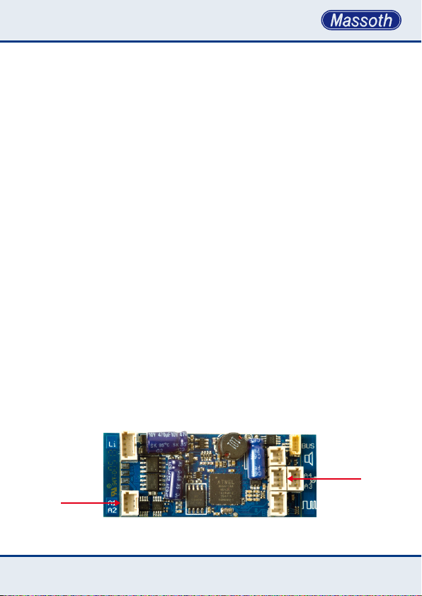
6.2 Automatischer Entkuppler
Die Funktionsausgänge A1/A2 und
A3/A4 sind direkt für den Anschluss
des Automatischen Entkupplers
(8414002) vorbereitet. Der Entkuppler wird direkt in die Anschlussbuche
gesteckt, zusätzlich muss wie folgt
programmiert werden:
• A2: CV 56 auf Wert 31 (immer an)
• A4: CV 115 auf Wert 31 (immer an)
Entkuppler
Uncoupler
Abbildung 10: Anschlüsse für Automatische Entkuppler am eMOTION LS
Illustration #10: Connections for Automatic Uncoupler on the eMOTION LS
6.2 Automatic Uncoupler
The function outputs A1/A2 and A3/
A4 can be congured to operate the
Automatic Uncoupler (8414002). The
Uncoupler is connected directly to
the sockets. Additionally the following CVs need to be programmed as
listed here:
• A2: CV 56 with value 31 (always on)
• A4: CV 115 with value 31 (always on)
Entkuppler
Uncoupler
23
Page 24

6.3 Servofunktion
Ausgang 7 kann zur Steuerung eines
Servos genutzt werden. In CV 124
wird die Sondernutzung aktiviert. Mit
CV 125 + 126 wird der Drehbereich
festgelegt. In CV 127 kann die
Drehgeschwindigkeit beeinusst
werden. Zur Spannungsversorgung
des Servos nutzen Sie unseren 6V
Festspannungsregler (8242050).
6.3 RC Servo function
Output 7 may be utilized to control an
RC servo. This function is activated
with CV 124. CV 125 and CV 126 dene the turning range. In CV 127 the
servo speed is set. For servo power
supply we suggest to use our 6V
Fixed Voltage Regulator (8242050).
6.4 Taktgebersimulation
Ausgang 3 kann als Drehzahlsimulator für z.B. einen gepulsten Verdampfer genutzt werden. Mit CV 114
= 30 wird diese Funktion aktiviert.
Der Ausgang arbeitet einfach als sogenannter „Open-Collector-Schalter“
gegen GND.
6.5 Kontakteingänge K1/K2
Zum Auslösen von Geräuschen
(Pfeife / Glocke) kann zwischen K1
oder K2 und GND ein Reedkontakt
geschaltet werden. Die Zuweisung
erfolgt in CV 190 / 191.
24
6.4 Pulse generation
Function output 3 may be used for
pulse generation for a pulsed smoke
unit or an external sound module.
The function is activated with CV 114
= 30. The output is an open-collector
circuit switching to GND.
6.5 Contact Inputs K1/K2
Reed contacts may be connected to
K1/ K2 and GND to trigger additional
sounds (e.g. whistle and bell). The
sound assignment is programmed in
CV 190 and 191.
Page 25

6.6 Busanschluss (CV 49)
•Massoth/LGB-Bus
Über den Massoth Bus bekommt der
LS Decoder folgende Informationen:
Anfahren, Anhalten und Lastzustand.
•SUSI-Bus
Über den SUSI-Bus bekommt der
eMOTION LS Decoder folgende
Informationen: Lok-Fahrstufe,
Lastausregelung, CV lesen/schreiben
und PoM.
6.6 Bus Connection
•Massoth/LGB bus
The Massoth bus provides the
following information: Acceleration,
stopping, load condition.
•SUSI bus
The SUSI bus provides the following
information: Speedstep, load condition, CV programming, POM.
7. Analogbetrieb
Der Analogbetrieb ist bei Auslieferung gestattet. (Analogbetrieb
sperren mit CV 29 Bit 2, wichtig bei
Anschluss eines Spannungspuffers).
Die Lichtausgänge sind immer
richtungsabhängig an. Funktions-
ausgänge können (CV 13) analog
aktiviert werden. Einstellungen
(Blinken, Dimmen, etc.) sind auch
analog nutzbar.
7. Analog operation
The analog operation may be blocked
with CV 29 bit 2 (for buffer operation). The factory default setting allows
the analog operation. The light outputs are constantly on and working
dependent of the driving direction.
The function outputs may be activated separately for analog operation
in CV 13. Settings for ashing and
dimming work as well.
25
Page 26

8. Soundfunktionen
Der eMOTION LS Sounddecoder gibt
den Funktionsumfang einer Lokomotive in hoher Qualität realistisch wieder. Dabei beschränkt sich der eMOTION LS Decoder nicht rein auf die
typischen Fahrgeräusche, sondern
bietet zudem eine große Auswahl an
Zusatzsounds, die wahlweise genutzt
werden können. Damit kann jede
Lok individuell abgestimmt werden.
Der eMOTION LS Decoder verarbei-
tet bis zu 16 Soundfunktionen. Die
abgelegten Sounds im Speicher des
Sounddecoders werden dabei über
die Programmierung den einzelnen
Funktionen und Funktionsbefehlen
zugeordnet. Abhängig vom entsprechenden Vorbild und den abgelegten
Sounds unterscheiden sich die
CV-Einstellungen der Sounddecoder
voneinander.
8. The Sound in the decoder
The eMOTION Sound Decoder
contains a full edged digital
power amplier which reproduces
all sounds and side noises of a
locomotive in high quality and very
realistically. The eMOTION Sound
Decoder produces a locomotive’s
prototypical operating sound as
well as an array of additional sounds
which may be utilized according to
your taste and needs. This allows
you to individualize locomotives of
the same type. The eMOTION Sound
Decoder manages up to 16 sound
functions. The memorized sounds are
assigned to functions and function
commands by CV programming. The
CV settings of the eMOTION Sound
Decoder may vary depending on the
original locomotive and the sounds
stored in the memory.
8.1 Sound- und Funktionszuordnung
Der eMOTION LS Sounddecoder ist
in der Regel nach einem gleichmäßigen Muster eingerichtet. Das heißt,
unabhängig vom Soundprojekt sind
die Funktionen grundlegend gleich
zugeordnet. Über die Grundbelegung hinaus, verfügt jeder Sound
Decoder über Geräusche, die jeweils
individuell zugeordnet sind. (siehe
Decoderdatenblatt). Jeder eMOTION
26
8.1 Sound and function assignment
Each locomotive displays certain
sounds and side-noises which are
characteristic for the respective type
of engine. In addition to the basic
sounds each eMOTION LS Decoder
carries sounds and side-noises which
are individually assigned and therefore can not be listed in this table.
Each eMOTION LS Decoder carries
up to 16 sounds and side-noises
Page 27

LS Soundecoder verfügt über bis
zu 12 Geräusche, die einzelnen
Funktionstasten zugeordnet sind.
Neben diesen Geräuschen sind auch
Funktionen, wie z.B. das Ausschalten
des Verstärkers, der Rangiergang
oder das Ausschalten der Verzögerungszeiten zugeordnet. Die
Geräusche und Funktionen können
den 16 möglichen Funktionstasten
per CV-Programmierung zugeordnet werden. Sounds können auch
komplett abgeschaltet werden.
Informationen zum Programmieren
der Soundzuordnung entnehmen
Sie bitte den CV-Tabellen und den
dazugehörigen Anhängen.
WICHTIG: Möchten Sie Funktionsta-
sten größer als F12 zuordnen, muss
CV 49=Bit 0 auf Wert 0 gesetzt sein
(nur parallele Funktionsdatenverarbeitung)!
which are assigned to the F-keys. Besides the sounds other functions are
assigned, e.g. sound on/off, accel./
deceleration on/off, switching speed
on/off. The sounds and the functions
may be assigned to the 16 F-keys
by CV-programming. You may alter
the F-key assignment at any time
according to your personal needs and
move for example the braking sounds
from F3 to F12. Or sounds may be
switched off completely. In-depth
information can be found in the CVTables as well as in the correspondi-
ng attachments, starting at page 38.
Important: In case the F-key
assignment is greater than F12,
CV 49 = Bit 0 must be set to “0“
(only parallel data processing)
8.2 Fahrgeräusche
Die Fahrgeräusche der 3 Loktypen,
Dampf-, Diesel- und E-Lok sind
unterschiedlich und gliedern sich
üblicherweise in vier Bereiche:
• Aufrüsten
• Standgeräusche
• Fahrgeräusche
• Abrüsten
Dabei zeigt jede Phase die spezi-
schen Geräusche des Vorbilds.
8.2 Driving sounds
The driving sound vary with the
locomotive type: steam, diesel, or
electric which are typically ordered in
four parts as follows:
• Start up
• Standing noises
• Driving sounds
• Shut down
Each phase shows the situation
specic sound from the original pro-
27
Page 28

Da es viele Unterschiede bei den
Vorbilder gibt, variiert der Funktionsumfang des Sounddecoders teilweise
deutlich. Details entnehmen Sie bitte
dem Soundprojekt zugeordneten
Sounddatenblatt.
totype. The functionality of the sound
decoder may vary signicantly due to
the wide range of original prototype
features. For details please see the
sound project associated sound data
sheet.
8.3 Zusatzgeräusche
8.3.1. Soundverwaltung, Loopanzahl
(Dauerloop) und Lautstärke
Mittels Funktionstaste lassen sich
Betriebsgeräusche der Lok, wie
Pfeifsignal, Generator, Kompressor
oder auch Ansagen abrufen.
Die Zuordnung geschieht in den
sogenannten CV‘s (Conguration
Variablen, Kongurations Variablen).
Dem Pfeifsignal, Sound Nummer 1,
sind die CV‘s 131, 151 und 201 zugeordnet. Dem Pfeifsignal mit Echo,
Sound Nummer 2, sind die CV‘s 132,
152 und 202 zugeordnet, usw.
In der ersten CV ist die Funktionstaste, mit der das Geräusch geschaltet
wird, eingetragen, in diesem Fall eine
1, also Funktionstaste 1.
In CV 151 wird die Anzahl der Wiederholungen eingetragen. Bei 1 wird
eine Wiederholung ausgeführt, bei
2 gleich 2 usw. Bis zu 15 Wiederholungen können programmiert werden.
Wird eine 16 eingetragen, wird
eine Dauerschleife geschaltet, das
heißt, mit schalten der zugeordneten
8.3 Additional sounds
8.3.1. Sound selection, number of
loops (endless loop) and volume
Additional sounds may be triggered
by F-keys e.g. operational sounds
of the locomotive, whistle, bell,
generator, compressor, or station
announcements. The allocation of
these sounds is accomplished by CV
settings (conguration variables).
The whistle, sound #1, is assigned to
CVs 131, 151 and 201. The whistle
with echo, sound #2, is assigned to
CVs 132, 152 and 202, and so on.
The rst CV contains the number of
the F-key, which triggers the sound,
in this case “1“, which stands for
F-key 1. CV 151 contains the number
of loops (repetitions) of the sound.
The sound will be repeated once if
the CV contains a “1“, twice if the CV
contains a “2“, and so on. The sound
may be repeated up to 15 times. In
case “16“ is set in CV 151, the sound
is repeated endlessly. This means,
the F-key switches the sound on
and it will stop only after the F-key
28
Page 29

Funktionstaste wird der Sound
eingeschaltet. Dieser wird so lange
wiederholt bis die Funktionstaste
erneut geschaltet wird. Jeder Sound
kann in der Lautstärke in 4 Stufen
verändert werden. Folgende Stufung
wird ausgeführt:
3 = volle Lautstärke
2 = ¾
1 = ½
0 = ¼
Dieser Wert wird bei Sound 1 in CV
201 eingetragen. Bei den anderen
Sounds wird dieser in die entspre-
chende CV geschrieben, Sound 2 =
CV 202, Sound 3 = CV 203 usw.
is switched off again. The volume
of each sound may be programmed
separately in steps of four:
3 = max. volume
2 = ¾
1 = ½
0 = ¼
This value is set in CV 201 for sound
#1, in CV 202 for sound #2, in CV
203 for sound #3, etc.
8.4 Automatische Geräusche
8.4.1. Anfahrsignal (ab V1.2)
Bei dem Anfahren der Lok ertönt
ein Anfahrsignal, z.B. ein kurzes Pfeifsignal. Welcher Sound ausgegeben
wird ist in CV 188/189 eingetragen.
Ist eine „0“ programmiert wird kein
Sound ausgegeben. Bei der Auslieferung, ist der Sound Decoder so
programmiert, dass ein Anfahrsignal
zugeordnet ist, mit der Option, dass
nach Halt der Lok eine Zeit von ca. 30
Sekunden verstreichen muss, bevor
beim nächsten Anfahren das Anfahrsignal wieder ertönt. Diese Sperrzeit
kann in CV 149 - Bit 6 deaktiviert
werden.
8.4 Automatic sounds
8.4.1. Starting signal (since V1.2)
The engineer gives a warning signal
with the whistle shortly before the
train starts moving. The sound for
this stating signal is dened in CV
188/189. No sound is produced if
this CV contains a “0“. The factory
setting of the eMOTION sound deco-
der denes a 30 sec. Pause between
two starting signals. This means, the
locomotive has to rest at least 30 sec.
To trigger the next starting signal.
The pause time may be deactivated in
CV 149 - Bit 6.
29
Page 30

8.4.2. Schaltgeräusche (ab V2.2)
Bei z.B. einer E-Lok ist beim Beschleunigen der Stufenschalter zu hören. Das verwendete Schaltgeräusch
wird in CV 234 eingetragen. In CV
235 wird die Zeit bis zur Auslösung
programmiert. Dieser CV Wert muss
größer 0 sein. Bei welcher Geschwindigkeit die Ausgabe erfolgt, wird in
den CV‘s 229-233 festgelegt. Diese
Werte gelten für den Digitalbetrieb.
Der Decoder berechnet die Stufen für
den Analogbetrieb selbst, indem ein
Offset von 80 addiert wird.
8.4.2. Operational noises (since V2.2)
During acceleration a multiple contact
switch is operated in an electric lo-
comotive. The sound used is dened
in CV 234. CV 235 denes the time
delay until triggering. The value of CV
235 must be larger than 0. The speed
at which this sound is produced is set
in CV 229 and CV 233. These values
are for digital mode. The decoder
computes the stages for the analog
mode, as an offset is added of 80.
8.4.3. Bremsgeräusch (CV 149, Bit 5)
Wenn die Lok abbremst wird das
Bremsgeräusch automatisch ausgelöst (ist bei Auslieferung aktiv). Es
sind 2 Schwellwerte programmierbar:
• Freigabeschwelle (CV 168 = 64)
des Bremsgeräusches, das heißt die
Lok muss erst mit einer höheren Geschwindigkeit gefahren sein um die
Auslösung freizugeben. (Program-
mierwerte 0...255)
• Auslöseschwelle (CV 169 = 30)
welche unterschritten werden muss,
um das Bremsgeräusch einzuschalten. Dieses ertönt bis die Lok
anhält oder wieder schneller fährt.
(Programmierwerte 0...255). Wenn
sehr langsam gefahren wird, kann es
sein, dass die Freigabeschwelle zu
30
8.4.3. Braking noise (CV 149, Bit 5)
This sound is produced automatically
when the locomotive slows down for
stopping (activated factory preset).
Two threshold values may be set:
• Unblocking threshold (CV 168 = 64)
A locomotive has to accelerate to
this predened speed to enable the
braking noise when slowing down.
(values from 0...255)
• Trigger threshold (CV 169 = 30)
locomotive speed has to fall below
this predened speed to trigger the
braking noise (values from 0...255).
The braking sound is produced
until the locomotive stops or until it
accelerates again.
In case a locomotive is generally
operated at very low speeds, CV 168
Page 31

hoch liegt, in dem Fall den Wert in CV
168 verringern.
may be lowered to e.g. “32“.
8.4.4. Zufallsgenerator
Mit dem Zufallsgenerator können
maximal 4 Geräusche verwaltet
werden. Die Soundnummern werden
in die CV‘s 180 bis 183 eingetragen,
die gewünschten Wiederholungen in
CV 184 bis 187. Der Zeitwert wird in
CV 179 eingestellt von 1 = häuge
Auslösung bis 3 = seltene Auslösung.
Der Zufallsgenerator wird in CV 149 -
Bit 0 aktiviert.
8.4.5. Standgeräusche
Die Standgeräusche sind eine Abfolge
von maximal 4 Geräuschen, die
einmal nach Halt der Lok ausgegeben
werden. Diese werden mit CV 149
Bit 1 aktiviert. Welche Geräusche
ertönen wird in den CV‘s 171 bis 174
festgelegt und die Anzahl der Wiederholungen in den CV‘s 175 bis 178.
8.5 Funktionstastenzuordnung
Ab CV 131 werden die Soundeinstellungen des eMOTION LS Decoder
vorgenommen. Hier werden unter
anderem den einzelnen Sounds
die gewünschten Funktionstasten
zugeordnet. Das Auslösen einzelner Sounds durch die zugeordnete
Funktionstaste kann zusätzlich durch
8.4.4. Random generator
The random generator handles a
maximum of 4 sounds. The number
of the sounds are set in CV 180 to
CV 183, the number of loops are set
in CV 184 to CV 187. The frequency
of occurrence is set in CV 179, 1 =
frequent occurrence to 3 = infrequent
occurrence. The random generator is
activated in CV 149 Bit 0.
8.4.5. Standing noises
The standing noises is a series of
max. 4 sounds which are produced
after the locomotive has stopped.
These sounds are activated in
CV 149 Bit 1. The sounds are dened
in CV 171 to CV 174 and the loops in
CV 175 to 178.
8.5 Function key assignment
The settings for the sound in the
eMOTION LS Decoder start at CV
131. In this section specic sounds
and noises may be assigned to
desired F-keys. In addition a triggered
sound may be looped for a prolonged
play-back; you may arrange the
sounds of your locomotive to your
31
Page 32

eine Wiederholungsrate (Loopanzahl)
erweitert werden. So kann zum Beispiel die Länge der Glockenschläge
individuell angepasst werden.
own needs, tastes and ideas.
8.5.1. Funktionstaste für Zahnrad-
dampokoderZweikraftlok(V2.5)
Mit CV 170 wird die Funktionstaste festgelegt mit der man bei der
Zahnraddampok das Zahnstangengeräusch aktiviert und bei einer
Zweikraftlok die Umschaltung E-Lok/
Diesellok durchführt.
8.6 Soundzuordnung für Reedkontakt
(CV 190, 191)
Ordnen Sie den Reedkontakten (Kon-
takt 1 und Kontakt 2) ein Sound Ihrer
Wahl zu. Beachten Sie dabei auch die
einfache oder richtungsabhängige
Auslösung der Sounds über Reed-
kontakt, die mittels CV 149 eingestellt
werden können.
8.7 Gesamtlautstärke (CV 200) und
Indiv. Lautstärke (CV 201 - CV 212)
Der Sounddecoder bietet die
Möglichkeit die Lautstärke per CVProgrammierung einzustellen. So
kann direkt während des Betriebs die
Lautstärke per POM geändert werden. Zudem kann die Lautstärke aller
abgelegten Sounds einzeln eingestellt
werden.
8.5.1. Function key for steam rack rail
loco and dual power locos (V 2.5)
CV 170 denes the function key
which activates the rack noise on a
steam rack rail engine or switches
the sound from electric to Diesel on a
dual power loco.
8.6 Sound allocation for reed contacts
(CV 190, CV 191)
Allocate sounds of your choice to the
reed contacts (contact 1 and contact
2). Please note that you may choose
between basic reed contact triggering
or direction related triggering which
may be done with CV 149.
8.7 Total volume level (CV 200) and
individual volume level
(CV 201 - CV 212)
The eMOTION LS Decoder features
volume control by CV-programming.
The volume of the sound may
be changed by POM at any time
while operating. In addition you may
change the volume of each and every
sound and noise individually.
32
Page 33

8.8 Lautstärkeeinstellung Fahrge-
räusche (CV 217 – CV 220) (V 1.3)
• BeieinerDampok
- CV 217 ---
- CV 218 Standrauschen
- CV 219 Zylindernebengeräusche
- CV 220 Dampfgeräusch
8.8 Volume Control Driving Sound (CV
217 – CV 220) (since V1.3)
• Steam Locomotive
- CV 217 ---
- CV 218 Standing noise
- CV 219 Cylinder side noises
- CV 220 Driving sound
• Bei einer Diesellok
- CV 217 Aufrüsten
- CV 218 Standgeräusch
- CV 220 Abrüsten
- CV 219 Fahrgeräusch
• Bei einer E-Lok
- CV 217 Aufrüsten
- CV 218 Standgeräusch
- CV 219 Abrüsten
- CV 220 Fahrgeräusch
• Bei einer Zweikraftlok
E-Lok-Sound
- CV 217 Aufrüsten
- CV 218 Standgeräusch
- CV 219 Abrüsten
- CV 220 Fahrgeräusch
Dieselsound
- CV 221 Aufrüsten
- CV 222 Standgeräusch
- CV 223 Abrüsten
- CV 224 Fahrgeräusch
• Diesel Locomotive
- CV 217 Start up
- CV 218 Standing noise
- CV 219 Shut down
- CV 220 Driving sound
• Electric Locomotive
- CV 217 Start up
- CV 218 Standing noise
- CV 219 Shut down
- CV 220 Driving sound
• Dual Power Locomotive
Electric Sound
- CV 217 Start up
- CV 218 Standing noise
- CV 219 Shut down
- CV 220 Driving sound
Diesel Sound
- CV 221 Start up
- CV 222 Standing noise
- CV 223 Shut down
- CV 224 Driving sound
33
Page 34

9. Potentiometer und Lautsprecher
9.1 Gesamtlautstärke
Die Gesamtlautstärke kann mit CV
200 im Bereich von 1...63 eingestellt
werden. (Wert bei Auslieferung = 32)
9. Loudspeaker + ext. volume control
9.1 Total volume
The total volume of the sound is set
in CV 200, range 1...63.
(The factory setting is “32“.)
9.2 Lautstärkeregelung mit Poti
Bei Verwendung eines externen
Potentiometers muss in CV 200,
255 programmiert werden um das
Potentiometer zu aktivieren.
9.3 Potiaktivierung im Analogbetrieb
(ab Version 2.40)
Zusätzlich zur Potiaktivierung im
Digitalbetrieb kann das Poti im Analogbetrieb genutzt werden.
Schließen Sie die Potiplatine (Art.
Nr. 8242010) an den Decoder
an und stellen Sie die Lautstärke
größer als den Mittelwert ein. Wenn
Sie die Spannung hochregeln, bis
das Geräusch ertönt, erkennt die
Elektronik das Poti und programmiert
die CV 200 um auf 255. Dabei führt
die Elektronik einen Reset aus. Jetzt
können Sie die Lautstärke mit dem
Poti regeln. Die Deaktivierung erfolgt
nur durch Programmierung!
9.2 External volume control
The total volume may be controlled
by an external potentiometer. CV 200
must be set to “255“ to activate the
external volume control.
9.3 Activating the external volume control in analog operation (V2.40)
The manual volume control may be
activated easily in analog operation.
Connect the volume control board
(Item Nr.: 8242010) to the eMOTION
LS Decoder and adjust the volume to
more than half volume. If you increase the track voltage until the sound
starts, the eMOTION LS Decoder will
recognize the external volume control
and subsequently will program CV
200 to 255. Thereafter a reset will
take place and your external volume
control will be activated.
Deactivation may be achieved by
programming only.
34
Page 35

9.4 Lautsprecherkenndaten
Die Verstärkerendstufe des eMOTION
LS Decoder leistet 1 - 3 Watt bei 8
Ohm Impedanz. Betreiben Sie nur
Lautsprecher mit dieser Spezikation!
Verwenden Sie unbedingt Lautsprecher, die mindestens die Leistung
haben die Ihr Decoder erfordert.
Sehen Sie hierzu in die Anschlussanleitung Ihres Decoders unter
Technische Daten. 8 Ohm Impedanz
sind unbedingt erforderlich. In der
Regel gilt, je höher die Leistung des
Lautsprechers, desto besser die
Wiedergabequalität.
9.4 Loudspeakerspecications
The output stages of the eMOTION
LS Decoders are rated between 1 and
3 Watts at an impedance of 8 Ohms
(depending on the decoder type).
To ensure optimum performance of
the decoders and longevity of the
loudspeakers you must use only
loudspeakers with these specications. Please use only loudspeakers
that match the output of the decoder.
Check the installation instructions for
the technical data of your decoder.
Make sure your loudspeaker has an
impedance of 8 Ohms. A basic rule
says that the quality of a loudspeaker
improves with the Wattage of the
loudspeaker.
35
Page 36

10. Drehzahlregelung, Steuereingänge
und Steuerausgänge
Die Synchronisation des Sounds
mit der Radumdrehung kann einmal
mittels Fahrstufe oder mit einem
Taktgeber erfolgen. In CV 195 werden
die Betriebsarten umgeschaltet.
Ist eine 0 programmiert erfolgt die
Steuerung des Fahrgeräusches per
Fahrstufen. Es ist empfehlenswert
als Taktgeber einen Hallsensor
einzusetzen. Dieser wird durch einen
Magneten geschaltet. Deshalb muss
im Schaltregister des Radsensors
(CV 195) angegeben werden, wie
viele Magnete notwendig sind um
einen Dampfstoß zu erzeugen.
Bei Dampokomotiven:
0 = Steuerung per Fahrstufen
1 = ein Dampfstoß je Magnet
2 = ein Dampfstoß je zwei Magnete
4 = ein Dampfstoß je vier Magnete
Bei Diesellokomotiven und E-Loks
0 = Steuerung per Fahrstufen
1 = Steuerung per Radsensor
CV 196 und CV 198 betreffen nur
Dampoks. CV 196 regelt die Dauer
des Dampfstoßes, Bereich 0 bis 32,
das entspricht einem Zeitbereich von
32ms bis 1,28 Sekunden.
Mit CV 198 wird der Dampfstoß-
10. RPM control, control in- and outputs
The synchronization of the sound
with the rotation of the wheels can
be achieved with a pulse generator
or by speed steps. CV 195 denes
the method used. Setting CV 195 to
“0“ denes the speed steps to be the
controlling parameter for the sound.
Recommendable a hall sensor is to
be used as master clocks. This is
switched by a magnet. Therefore it
must be indicated in the register of
the wheel sensor (CV 195) how many
magnets are necessary around a
steam impact to produce.
Steam locomotives:
0 = Control by speed steps
1 = one chuff per magnet
2 = one chuff per two magnets
4 = one chuff per four magnets
Diesel and Electric locomotives:
0 = Control by speed steps
1 = Control by pulse generator (wheel
sensor)
CV 196 and CV 198 apply for steam
locomotives only. CV 196 sets the
duration of the steam chuff, range
0 to 32. This relates to a time frame
between 32 msec to 1.28 sec. CV
198 denes the pause time between
steam chuffs (in relation to the dura-
36
Page 37

abstand zwischen den einzelnen
Dampfstößen (in Abhängigkeit zur
Dampfstoßdauer) eingestellt. Bei
Diesel- und E-Loks ist eine Steuerung
mit Sensor nicht erforderlich, deshalb
CV 195 mit 0 programmieren.
tion of the chuffs). In addition track
magnets may trigger sounds. The
sound assignment is set in CVs 190
and 191. Diesel and Electric locomo-
tives do not need hall sensors, so CV
195 must be set to “0”.
11. Resetfunktion
Über CV 7 kann der Lok Decoder in
den Auslieferungszustand zurückgesetzt werden. Mit den Werten
55 (für die Grundfunktionen), 77
(Licht+Funktionen), 111 (Soundfunk-
tionen), 122 (Standgeräusche) und
133 (Lautstärke) können einzelne
CV-Gruppen zurückgesetzt werden.
Die Resetfunktion funktioniert nur mit
der Programmierart CV schreiben.
12. Programmierung mittels PC
und Softwareupdate
Die eMOTION Sounddecoder und
Soundmodule können ab Version 2.0
über das DiMAX PC Programmiermodul upgedatet werden. Ein Getriebe
(Motor) muss zur Last angeschlossen sein.
WICHTIG! Firmwareupdates nur als
einzeln angeschlossenes Modul
durchführen!
11. Reset function
The decoder may be reset to the
factory default setting with CV 7. The
reset is available in four steps: 55
for basic functions, 77 for light and
function outputs, 111 for sound func-
tions, 122 for standing phase sound,
and 133 for the volume settings. The
reset function works only with the
“CV writing” mode).
12. Programming via PC
and software update
The eMOTION LS Decoders (with
version 2.0 and higher) may be
updated with the DiMAX PC module.
A gear box (motor) is required as
programming load.
IMPORTANT!Onlyperformrmware
updates with a single module
connected.
37
Page 38
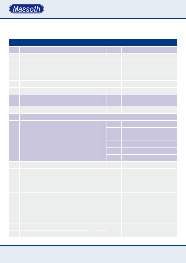
CV - Tabelle (Fahreinstellungen)
Diese Tabelle zeigt die Standardeinstellungen. (S = Standard, A = Analogbetrieb)
Kongurationsvariablen(CV-Tabelle)
CV Beschreibung S A Bereich Bemerkung
1 Lokadresse (standard kurz) 3 1... 127 wenn CV 29, Bit 5 = 0
2 Anfahrspannung (in Fahrstufe 1) 2 1... 255 CV 2 x (1/255 Gleisspannung)
3 Anfahrverzögerung 3 √ 1... 255 CV 3 x 2ms x (1/255 Gleissp.)
4 Bremsverzögerung 3 √ 1... 255 CV 4 x 2ms x (1/255 Gleissp.)
5 Maximale Fahrgeschwindigkeit 255 √ 1... 255 CV 5 x 1/255 Gleisspannung
6 Mittlere Fahrgeschwindigkeit 64 1... 255 CV 6 x 1/255 Gleisspannung
5+6 Registerprogrammiermodus:
Reg 6 = CV ; Reg 5 = Wert
7 Software Versionsnummer --- --- nur lesbar
7 Decoder-Resetfunktion
5 Resetbereiche wählbar.
Wert 55 auch bei Programmiersperre
möglich.
(siehe auch Anhang 10)
8 Herstellerkennung 123 --- nur lesbar
9 Motorfrequenz 0 √ 0... 3 0 = 16 kHz
Funktion der Funktionsausgänge
13
im Analogbetrieb
(An, wenn Funktionswert gesetzt)
15 Programmiersperre 144 0/CV16 Programmierfreigabe
16 Programmiersperre 144 Fixwert LS-Decoder
17 Lange Lokadresse (hohes Byte)
18 Lange Lokadresse (tiefes Byte)
--- --- CV 5 + 6 bleiben erhalten
55 Grundeinstellung
66 Motoreinstellung
77 Licht- & Funktionseinstellung
111 Reset CV 131 – 167
122 Reset CV 171 – 199
133 Reset CV 200 – 212
1 = 2 kHz
2 = 250 Hz
3 = 60 Hz
3 √ 0... 63
128
A3 = 4 Werte der gewünschten
A7 = 64 Funktionen addieren!
A8 = 128
128...
Hohe Lokadresse ist aktiv,
10239
wenn CV 29, Bit5 = 1
38
Page 39
CV - Table (drive settings)
This table shows the standard settings of the S-decoder. (D = Default, A = analog operation)
Tableofcongurationvariables
CV Description D A Range Note:
1 Loco address (Standard short) 3 1... 127 If CV 29 bit 5 = 0
2 Starting voltage 2 1... 255 CV 2 x (1/255 track voltage)
3 Acceleration time 3 √ 1... 255 CV 3 x 2ms x (1/255 track v.)
4 Braking time 3 √ 1... 255 CV 4 x 2ms x (1/255 track v.)
5 Top speed 255 √ 1... 255 CV 5 x (1/255 track voltage)
6 Mid speed 64 1... 255 CV 6 x (1/255 track voltage)
5+6 Programming in register mode:
Reg 6 = CV No. ; Reg 5 = Value
7 Software version --- --- read only
7 Decoder reset functions
5 ranges available.
Value 55 available with programming
lock.
(see also attachment 10)
8 Manufacturer ID 123 --- read only
9 Motor Frequency 0 √ 0... 3 0 = 16 kHz
Function outputs in analog mode
13
(On if value set)
15 Programming lock 144 0/CV16 Programming release
16 Programming lock 144 Fixed value LS-Decoder
17 Long loco address (High Byte)
18 Long loco address (Low Byte)
--- --- CV 5 and CV 6 are not effected
55 basic setting
66 motor setting
77 reset lights and functions
111 reset CV 131 – 167
122 reset CV 171 – 199
133 reset CV 200 – 212
1 = 2 kHz
2 = 250 Hz
3 = 60 Hz
3 √ 0... 63
128
A3 = 4 Add the values to the
A7 = 64 desired functions!
A8 = 128
128...
Only active
10239
if CV 29 bit 5 = 1
39
Page 40

Kongurationsvariablen(CV-Tabelle)
CV Beschreibung S A Bereich Bemerkung
19 Mehrfachtraktionsadresse 0 1... 99
29 NMRA Konguration 4 √ siehe Anhang 1
49 MASSOTH Konguration 0 √ siehe Anhang 2
50 Licht: Dimmwert (PWM) 32 √ 1... 32 32 = volle Gleisspannung
51 Licht vorne Schaltbefehl 128 siehe Anhang 3
52 Licht hinten Schaltbefehl 64 siehe Anhang 3
53 A1 + A2 Dimmwert 32 √ siehe Anhang 4
54 A1 Schaltbefehl 7 siehe Anhang 3
55 A1 Sonderfunktion 0 √ siehe Anhang 5
56 A2 Schaltbefehl 2 siehe Anhang 3
57 A2 Sonderfunktion 0 √ siehe Anhang 5 + 5a
58 Pausenzeit bei Halt mit Richtungsw. 0 √ 0... 255 0,5 Sek pro Wert
59 Rangiergang Schaltbefehl 8 0... 16 0 = deaktiviert
60 Lastregelung max. Nachregelung 2 √ 1... 255 großer Wert = starke Regelung
61 Lastregelung Nachregelverzögerung 60 √ 1... 255 großer Wert = langsame Reg.
62 Lastregelung Nachregelbegrenzung 255 √ 1... 255 1 = schnelle Begrenzung
Verzögerungszeiten aus- und einschal-
64
ten (Schaltbefehlszuordnung )
67
frei programmierbare Fahrkurve
mit 28 Werten
94
Programmieradresse POM
107
(hohes Byte)
Programmieradresse POM
108
(tiefes Byte)
112 A3 + A4 Dimmwert 32 √ siehe Anhang 4
113 A3 Schaltbefehl 3 0... 16 siehe Anhang 3
16 0... 16
39
255
254 = langsame Begrenzung
255 = keine Begrenzung
0 = keine Tastenzuordnung
1..16 = Funktionstaste
1... 255 siehe Anhang 9-
Standard Adresse 10239
40
Page 41

Tableofcongurationvariables
CV Description D A Range Note:
19 Multiple Unit Address 0 1... 99
29 Conguration Table NMRA 4 √ see attachment 1
49 Conguration Table MASSOTH 0 √ see attachment 2
50 Light: Dimming Value (PWM) 32 √ 1... 32 32 = full track voltage
51 Front Light: Command Allocation 128 see attachment 3
52 Rear Light: Command Allocation 64 see attachment 3
53 S1 + S2 Dimming Value 32 √ see attachment 4
54 S1: Command Allocation 7 see attachment 3
55 S1: Special Function 0 √ see attachment 5
56 S2: Command Allocation 2 see attachment 3
57 S2: Special Function 0 √ see attachment 5 + 5a
58 Pause Time for Stop with Reversing 0 √ 0... 255 0,5 sec per value
59 Switching Speed Command Allocation 8 0... 16 0 = deactivated
60 PI-Load Contr. Max. Readjustm. Fact. 2 √ 1... 255 large value = strong readjustm.
61 PI-Load Contr. Readjustm. Retardation 60 √ 1... 255 large value = slow readjustm.
62 PI-Load Contr. Readjustment Strength 255 √ 1... 255 1 = fast limitation
PI-Load control On/Off: Command
64
allocation
67
Freely programmable speed curve in
28 steps
94
Programming address POM
107
(High Byte)
Programming address POM
108
(Low Byte)
112 A3 + A4 Dimming Value 32 √ see attachment 4
113 A3 Command allocation 3 0... 16 see attachment 3
16 √ 0... 16
39
255
254 = slow limitation
255 = no limitation
0 = Off
1..16 = function key
1... 255 see attachment 11-
Standard address 10239
41
Page 42
Kongurationsvariablen(CV-Tabelle)
CV Beschreibung S A Bereich Bemerkung
114 A3 Sonderfunktion 0 √ siehe Anhang 4 + 5
115 A4 Schaltbefehl 4 siehe Anhang 3
116 A4 Sonderfunktion 0 √ siehe Anhang 5 + 5a
121 A7: Schaltbefehl 13 0 ... 16 0 = Licht
123 A8: Schaltbefehl 14 0 ... 16 0 = Licht
124 A7: Servofunktion 0 siehe Anhang 7
125 A7: Servo: untere Drehbegrenzung 16 5 ... 50 An Servo anpassen
126 A7: Servo: obere Drehbegrenzung 32 5 ... 50 An Servo anpassen
127 A7: Servo: Drehgeschwindigkeit 1 1 ... 15 1 = schnell / Einheit = 10 ms
129 Puffernachlaufzeit Digitalbetrieb 0 1... 255 nur bei Pufferbetrieb
130 Puffernachlaufzeit Analogbetrieb 0 √ 1... 255 nur bei Pufferbetrieb
1 ... 16 = Funktionstaste
1 ... 16 = Funktionstaste
CV - Tabelle (Soundeinstellungen)
Kongurationsvariablen(CV-Tabelle)
CV Beschreibung S Bereich Bemerkung
131 Zusatzsound 1: Schaltbefehl * 0...16
132 Zusatzsound 2: Schaltbefehl * 0...16
133 Zusatzsound 3: Schaltbefehl * 0...16
134 Zusatzsound 4: Schaltbefehl * 0...16
135 Zusatzsound 5: Schaltbefehl * 0...16
136 Zusatzsound 6: Schaltbefehl * 0...16
137 Zusatzsound 7: Schaltbefehl * 0...16
138 Zusatzsound 8: Schaltbefehl * 0...16
139 Zusatzsound 9: Schaltbefehl * 0...16
140 Zusatzsound 10: Schaltbefehl * 0...16
141 Zusatzsound 11: Schaltbefehl * 0...16
142 Zusatzsound 12: Schaltbefehl * 0...16
0 = deaktiviert
keine Funktionstaste ist zugeordnet
(Sound kann nicht über die Funktionstaste ausgelöst werden)
1 ... 16 = Zuordnung einer Funktionstaste (Sound wird mit entsprechender Funktionstaste ausgelöst)
Hinweis: Es wird jeweils der erste
Sound der zugeordneten Funktionstaste ausgelöst. Es ist nur eine
Einfachbelegung der Funktionstaste möglich.
42
Page 43
Tableofcongurationvariables
CV Description D A Range Note:
114 A3 Special function 0 √ see attachment 4 + 5
115 A4 Command allocation
116 A4 Special function
121 A7 Switching function 13 0 ... 16 0 = Light
123 A8 Switching function 14 0 ... 16 0 = Light
124 A7 Servo conguration 0 see attachment 7
125 A7 Servo, lower end position 16 5... 50 depending on servo
126 A7 Servo, upper end position 32 5... 50 depending on servo
127 A7 Servo, time base 1 1... 15 1 = fast / 1 unit = 10 ms
129 Buffer runtime digital operation 0 1... 255 buffer operation only
130 Buffer runtime analog operation 0 √ 1... 255 buffer operation only
1 ... 16 = Function key
1 ... 16 = Function key
CV - table (Sound settings)
Tableofcongurationvariables
CV Description A Range Note
131 Add. sound 1 : Switching command * 0...16
132 Add. sound 2 : Switching command * 0...16
133 Add. sound 3 : Switching command * 0...16
134 Add. sound 4 : Switching command * 0...16
135 Add. sound 5 : Switching command * 0...16
136 Add. sound 6 : Switching command * 0...16
137 Add. sound 7 : Switching command * 0...16
138 Add. sound 8 : Switching command * 0...16
139 Add. sound 9 : Switching command * 0...16
140 Add. sound 10 : Switching command * 0...16
141 Add. sound 11 : Switching command * 0...16
142 Add. sound 12 : Switching command * 0...16
0=deactivated:
sound can not be triggered by
F-key
1…16 = F-key assignment:
sound will be triggered by the respective
F-key
Note: Only one sound may be
programmed to an F-key. In case
multiple sounds are assigned to
one F-key only the rst sound
programmed will be triggered.
43
Page 44

Kongurationsvariablen(CV-Tabelle)
CV Beschreibung S Bereich Bemerkung
147 Sound An/Aus: Schaltbefehl 6 0...16
Ab-/Aufrüsten
148
Zylindernebengeräusch bei Dampoks
149 Massoth Soundkonguration 2 0...255 siehe Anhang 7
150 Anfahrsperre während des Aufrüstens 0 0... 3 0=Aus, 1=Dig., 2=An., 3=Dig.+An.
151 Zusatzsound 1: Loopanzahl * 0...16
152 Zusatzsound 2: Loopanzahl * 0...16
153 Zusatzsound 3: Loopanzahl * 0...16
154 Zusatzsound 4: Loopanzahl * 0...16
155 Zusatzsound 5: Loopanzahl * 0...16
156 Zusatzsound 6: Loopanzahl * 0...16
157 Zusatzsound 7: Loopanzahl * 0...16
158 Zusatzsound 8: Loopanzahl * 0...16
159 Zusatzsound 9: Loopanzahl * 0...16
160 Zusatzsound 10: Loopanzahl * 0...16
161 Zusatzsound 11: Loopanzahl * 0...16
162 Zusatzsound 12: Loopanzahl * 0...16
167 Soundtyp-Steuerregister * --- nur lesbar
168 Freigabeschwelle Bremse 64 0...255
169 Auslöseschwelle Bremse 30 0...255
Funktionstaste für Zahnraddampok oder
170
Zweikraftlok (ab V2.5)
171 1. Standgeräusch: Soundzuordnung * 0...12
172 2. Standgeräusch: Soundzuordnung * 0...12
173 3. Standgeräusch: Soundzuordnung * 0...12
174 4. Standgeräusch: Soundzuordnung * 0...12
5 0...16
0 0...16
0 = keine Soundwiederholung
(Der Sound wird mit jeder Auslösung 1 x abgespielt und endet
automatisch.)
1 ... 15 = Anzahl Wiederholungen
(Zum Beispiel die Anzahl der
Glockenschläge oder die zeitliche
Länge einer Pfeife)
16 = Dauersound (Der Sound
wird mit der Funktionstaste
gestartet und solange wiederholt,
bis die Funktionstaste wieder
ausgeschaltet wird)
0 ... 16 = Funktionstaste für
Zahnstangengeräusch oder
Umschaltung E-Lok/Diesellok
0 = kein Sound als Standge-
räusch / 1...12 = Zuordnung der
Zusatzsounds (Die gewählten
Zusatzsounds werden im Stand in
der Reihenfolge 1-4 abgespielt)
44
Page 45

Tableofcongurationvariables
CV Description A Range Note
147 Amplier (Sound) Off/On : Switch. com. 6 0...16
Loco start up/shut down, resp. cylinder
148
sound (Steam engine)
149 Conguration register Massoth-sound 2 0...255 see attachment 7
150 Starting Inhibit between startingphase 0 0... 3 0=off, 1=dig., 2=an., 3=dig.+an.
151 Add. sound 1 : Number of loops * 0...16
152 Add. sound 2 : Number of loops * 0...16
153 Add. sound 3 : Number of loops * 0...16
154 Add. sound 4 : Number of loops * 0...16
155 Add. sound 5 : Number of loops * 0...16
156 Add. sound 6 : Number of loops * 0...16
157 Add. sound 7 : Number of loops * 0...16
158 Add. sound 8 : Number of loops * 0...16
159 Add. sound 9 : Number of loops * 0...16
160 Add. sound 10 : Number of loops * 0...16
161 Add. sound 11 : Number of loops * 0...16
162 Add. sound 12 : Number of loops * 0...16
167 Control register: Type of sound * --- read only
168 Release threshold: Brake 64 0...255
169 Trigger threshold: Brake 30 0...255
Function key for steam rack rail loco and
170
dual power locos (since V2.5)
171 1. Standing noise : Sound assignment * 0...12
172 2. Standing noise : Sound assignment * 0...12
173 3. Standing noise : Sound assignment * 0...12
174 4. Standing noise : Sound assignment * 0...12
5 0...16
0 0...16
0= no sound repetition:
The sound will be triggered only
once
1…15: number of repetitions:
e.g. the number of bell rings or
the blow of a whistle
16: sound steady on:
The sound is started with a F-key
and repeated until the F-function
is switched off
0 ... 16 = F-key for rack rail sound
or switch-over Electric/Diesel
locomotive
0= no standing noise
1…12= assignment of additional
sounds
the sounds selected are played in
the order 1-4 while the loco holds
45
Page 46

Kongurationsvariablen(CV-Tabelle)
CV Beschreibung S Bereich Bemerkung
175 1. Standgeräusch: Loopanzahl * 0...15
176 2. Standgeräusch: Loopanzahl * 0...15
177 3. Standgeräusch: Loopanzahl * 0...15
178 4. Standgeräusch: Loopanzahl * 0...15
179 Zeitwert Zufallsgenerator 3 1...3 1 = häug / 3 = selten Auslesen
180 1. Zufallssound: Soundzuordnung * 0...12 0 = kein Zufallsgeräusch
181 2. Zufallssound: Soundzuordnung * 0...12
182 3. Zufallssound: Soundzuordnung * 0...12
183 4. Zufallssound: Soundzuordnung * 0...12
184 1. Zufallssound: Loopanzahl * 0...15 0 = keine Soundwiederholung
185 2. Zufallssound: Loopanzahl * 0...15
186 3. Zufallssound: Loopanzahl * 0...15
187 4. Zufallssound: Loopanzahl * 0...15
188 Anfahrsignal vorwärts: Soundzuordnung * 0...12
189 Anfahrsignal rückwärts: Soundzuordnung * 0...12
190 (Reed) Kontakt 1: Soundzuordnung * 0...12
191 (Reed) Kontakt 2: Soundzuordnung * 0...12
192 Bremsvorgang: Soundzuordnung * 0...12
193 Startschwelle Sound Analogbetrieb * 0...255
194 Startschwelle Sound Digitalbetrieb * 0...255
195 Taktgeber Steuerregister 0 0...4
196 Dampfstoßdauer 28 0...32 0...32 = Länge des Dampfstoßes
198 Dampfstoßabstand (Radumdrehung) 1 0...16
200 Gesamtlautstärke 32
0 = keine Soundwiederholung
Der Sound wird 1x abgespielt.
1 ... 15 = Anzahl der Wiederholungen z.B. Anzahl Luftpumpenschläge
1...12 = Zuordnung der Zusatzsounds (gewählte Sounds werden
in zufälliger Reihenf. abgespielt)
Der Sound wird 1x abgespielt
1...15 = Anzahl Wiederholungen
z.B. Anzahl Luftpumpenschläge
0 = kein Sound zugeordnet
1...12 = Zuordnung der Zusatz-
sounds (Der gewählte Zusatzsound wird im entsprechenden
Betriebszustand der Lok abgespielt)
Anpassung der Fahrgeräusche im
Anfahrmoment an die Drehzahl
0 = kein externer Taktgeber
1...4 = Anzahl der Magnetpole für
je einen Dampfstoß
0...16 = Multiplikator der Dampfstoßlänge mit Faktor 3
1...63
1 = leise, 63 = laut
(255)
255 = externes Poti
46
Page 47

Tableofcongurationvariables
CV Description A Range Note
175 1. Standing noise : Number of loops * 0...15
176 2. Standing noise : Number of loops * 0...15
177 3. Standing noise : Number of loops * 0...15
178 4. Standing noise : Number of loops * 0...15
179 Time value of random generator 3 1...3 1=frequent / 3=infreq. triggering
180 1. Random sound: Sound allocation * 0...12 0= no random sound
181 2. Random sound: Sound allocation * 0...12
182 3. Random sound: Sound allocation * 0...12
183 4. Random sound: Sound allocation * 0...12
184 1. Random sound: Number of loops * 0...15 0= no sound repetition: the sound
185 2. Random sound: Number of loops * 0...15
186 3. Random sound: Number of loops * 0...15
187 4. Random sound: Number of loops * 0...15
188 moving forward signal sound allocation * 0...12 0= no sound allocated
189 moving backwards signal sound alloc. * 0...12
190 (Reed) contact 1: Sound allocation * 0...12
191 (Reed) contact 2: Sound allocation * 0...12
192 Brake application: Sound allocation * 0...12
193 Trigger threshold sound output analog * 0...255
194 Trigger threshold sound output digital * 0...255
195 Pulse generator control register 0 0...4
196 Duration of a steam chuff 28 0...32 0…32= duration of a steam chuff
198 Spacing between steam chuff 1 0...16
200 Total volume level 32
0= no sound repetition:
the sound will be triggered only
once / 1…15: number of repetitions: e.g. the number of air pump
sounds
1…12= assignment of additional
sounds: the sounds selected are
triggered randomly
will be triggered only once
1…15= number of repetitions:
e.g. number of air pump sounds
1…12= allocation of additional
sounds (The sound selected will
be presented depending on the
operational status of the locomotive)
alignment of the sound to the motor RPM when starting to move
0= no external pulse generator
1…4= number of magnet poles
per each steam chuff
0…16 pause time between chuffs
(only active if CV195 is set to „0“)
1...63
1= low, 63= loud,
or 255
255= ext. potentiometer
47
Page 48
Kongurationsvariablen(CV-Tabelle)
CV Beschreibung S Bereich Bemerkung
201 Individuelle Lautstärke: Zusatzsound 1 * 0...3 0 = Reduzierung auf 25%
202 Individuelle Lautstärke: Zusatzsound 2 * 0...3
203 Individuelle Lautstärke: Zusatzsound 3 * 0...3
204 Individuelle Lautstärke: Zusatzsound 4 * 0...3
205 Individuelle Lautstärke: Zusatzsound 5 * 0...3
206 Individuelle Lautstärke: Zusatzsound 6 * 0...3
207 Individuelle Lautstärke: Zusatzsound 7 * 0...3
208 Individuelle Lautstärke: Zusatzsound 8 * 0...3
209 Individuelle Lautstärke: Zusatzsound 9 * 0...3
210 Individuelle Lautstärke: Zusatzsound 10 * 0...3
211 Individuelle Lautstärke: Zusatzsound 11 * 0...3
212 Individuelle Lautstärke: Zusatzsound 12 * 0...3
217 Lautstärke Einschaltphase * 0...3
218 Lautstärke Standgeräusch * 0...3
219 Lautstärke Ausschaltphase * 0...3
220 Lautstärke Fahrgeräusch * 0...3
221 Lautstärke Einschaltphase * 0...3 Nur für Zweikraftloks
222 Lautstärke Standgeräusch * 0...3
223 Lautstärke Ausschaltphase * 0...3
224 Lautstärke Fahrgeräusch * 0...3
229 Auslöseschwelle 1 Stufensch. Digital 16 0...255
230 Auslöseschwelle 2 Stufensch. Digital 32 0...255
231 Auslöseschwelle 3 Stufensch. Digital 48 0...255
232 Auslöseschwelle 4 Stufensch. Digital 112 0...255
233 Auslöseschwelle 5 Stufensch. Digital 160 0 ... 255
234 Geräusch b. Beschleunigen, Stufensch. 11 0 ... 255
235 Zeit bis Schaltvorgang 4 0 ... 16 (0,15 sec/Wert) 0 = deaktiviert
236 Standzeit für Spannungspuffer -> 0 ... 255 Diesel= 55, Dampf = 250
255 Decodertyp-Kennung nur lesen
1 = Reduzierung auf 50%
2 = Reduzierung auf 75%
3 = Volle Lautstärke 100%
48
Page 49
Tableofcongurationvariables
CV Description A Range Note
201 Add. sound 1: Individual volume level * 0...3 0= 25% volume level
202 Add. sound 2: Individual volume level * 0...3
203 Add. sound 3: Individual volume level * 0...3
204 Add. sound 4: Individual volume level * 0...3
205 Add. sound 5: Individual volume level * 0...3
206 Add. sound 6: Individual volume level * 0...3
207 Add. sound 7: Individual volume level * 0...3
208 Add. sound 8: Individual volume level * 0...3
209 Add. sound 9: Individual volume level * 0...3
210 Add. sound 10: Individual volume level * 0...3
211 Add. sound 11: Individual volume level * 0...3
212 Add. sound 12: Individual volume level * 0...3
217 Volume turn-on phase * 0...3
218 Volume standing phase * 0...3
219 Volume turn-off phase * 0...3
220 Volume driving phase * 0...3
221 Volume turn-on phase * 0...3 two force locomotives only
222 Volume standing phase * 0...3
223 Volume turn-off phase * 0...3
224 Volume driving phase * 0...3
229 Trigger threshold 1 contact switch dig. 16 0...255
230 Trigger threshold 2 contact switch dig. 32 0...255
231 Trigger threshold 3 contact switch dig. 48 0...255
232 Trigger threshold 4 contact switch dig. 112 0...255
233 Trigger threshold 5 contact switch dig. 160 0 ... 255
234 Sound on accelerate, contact switch 11 0 ... 255
235 Switching timer 4 0...16 (0,15 sec/value) 0 = deactivated
236 Power Buffer timer -> 0 ... 255 Diesel = 55 / Steam = 250
255 Decoder type read only
1= 50% volume level
2= 75% volume level
3= 100% maximum volume
49
Page 50
Anhang1:CV29-NMRAKongurationsregister
Bit Wert AUS (Wert=0) AN Bemerkung
0 1 normale Fahrtrichtung inverse Fahrtrichtung
1 2 14 Fahrstufen 28 Fahrstufen
2 4 nur Digitalbetrieb Digital + Analogbetrieb
3 - - -
4 16 interne Fahrkurve programmierbare Fahrkurve CV 67 - 94
5 32 kurze Lokadresse (CV 1) lange Lokadr. (CV 17+18)
Anhang 1a : Grundlegende Werte für CV 29
Wert Funktion
0 14 Fahrstufen + Analog gesperrt
2 28 Fahrstufen + Analog gesperrt
4 14 Fahrstufen
6 28 Fahrstufen
34 Lange Lokadresse + 28 Fahrstufen + Analog gesperrt
38 Lange Lokadresse + 28 Fahrstufen
Anhang2:CV49-MASSOTHKongurationsregister
Bit Wert AUS (Wert 0) AN Bemerkung
0 1
1 2 digitale Lastregelung AUS digitale Lastregelung AN
2 4 analoge Lastregelung AUS analoge Lastregelung AN
3 8 --- ---
4 16 Massoth Bus SUSI Bus
5 32 Feststellbremse AUS Feststellbremse AN
nur parallele
Funktionsdatenverarbeitung
parallele + serielle
Funktionsdatenverarbeitung
128 Fahrstufen werden
automatisch erkannt
Seriell/Parallel wird bei
„An“ automatisch erkannt
50
Page 51
Attachment2:CV49-MASSOTHcongurationtable
Bit Value OFF (Value=0) ON Note
0 1 Standard Driving Direction Reverse Driving Direction
1 2 14 Speed Steps 28 Speed Steps
2 4 Digital Operation Only Digital + Analog Operation
3 - - -
4 8 Internal Driving Curve Programmable Driving Curve
5 16 Short Address (CV1) Long Address (CV 17+18)
Attachment 1a : Basic values of CV29
Value Function
0 14 speed steps + analog operation blocked
2 28 speed steps + analog operation blocked
4 14 speed steps
6 28 speed steps
34 long address + 28 speed steps + analog operation blocked
38 long address + 28 speed steps
Attachment2:CV49-MASSOTHcongurationtable
Bit Value OFF (Value=0) ON Note
0 1 Parallel data transfer only Serial + parallel data transfer
1 2 Digital load control = OFF Digital load control = ON
2 4 Analog load control = OFF Analog load control = ON
3 8 --- ---
4 16 Massoth bus SUSI bus
5 32 electronic parking brake OFF electronic parking brake ON
automatic recognition
of 128 speed steps
automatic detection
of serial/parallel
51
Page 52
Anhang 3: CV 51, 52, 54, 56, 113, 115
Schaltbefehlszuordung Licht vorn / hinten, A1, A2, A3, A4
Wert Verwendung Bemerkung
0 = Schalten mit der Lichttaste
0... 16
1 ... 16 = Schalten mit der Funktionstaste
31 Schaltausgang immer an nur A2, A4
(0... 16)
Schaltausgang nur bei Rückwärtsfahrt an Zusatzwert aufaddieren
+ 64
(0... 16)
Schaltausgang nur bei Vorwärtsfahrt an Zusatzwert aufaddieren
+ 128
Anhang 4: CV 53, 112 - Dimmfunktion A1, A2, A3, A4
Wert Verwendung Bemerkung
Prozentuale Spannung am Ausgang
1... 32
(beide Ausgänge gedimmt)
(1... 32)
Nur A1 bzw. A3 wird gedimmt
+ 64
(1... 32)
Nur A2 bzw. A4 wird gedimmt
+ 128
Anhang 5: CV 55, 57, 114, 116 - Sonderfunktion A1, A2, A3, A4
Wert Verwendung Bemerkung
0 = Dauerbetrieb des Ausgangs
0
(Normale Schaltfunktion)
Dauerhaftes symmetrisches Blinken
1... 15
(Zeitbasis 0,25 sec pro Wert)
(1... 15)
Kurzzeitfunktion, Monoop
+ 64
(Zeitbasis 0,25 sec pro Wert)
(1... 15)
Asymmetrisches Blinken 1/3 an - 2/3 aus
+ 128
1 Einheit = ~3% der Gleisspannung
1 = 3% der Gleisspannung (0,75V)
32 = 100% der Gleisspannung (24V)
A1 = Wert in CV53
A3 = Wert in CV112
A2 = Wert in CV53
A4 = Wert in CV112
Ausgang blinkt symmetrisch
Ausgang schaltet sich nach der
abgelaufenen Zeit automatisch aus.
Zusatzwert Bitte aufaddieren.
kurz an / lang aus
Zusatzwert Bitte aufaddieren.
52
Page 53
Attachment 3: CV 51, 52, 54, 56, 113, 115
Switch output commands Light front / rear, A1, A2, A3, A4
Value Application Note
0 = Switch function with light key,
0... 16
1 ... 16 = Switch function with F-key No. 1-16
31 Switching output always on only A2, A4
(0... 16)
Switching output "on" in reverse Only additional value must be added
+ 64
(0... 16) +
Anhang 4: CV 53, 112 - Dimmfunktion A1, A2, A3, A4
Attachment 5: CV 55, 57, 114, 116 - Special functions A1, A2, A3, A4
Switching output „on“ in forward Only additional value must be added
128
Value Application Note
Voltage in Percent of Track Voltage on Output
1... 32
(Both outputs dimmed)
(1... 32)
A1 resp. A3 is dimmed only
+ 64
(1... 32)
A2 resp. A4 is dimmed only
+ 128
Value Application Note
0 = Steady „on“
0
(Standard operation)
Flashing symmetrical
1 - 15
(Time base 0,25 sec/value)
Short term function (Monoop)
+ 64
(Time base 0,25 sec/value)
+ 128 Asymmetric ashing (1/3 on, 2/3 off)
1 Unit = approx. 3% of track voltage
1 = 3% of track voltage (0.75V)
32 = 100% track voltage (24V)
S1 = value in CV53
S3 = value in CV112*
S2 = value in CV53
S4 = value in CV112*
symmetric ashing
output switches off after time
out
additional value must be added
short „on“, long „off“
additional value must be added
53
Page 54
Anhang 5: CV 55, 57, 114, 116 - Sonderfunktion A1, A2, A3, A4
Wert Verwendung Bemerkung
(1... 15)
Asymmetrisches Blinken 2/3 an - 1/3 aus
+ 192
Anhang 5a: CV 57, 114, 116 - Sonderfunktion A2, A3, A4
Wert Verwendung Bemerkung
16 Inverse Kopplung zu A1, A3 oder A5 (Wechselblinken)
30 Taktsimulation für gepulsten Verdampfer (nur A3) CV 114
Anhang 6: CV 124 - Servofunktion A7
Wert Verwendung Bemerkung
0 0 = Servo deaktiviert Normaler Schaltausgang
1 1 = Servo aktiv
+ 4 Pegel invertiert
+ 8 Abschaltung nach Bewegung
Anhang7:CV149-MASSOTHSoundkonguration
Bit Wert AUS (Wert 0) AN Bemerkung
0 1 Zufallsgenerator AUS Zufallsgenerator AN
1 2 Standgeräusch AUS Standgeräusch AN
2 4 Normales Fahrgeräusch Lastabhäng. Fahrgeräusch
3 8 Zylinderhähne zu Zylinderhähne offen
4 16
5 32
6 64 Anfahrsignal Sperrzeit aus Anfahrsignal Sperrzeit ein erst ab V1.2 (steht in CV 7)
Reedkontakteingänge
normal
autom. Nebengeräusche
AUS
Reedkontakteingänge
richtungsabhängig
autom. Nebengeräusche
lang an / kurz aus
Zusatzwert Bitte aufaddieren.
CV 57 (A2 an A1)
CV 116 (A4 an A3)
Nur beim Anfahren einer
Dampok
AKTIV
54
Page 55
Attachment 5: CV 55, 57, 114, 116 - Special functions A1, A2, A3, A4
Value Application Note
+ 192 Asymmetric ashing (2/3 on, 1/3 off)
Attachment 5a: CV 57, 114, 116 - Special functions A2, A3, A4
Value Application Note
16 Inverse Coupling with A1, A3 or A5 (Alternating Flashing)
30 Pulse simulation for pulsed smoke generator (A3 only) CV 114
Attachment 6: CV 124 - Servo function A7
Value Application Note
0 0 = Servo deactivated regular switching output
1 1 = Servo activated
+ 4 Control level inverted
+ 8 Switch-off after movement
Attachment7:CV149-MASSOTHSoundConguration
Bit Value OFF (Value 0) ON Note
0 1 Random generator OFF Random generator ACTIVE
1 2 Standing phase noise OFF Standing phase noise ACTIVE
2 4 Standard driving Sound Load-dependent sound
3 8 Cylinder valves closed Cylinder valves open
4 16 Contacts standard
5 32
6 64 Start signal delay OFF Start signal delay ON
Automatic side noises
OFF
Reed contact inputs
direction sensitive
Automatic side noises
ACTIVE
short „off“, long „on“
additional value must be added
CV57 (A2 with A1)
CV116 (A4 with A3)
only steam locos during
start of movement
since V1.2 (written in
CV 7)
55
Page 56
Anhang 8: CV-Werte bei Decoder-Resetfunktion
Resetwert
55 1 17 18 29 49 58 59
66 2 3 4 5 6 9 60 61 62 63 64
77 13 112 113 114 121 123 124 125 126 127 129 130
111 CV 131 – CV 167 Reset Soundfunktionen
122 CV 171 – CV 199 Reset Standphase
133 CV 200 – CV 220 Reset Lautstärkeeinstellungen
(+ CV221 - CV 224 bei Zweikraftlok)
Anhang 9: Grundwerte der frei programmierbaren Fahrkurve (CV 67 - 94)
CV 67 68 69 70 71 72 73 74 75 76 77 78 79 80 81
Wert 6 8 10 13 16 19 22 26 31 36 42 48 54 60 68
CV 82 83 84 85 86 87 88 89 90 91 92 93 94
Wert 76 84 92 102 112 124 136 152 168 188 208 228 232
56
Page 57
Attachment 8: Default settings at resets
Reset value
55 1 17 18 29 49 58 59
66 2 3 4 5 6 9 60 61 62 63 64
77 13 112 113 114 121 123 124 125 126 127 129 130
111 CV 131 - CV 167 Reset soundfunctions (Values depends on type of sound)
122 CV 171 - CV 199 Reset standing phase (Values depends on type of sound)
133 CV 200 - CV 220 Reset sound volume settings
(+ CV 221 - CV 224 two force locomotives)
Attachment 9: Basic values of freely programmable driving curve (CV 67 - 94)
CV 67 68 69 70 71 72 73 74 75 76 77 78 79 80 81
Value 6 8 10 13 16 19 22 26 31 36 42 48 54 60 68
CV 82 83 84 85 86 87 88 89 90 91 92 93 94
Value 76 84 92 102 112 124 136 152 168 188 208 228 232
57
Page 58

13. Technische Daten
Spannung
0-24 V DC/DCC (kurzzeitig max. 27V)
Stromaufnahme
30-500 mA (ohne Motor + Funkt.)
Maximaler Motorstrom 1,5A
Maximaler Funktionsstrom 1,2A
A1-A4 je 0,3A (max 22V)
A7-A8 je 10mA (max 5V)
Lautsprecher
8 Ohm (mind. 1,5W)
Temperaturbereich
-20 ... +45°C
Abmessungen
53,5 x 25 x 15 mm (L x B x H)
13. Technical Data
Power supply
0-24 Volts DC/DCC (max. peak 27V)
Current
30-500 mA (w/o motor + functions)
Maximum Motor current 1,5A
Maximum function current 1,2A
A1-A4 each 0,3A (max. 22V)
A7-A8 each 10mA (max. 5V)
Loudspeaker
8 Ohm (at least 1,5W)
Temperature range:
-20°C ... +45°C / -4°F to 113°F
Measurements
53,5 x 25 x 15 mm (L x W x H)
Hinweis zur Temperatur: Um
Kondenswasserbildung zu vermeiden benutzen Sie die Elektronik bei
Temperaturen unter 0°C nur, wenn
diese vorher aus einem beheizten
Raum kommt. Die Eigenwärme des
Fahrbetriebs reicht aus um Kondenswasserbildung zu verhindern.
14. Garantie, Reparatur, Kundendienst
MASSOTH gewährt die Fehlerfreiheit
dieses Produkts für ein Jahr. Die
gesetzlichen Regelungen können
in einzelnen Ländern abweichen.
Verschleißteile sind von der Garantieleistung ausgeschlossen. Berechtigte
Beanstandungen werden kostenlos
behoben. Für Reparatur- oder
58
Note: In case you intend to utilize this
decoder below freezing temperatures,
make sure it was stored in a heated
environment before operation to
prevent the generation of condensed
water. The heat generated during
operation is sufcient to prevent
condensed water.
14. Warranty, Service, Support
MASSOTH warrants this product
against defects in materials and
workmanship for one year from
the original date of purchase. Other
countries might have different legal
warranty situations. Normal wear and
tear, consumer modications as well
as improper use or installation are
Page 59

Serviceleistungen übergeben Sie das
Produkt bitte Ihrem Fachhändler oder
senden es direkt an den Hersteller.
Unfrei zurückgesendete Sendungen
werden nicht angenommen. Eine
Kopie des Kaufbelegs wird vorausgesetzt. Für Schäden durch unsachgemäße Behandlung oder Fremdeingriff
oder Veränderung des Produkts
besteht kein Garantieanspruch. Der
Anspruch auf Serviceleistungen
erlischt unwiderruich.
Irrtümer und Änderungen vorbehal-
ten. Auf unserer Internetseite nden
Sie die jeweils aktuellen Broschüren,
Produktinformationen, Dokumentation und Softwareprodukte rund um
MASSOTH-Produkte.
15. Hotline
Serviceanfragen richten Sie bitte an:
Massoth Elektronik GmbH
Mo 14:00-17:30 sowie
Do 8:00-12:00
FON +49 (0)6151-35077-38
FAX +49 (0)6151-35077-44
not covered. Peripheral component
damage is not covered by this
warranty. Valid warranty claims will
be serviced without charge within the
warranty period. For warranty service
please return the product to you
dealer or send it directly to the manufacturer. Return shipping charges
are not covered by MASSOTH. Please
include your proof of purchase with
the returned goods.
Errors and changes excepted. Please
check our web site for up to date
brochures, product information,
documentation and software updates.
15. Hotline
For technical support contact:
Massoth Elektronik GmbH, Germany
Mo 2:00-5:30 p.m.
Thu 8:00-12:00 a.m.
FON +49 (0)6151-35077-38
FAX +49 (0)6151-35077-44
RoHS
COMPLIANT
032377o
59
Page 60

QUALITY
MADE IN
GERMANY
Massoth Elektronik GmbH
Frankensteiner Str. 28 · D-64342 Seeheim · Germany
FON: +49 (0)6151-35077-0 · FAX: +49 (0)6151-35077-44
eMail: [email protected] · www.massoth.de
991031 BDA eMOTION LS 2014.10
 Loading...