

Page 1
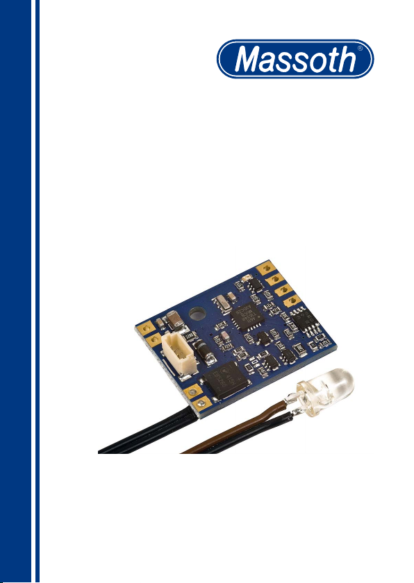
PZB/IR Empfänger
ITC/IR Receiver
8172510
Page 2

Inhaltsverzeichnis
1. Allgemeines
1.1. Warnhinweise
2. Grundsätzliche Informationen zum PZB/IR-System
2.1. Funktionsumfang PZB-Signalempfänger
2.2. Lieferumfang
2.3. Wichtige Grundeinstellungen im Auslieferungszustand
3. Anschluss
3.1. Susi-Bidi-Kabel
3.2. Steuerkontakt
3.3. Funktionsausgang FA1
3.4. Test-LED
3.5. Montage
4. Nutzbare Sendebefehle
4.1. Positionsadresse und Signalzustand
4.2. Automatikfunktionen
4.3. Funktionsauslösung direkt
4.4. Funktionsauslösung indirekt (numerisch)
5. Erweiterte Funktionen
5.1. PZB-Signalhalt aufheben
5.2. PZB-Sonderbefehle
6. Programmierung
6.1. Adressberechnung
6.2. Binäre CVs
6.3. Programmiersperre CV15/16
6.4. Resetfuntion
6.5. Firmware-Update
7. Technische Daten
8. Pege
9. Gewährleistung & Kundendienst
10. Hotline
11. CV-Tabelle
2
Page 3

Table of Contents
1. General Information
1.1. Warning Notes
2. General Information on the ITC/IR System
2.1. Functional Range of the ITC-Sender
2.2. Scope of Supply
2.3. Important basic settings on delivery status
3. Installation
3.1. Susi-Bidi-Cable
3.2. Control Contact
3.3. Function Output FA1
3.4. Test-LED
3.5. Installation
4. Available operation commands
4.1. Position address and signal state
4.2. Automatic functions
4.3. Direct function activation
4.4. Numeric function activation (indirect)
5. Extended features
5.1. ITC-Signalstop deactivation
5.2. ITC Special Features
6. Programming
6.1. Address Calculation
6.2. Binary CVs
6.3. Programming Lock CV15/16
6.4. Reset function
6.5. Firmware Update
7. Technische Specications
8. Maintenance
9. Warranty & Service
10. Hotline
11. CV-Tabelle
3
Page 4

1. Allgemeines:
Sehr geehrte Kundin, sehr geehrter
Kunde! Wir beglückwünschen sie
zu der Entscheidung das speziell
für Gartenbahnen entwickelte Massoth-Infrarot-Steuerungssystem
„Punktförmige Zugbeeinussung“,
kurz PZB/IR-System, zu erwerben
und ihre wertvollen Fahrzeuge
damit auszurüsten. Das PZB/IRSystem orientiert sich vollumfäng-
lich am „großen Vorbild“. Dort
bezeichnet „Punktförmige Zugbe-
einussung (PZB)“ verschiedene
Systeme, die an ausgewählten
Punkten einer Eisenbahnstrecke
eine Überwachung und Beeinussung schienengebundener Fahrzeuge ermöglichen. Überwacht
wird dort beispielsweise bei aktuell
gebräuchlichen Systemen unter
anderem, ob ein „Halt“ zeigendes
Signal nicht überfahren wurde.
Wir empfehlen diese Produktdokumentation und vor allem aber die
Warnhinweise vor der Inbetriebnahme unbedingt gründlich zu
lesen und diese zu beachten. Für
Schäden bei Nichtbeachtung übernimmt Massoth keine Haftung!
Sollten sie zu Technik und Einbau
über diese Anleitung hinausgehende Fragen haben kontaktieren sie bitte unsere Hotline,
1. General Information
Dear Customer,
congratulations on your decision
to purchase Massoth-infraredControlsystem „Intermittent Train
Control“ aka DiMAX-ITC-System
and to equip your valuable trains
with it.
The ITC-System is based on the
original big role model with its
intermittent train controle, which
means, that on different locations
throughout the railroad line different systems supervise and control
rail-bound vehicles. It monitors
for example if a „Stop“ sign is not
run-over.
We advice you to read all instructions and especially Caution
notes prior to operating the ITC
components. Massoth Electronics assumes no liability for any
damages caused by nonobservance. If you have any further
questions concerning technical
specics or installation, please
contact our hotline (see Hotline information under 10).
4
Page 5

Erreichbarkeit siehe Punkt 10.
1.1 Warnhinweise:
Dieses Produkt ist kein Spielzeug.
Verbinden sie den MassothPZB-Signalempfänger mit dem
Gleisstrom und mit der Fahrzeugelektronik sorgfältig nach
dem Anschlussplan (Bild 1). Der
Massoth-PZB-Signalempfänger ist
generell gegen Kurzschlüsse oder
Überlastung gesichert. Werden
jedoch beim Anschließen Kabel
vertauscht oder Kabel verschiedener Funktionen (z.B. Eingänge und
Ausgänge) kurzgeschlossen, kann
diese Sicherung nicht wirken und
die Elektronik wird zerstört.
Das Bauteil darf nur an Modellbahnanlagen mit den dort üblichen
Spannungen und Bus-Daten
angeschlossen werden. Ein Anschluss an andere Geräte kann zur
Zerstörung führen.
1.1 Warning Notes
This product is no toy.
Please connect the Massoth ITCsignalreceiver carefully to the track
current and the vehicle electronic
according to the connecting diagram (see picture 1) .
The Massoth ITC-Signalreceiver
is basically secured against short
circuits or overloads. But if there
are any wires invertet, incorrectly
attached or wires of functions (e.g.
input, output) short-circuited, the
fuse is deactivated and the decoder
will therefore be destroyed.
This device may only be installed
at model train layouts with its
standard voltages and Bus-data.
Any connection to other technical
devices may lead to its destruction.
5
Page 6

2. Grundsätzliche Informationen
zum PZB/IR-System
Das PZB/IR Steuerungssystem
ist eine innovative vom digitalen Gleissignal unabhängige
Übertragung von Daten an frei im
Gleis wählbaren Positionen an ein
darüber fahrendes Fahrzeug. Es
erweitert die allgemeine -meist
digitale- Steuerung von Fahrzeugen um spezielle ortsbezogene
Befehle. Somit ist diese Steuerung
auch für Fahrzeuge mit geeigneter
Elektronik nutzbar, die unabhängig vom Gleissignal, z.B. im
Funkbetrieb, gefahren werden.
Die Daten werden permanent
per Infrarotsignal gesendet.
Ausgesandte Befehle können von
digitalen Kommandos auf dem
Gleis beeinusst werden, um zum
Beispiel eine Signalstellung in
das Fahrzeug zu übertragen und
somit die Lokomotive vor dem
„rot“ zeigenden Signal anzuhalten.
Der Befehl kann aber auch vom
Gleissignal unabhängig sein,
um Funktionen im Fahrzeug zu
schalten (Licht an/aus) oder eine
automatische Funktion (Bahnhofshalt und/oder Pfeifsignal vor
Bahnübergang) auszulösen.
Der große Vorteil des DiMAX-PZB-
2. General Information
on the ITC/IR-System
The Massoth DiMAX ITC-System is
an inovative way to transmit data
to any location on the tracks and
the vehicle driving by it, independent from the digital tracksignals.
It upgrades the general (mostly
digital) controle of vehicles to
special, location-dependent
commands. This means, you can
also use it to operate vehicles
with adequate electronic, which
are independently operated from
the track signal (e.g. via radio
controle).
The Data is permanently transmitted through a infrared signal.
Sent-out orders can be inuenced
by digital commands on the
tracks, for example, in order to
transmit a signal to a vehicle and
therefore stop a train in front of
a redlight.
The command can also be
independent from the track signal,
to operate functions such as light
on/off in a train or initiate an
automatic function (train station
stop or whistle in front of a crossing). The great advantage of the
DiMAX-ITC-System is the simple
installation. In order to initiate
location-dependent functions,
6
Page 7

Systems liegt im sehr einfachem
Anschluss. Um ortsbezogene
Funktionen wie zum Beispiel
einen Signalhalt zu erzeugen sind
keine Trennstellen im Gleis oder
aufwändige Verkabelung nötig.
Gerade im Freilandbetrieb ist dies
eine große Arbeitsersparnis und
macht zudem den dauerhaften
Betrieb deutlich zuverlässiger.
Die PZB-Steuerung ist somit die
optimale Ergänzung zu bereits
eingesetzten Digitalsystemen. Über
zusätzlich integrierbare Rückmeldefunktionen (z.B. Railcom® oder
MfX®) können die Informationen
vom Fahrzeug an die Zentrale
zurück gemeldet werden. Somit
ist es möglich auch PC-gesteuerte
Anlagen mit relativ wenig Verkabelungsaufwand voll zu automatisieren. Der Grundaufbau besteht aus
dem PZB-Signaldecoder, welcher
an der gewünschten Position in
das Gleis gesetzt wird, sowie dem
in der Lokomotive eingebauten
DiMAX-PZB-Empfänger, der mit
der Fahrzeugelektronik (z.B. DCCDecoder) verbunden wird. Der
Fahrzeugdecoder muss für den
Anschluss des PZB-Empfängers
geeignet sein. Entsprechende Hin-
weise zur Kompatibilität nden die
such as Stop-signals, you do not
need any cut-off points on the
tracks or complex wiring.
Especially for the outdoor layouts,
this means a great saving of labor
and also makes the long-lasting
performance more reliable.
The ITC is therefore the ideal
addition to a already implemented
digital controle system. You can
feedback the train information to
the central station via the additionally integrable feedback-function
(e.g. Railcom® or MfX® ). This
means it is possible to also fully
automate PC-controlled layouts
without extensive wiring.
The basic structure consists of
the ITC-signal-decoder, which is
installed at the chosen location on
the tracks, and the DiMAX-ITC-
receiver, which is implemented
to the train and connected to the
vehicle electronic (e.g. DCCdecoder). The decoder must be
adequate for the connection of
the ITC-receiver. Please nd the
necessary indication in the Instruction manual of the ITC-Receiver
and decoder.
7
Page 8

in dieser Anleitung und in der Bedienungsanleitung des Decoders.
2.1 Funktionsumfang PZB-Signalempfänger
• IR-Empfänger zum Anschluss an
Decoder nach SUSI-Bidi-Norm.
• Sehr einfacher Anschluss mit je
zwei Kabeln an Digitalgleis und
Empfänger LED und Steuerausgang über Susi-Bidi Bus oder
Schaltkontakt zum Decoder.
• Empfang einer ortsbezogenen
Positionsadresse vom Gleis
• Auswertung von Signalzuständen
für aktiven Signalhalt
• Erweiterte Zubehörbefehle für
komplexere Signalbilder nutzbar
• Rotsperren-Erkennung für Signaldurchfahrt in Gegenrichtung
• Automatikfunktionen für Bahnhofshalte oder Pendelfunktionen
• Schalten von Sonderfunktionen im
Fahrzeug
• Funktionsausgang für Sonderfunktionen mit Funktionsmapping
• Einfache CV-Programmierung
2.1 Funtional Range of the ITCReceiver
• IR-Receiver for connection with
decoders via SUSI-Bidi-Standard.
• Easy installation with only two
cables each at the digital track
and the receiver LED and Control
output via Susi-Bidi Bus or switchcontact to the decoder.
• Reception of a location-related
position address from the track
• Analysis of signal statuses for an
active Stopsignal
• Extended commands for complex
signals
• Redlight-detection for the signal
crossing in the opposite direction
• automatic functions for the train
station stops or commuting functions
• Controlling special features in the
vehicle
• Function output for special features with function mapping
• Easy CV-Programming
8
Page 9

• Resetfunktion
• Updatemöglichkeit
• Reset-function
• Update option.
2.2 Lieferumfang
• PZB-Empfänger
• PZB-Infrarot-LED mit Kabel
• Susi-Kabel
• Bedienungsanleitung
Je nach Packungsvariante können
mehrere Teile als Set enthalten
sein.
2.3 Wichtige Grundeinstellungen im
Auslieferungszustand
• Lokadresse = 3 (CV1=3)
• Signaladresse (für Grünbefehl)
(CV31+32 = 1998, CV229=128)
• DCC-Konguration = Kurze
Lok_adresse ( CV29 = 0)
• Programmiersperre = offen
( CV15+CV16 = 226 )
• Susi-Bidi-Bus = Modul 1
( CV230 = 1 )
LOKADRESSE
Programmieren Sie den Empfänger auf die gleiche Lokadresse
wie der Lokdecoder auch.
2.2 Scope of supply
• ITC-Receiver
• ITC-infrared LED with cable
• Susi-cable
• Instruction Manual
Depending on the version, there
can be several components
included as a set.
2.3 Important basic setting on delivery status
• Train address = 3 (CV1=3)
• Signal address (for greenlight
order) (CV31+32 = 1998)
• DCC-conguration = short train
address (CV29 =0)
• programming lock = open
(CV15+CV16 =226)
• Susi-Bidi-Bus = module 1
(CV230 = 1)
LOCO ADDRESS
Programm the Reciever
to the same Loco address
as the loco decoder.
9
Page 10
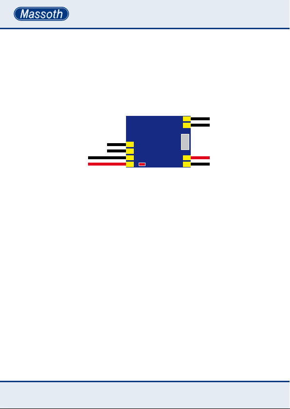
3. Anschluss
Der Signaldecoder wird über die
schwarzen Kabel an den Gleiseingang im Fahrzeug angeschlossen.
Die PZB-Empfänger-LED muss
polungsrichtig gemäß Bild 1
angelötet werden.
FA1(-)
DEC+
GND
Test-LED
Kontakt / Contact(?)
Abbildung 1: Anschlüsse auf dem PZB/IR-Empfänger
Illustration 1: Connections of the ITC/IR Reciever
3. Installation
Using the black cable, the IRsignaldecoder is being connected
to the track input in the vehicle.
The ITC-Receiver-LED has to be
soldered on with the correct polarity direction.
Gleis
Track
SUSI
LED
3.1 Susi-Bidi-Kabel
Sofern die Fahrzeugelektronik
Susi-Bidi unterstützt, sollte die
Verbindung mit dem beiliegenden
Susi-Kabel hergestellt werden. Damit sind alle Funktionen nutzbar.
Am Susi Bus dürfen maximal drei
Susi Module gleichzeitig betrieben
werden. Hierzu muss jedes Modul
eine Adresse (1-3) erhalten.
Die Adresse wird in CV230 programmiert und darf nicht doppelt
vergeben sein.
10
3.1 Susi-Bidi-cable
If the vehicle electronic supports
the Susi-Bidi, the connection
should be installed using the
Susi-cable. This way all features
are available. You can run up to
three Susi-modules on the Susi
Bus. Each module will then need
its own address (1-3).
The address can be programmed
on CV230 and may not be used
twice.
Page 11

3.2 Steuerkontakt
Unterstützt die Fahrzeugelektronik
den Susi-Bidi-Bus nicht, kann
die Steuerung gemäß Bild 2 über
den Kontaktausgang erfolgen.
Der Steuerkontakt kann allerdings
nur für den einfachen Signalhalt
genutzt werden. Automatikbetrieb
oder Schaltfunktionen sind hier
nicht möglich. Folgende Massoth
eMOTION-Decoder ohne SusiBidi-Schnittstelle unterstützen
diese eingeschränkte Funktion:
eMOTION XL, L, XXL
3.2 Control contact
If the vehicle electronic does not
support the Susi-Bidi-Bus, you
can operate as shown in picture 2
through the control contact. You
can only use the control contact
for a simple signal stop. Automatic
operation or switch functions
are not available. The following
Massoth eMOTION-Decoders
without Susi-Bidi-Interface support these limited functions:
eMOTION XL, L, XXL
3.3 Funktionsausgang FA1
Der Funktionsausgang (CV110)
unterstützt die indirekten IRFunktionen 0 (Licht) und 1...28.
3.4 Test-LED
Die Test-LED zeigt den Empfang
von IR-Daten an.
3.5 Montage
Der IR-Signalempfänger kann
mit einer Schraube oder einen
Klebepad an passender Stelle
im Fahrzeug befestigt werden.
Dabei ist darauf zu achten, dass
der Empfänger keine leitende
Verbindung zu anderen Bauteilen
oder Metalloberächen hat. Zur
Montage der IR-LED ist in der
3.3 Function Output FA1
The Function Output FA1
supports the numeric IRFunctions 0 (Light) and 1...28.
3.4 Test-LED
The Test-LED indicates the reception of IR-commands.
3.5 Installation
The IR-Signal-receiver can be attached to the vehicle with a screw
or tape strip. Please ensure that
the receiver does not have any
electrically conducting connection
to another component or metal
surface. To install the IR-LED,
you need to drill a hole into the
drive unit – centric and as close
11
Page 12

Antriebseinheit, möglichst nahe
an einer Achse, mittig ein Loch
(Durchmesser 4,9mm) zu bohren.
Die von oben eingesteckte IR-LED
sollte von hinten mit einem Tropfen Kleber xiert werden. Das Kabel ist polungsrichtig gemäß Bild
1 am PZB-Empfänger anzulöten.
Der Abstand der Empfänger-LED
zur Schienenoberkante darf 5 bis
20 mm (optimal 10mm) betragen.
as possible to the axle (4,9mm
diameter). The IR-LED which is
inserted from above, should be
xated from the back with some
glue. The cable needs soldered to
the ITC-receiver with correct polarity (see picture 1). The maximum
distance of the receiver-LED and
the rail level may vary between 5
and 20 mm (best is 10mm).
4. Nutzbare Sendebefehle
Der PZB-Empfänger kann gleichzeitig bis zu vier unterschiedliche
Informationen nach „MassothPZB-Norm“ empfangen und verarbeiten. Nur über den Susi-Bidi-Bus
sind alle nachfolgend unter Ziffer
4.1 – 4.4 aufgeführten Befehle
nutzbar. Eine Erweiterung ist
mittels Update ist in Planung.
4.1 Positionsadresse und
Signalzustand
Der Empfänger erkennt automatisch ob es sich um eine Standard-
signal oder ein mehrbegrifges
Signal handelt. Er wertet den zugehörigen Signalzustand vollautomatisch aus und leitet die empfangen
Befehle für Fahrt, Langsamfahrt
oder Halt an den Fahrzeugdecoder
weiter. Da der letzte Signalzustand
12
4. Available operation commands
The ITC-Receiver can simoultaneously receive and process up to
four different Massoth-ITC-Standard informations. The following
list of commands (see 4.1-4.4) is
only available with the Susi-BidiBus. More functions are projected.
4.1 Position address and
signal state
The receiver automatically identi-
es a simple or complex signal. It
analyses the according signal state
automatically and transfers commands such as drive, slow drive or
stop to the vehicle decoder. Since
the latest signal state is being
saved internally, the data is still
available after a voltage interrup-
Page 13

intern gespeichert wird sind nach
einer Spannungsunterbrechung (z.
B. Nothalt) alle Daten vorhanden.
tion (e.g. emergency stop).
4.2 Automatikfunktionen
Der PZB-Empfänger kann
folgende Funktionen der PZBSender auswerten und an die
Fahrzeugelektronik weiterleiten:
1. Langsamfahrt (auch in
Kombination mit den folgenden
Funktionen)
2. Weiterfahrt in gleicher Richtung
nach Zeitablauf (einfacher Bahnhofshalt)
3. Vorwärtsfahrt nach Zeitablauf
(Pendelfunktion)
4. Rückwärtsfahrt nach Zeitablauf
(Pendelfunktion)
4.3 Funktionsauslösung direkt
Unabhängig vom Funktionsmapping (F-Tastenzuordnung)
im Decoder können denierte
Sounds oder Funktionen direkt
im Fahrzeug ausgelöst werden.
4.4 Funktionsauslösung indirekt
Die IR Funktionen 0...28 können
auch indirekt (numerisch) geschaltet werden. Welche Funktionen im
Fahrzeug ausgelöst wird, hängt
vom Funktionsmapping ab.)
4.2 Automatic functions
The ITC-Receiver can analyse and
transfer the following functions
from the ITC-Sender to the vehicle
electronic:
1. Slow drive (also combined with
the following functions)
2. Drive on into the same direction
after a time limit (simple train
station stop)
3. Drive forward after a set time
limit (shuttle function)
4. Drive backward after a set time
limit (shuttle function)
4.3 Direct function activation
This function can execute direct
actions independent from any
assigned function keys on the
decoder.
4.4 Numeric function activation
The IR functions 0...28 may be
activated with the numeric command. Please refer to the decoders
manual anf function mapping
concerning the functions triggered.
13
Page 14

5. Erweiterte Funktionen
5.1 PZB-Signalhalt aufheben
Über die Schaltadresse in
CV31+CV32 können sie den
IR-Empfänger manuell auf grün
schalten (Beachten Sie CV229 standard oder erweiterten Schaltbefehl)
Dies kann nötig sein, wenn ihr
Empfänger auf einer unbekannten
Adresse rot empfangen hat und das
Fahrzeug somit nicht mehr fährt.
Mit diesem speziellen Schaltbefehl
können diese Daten gelöscht werden. Dies kann erforderlich werden,
wenn beispielsweise eine vor dem
„rot“ zeigenden Signal angehaltene
Lokomotive vom Gleis genommen
wird. Ein Einsatz an einer anderen
Stelle der Anlage ist nun nicht
möglich, da der Decoder durch das
PZB-Signal „rot“ gesperrt ist. Der
Decoder kann mit der Werksseitig
programmierten Signaladresse
„1998“ wieder „grün“ geschaltet
werden.
5. Extended features
5.1 ITC-Signalstop deactivation
You can manually switch the IRReceiver to green on CV31+CV32
(Note CV229 standard or extended
switch command). This may be
nesseccary if the receiver received
RED on an unidentied address
and the train does no longer drive.
With this special switch command
you can erase data. It may be
needed if for example a stopped
train is removed from the tracks in
front of a stop signal. In this case
it is not possible to set up the train
on another layout location because
the decoder is now locked by the
„red“ ITC-signal. The decoder can
be reset to „green“ by using the
factory-provided preset signal
address „1998“.
5.2 PZB-Sonderbefehle
PZB-Sonderbefehle können mit in
CV210 festzulegenden Funktionstaste auch vollständig wieder
aufgehoben werden. Dies kann notwendig werden, wenn die Lok über
einen PZB-Signaldecoder Befehle
empfangen hat, die aufgrund von
14
5.2 ITC Special Features
ITC-special features can be set
with the function keys on CV210
and can also be fully deactivated
as well. This may be nesseccary if
the ITC-signaldecoder transmits
orders to the train that, due to
transmission errors, were not
Page 15

Übertragungsfehlern nicht wieder
automatisch aufgehoben wurden.
automatically deactivated.
6. Programmierung
Der PZB-Signalempfänger unterstützt die DCC-Programmierarten
CV lesen und schreiben sowie
PoM-Lokadresse. Durch eine
integrierte elektronische Last ist
zum Programmieren und Auslesen
kein zusätzlicher Anschluss eines
Verbrauchers erforderlich.
Das DCC-System unterscheidet
kurze (1 – 127) und lange (128 –
10239) Lokadressen bzw. kurze
(1 – 255) und lange (256 – 1999)
Schaltadressen. Diese können
mit dem DiMAX-Navigator ohne
weitere Berechnungen einfach
programmiert werden. Bei weniger
komfortablen Digitalsystemen ist
zum Programmieren der hohen
Adressen eine Berechnung der CV
17 und CV 18 bzw. CV 31 und CV
32 erforderlich.
6.1 Adressberechnung
Wir empfehlen die Verwendung
des Massoth Service Tool (MST)
zur Berechnung der hohen Adressen, z.B. CV17+18 oder CV31+32.
6. Programming
The ITC-signal-receiver supports
the following DCC-programming
modes: CV read, CV write and
PoM-trainaddress. With the
integrated electrical load, no additionally connected consumer load
is required in order to programm
or read.
The DCC-system differentiates
between short (1-127) and long
(128-10239) train addresses as
well as short (1-255) and long
(256-1999) switch addresses.They
can easily be programmed with the
DiMAX-Navigator without any further calculation needed. Less comfortable digital systems require
the calculation of CV17 and CV 18
respecively CV31 and 32 in order
to programm high addresses.
6.1 Address calculation
We recommend to use the
Massoth Service Tool (MST) to
calculate high addresses, such as
CV17+18 or CV31+32.
15
Page 16

6.2 Binäre CVs
Einige CV Werte (z.B. CV 29)
setzen sich aus bis zu acht
Einzelfunktionen zusammen.
Jede Funktion hat eine Wertigkeit,
welche aufaddiert wird wenn
die Funktion aktiv ist. Inaktive
Funktion haben immer den Wert 0.
Die Summe wird in die binäre CV
Programmiert.
Beispiel CV29 DCC-Konguration:
Bit1 - Wert 2: 28 Fahrstufen aktiv,
Bit 5 - Wert 32: Hohe Adresse
aktiv. Alle anderen Funktionen
inaktiv: 2 + 32 = 34
6.2 Binary CVs
Some CV values (e.g. CV29) are
combined from up to eight single
functions. Each function has a
value, which is added when the
function is active. Inactive functions always have the value 0.
The result is programmed on the
binary CV.
Example CV29 DCC-conguration:
Bit1 – value2: 28 driving positions
active, Bit 5 – value 32: high address active. All other functions
inactive: 2 + 32 = 34
6.3 Programmiersperre CV15/16
Um ein versehentliches Programmieren zu verhindern bieten CV 15
und CV 16 eine Programmiersperre. Diese arbeiten wie Schlüssel
und Schloss. Nur wenn CV 15
(Schlüssel) = CV 16 (Schloss) entspricht, kann man CV Werte ver-
ändern. Ist CV 15 ≠ CV 16, ist die
Programmiersperre aktiv. Der Wert
in CV 16 sollte nicht geändert werden. Außer man verbaut mehrere
identische Decoder, dann muss
man CV 16 ändern. Wird CV 16
geändert, ändert sich automatisch
CV 15. Sollte die Programmiersperre aktiv sein und Sie wissen
den Wert von CV 16 nicht mehr,
16
6.3 Programming Lock CV15/16
To prevent unintentional programming this decoder offers
a programming lock in CV 15
/ 16. This works like a key and
lock procedure. If CV 15 (key)
matches CV 16 (lock) program-
ming is possible. If CV 15 ≠ CV 16
the programming lock is active.
We recommend to not change
the value of CV 16. If several
identical decoders are installed the
standard value CV 16 needs to be
changed. CV 15 will automatically
be changed to the new value of
CV 16. If the programming lock is
active and you do not remember
the value of CV 16, you may reset
Page 17

so können Sie mit CV 8 = 16 die
Programmiersperre zurücksetzen.
STANDARDWERT CV 15/16
Standardwert CV15/16 = 226
the programmig lock with CV 8 =
16 to its factory default settings.
STANDARD VALUE CV 15/16
Standard Value CV 15/16 = 226
6.4 Resetfunktion
Über die Resetfunktion können sie
die CV-Werte des DiMAX-PZB-Signalempfängers auf den Auslieferungszustand zurücksetzen.
In CV 8 können sie drei Bereiche
zum Reset auswählen um nicht
den gesamten PZB-Signalempfänger neu zu programmieren.
CV 8 = Wert 11 setzt die DCCGrundfunktionen zurück.
CV 8 = Wert 16 setzt die Programmiersperre zurück.
CV 8 = Wert 22 setzt die Kongurationswerte zurück.
Welche CVs dabei konkret zurückgesetzt werden, entnehmen sie bitte dem Anhang 1 der CV-Tabelle.
6.5 Firmware-Update
Der DiMAX-PZB-Signalempfänger
ist über das DiMAX PC-Modul in
Verbindung mit dem Massoth
Service Tool updatefähig. Die
Programmiersperre (CV 15 = CV 16)
muss dazu offen sein. Sofern ein
Update einmal aufgrund einer fehler-
6.4 Reset-function
With the Reset-function you can
reset the CV-values of the DiMAX
ITC-Signal-receiver to the original
delivery status.
You can select three different
areas for reset on CV 8, in order to
not have to fully reprogramm the
ITC-Receiver.
CV 8 = value 11 resets all DCC
basic functions
CV 8 = value 16 resets the programming lock
CV 8 = value 22 resets the
conguration values Please check
the appendix on this instruction
manual for the listing of Cvs which
are specically being reset.
6.5 Firmware Update
The DiMAX-ITC-signalreceiver can
be updated with the DiMAX PC-
module and Massoth Service-Tool.
The programming lock needs to be
deactivated (CV 15 = CV 16)
If an update error occurs because
of a defective connection, the
17
Page 18

haften Verbindung fehlschlägt geht
der Decoder automatisch in einen
Notfall-Bootlader. Das Update kann
dann erneut durchführt werden.
decoder automatically activates an
emergency-bootloader. The update
can then be repeated.
7. Technische Daten
•Spannungsversorgung
10-24V DC/DCC
•Stromaufnahme
max. 35 mA (ohne Schaltfunktion)
•max. Strom am Funktions- und
Kontaktausgang
50 mA
•Betriebstemperatur
0 .. 50°C
•Abmessung
20 x 25 x 8 mm (L x B x H)
8. Pege
Die PZB-Empfängerdiode muss
für einen sicheren Signalempfang immer frei und sauber sein.
Keinesfalls mit chemischen oder
mechanischen Mitteln reinigen.
Bei grober Verunreinigung mit
einem weichen Tuch und Wasser
säubern.
9. Gewährleistung & Kundendienst
MASSOTH gewährt die Fehlerfreiheit dieses Produkts im Rahmen
der gesetzlichen Vorgaben,
mindestens jedoch für 1 Jahr ab
Kaufdatum. Um Reparatur- oder
7. TechnicalSpecications
•Power supply
10-24V DC/DCC
•Power input
max. 35 mA (w/o function output)
•Max. power for function and
contact output
50 mA
•Operating temperature
0° .. 50°C / -4° .. 122°F
•Measurements
20 x 25 x 8 mm
(length x width x height)
8. Maintenance
The ITC-receiver diode always
has to be clear, it may not be
dirty or covered with soil or
leaves. Never clean the diode with
chemical or mechanical aids. If
soiled, please clean with a damp
clean soft towel and water only.
9. Warranty & Service
MASSOTH warrants this product
against defects in materials and
workmanship for one year from
the original date of purchase.
18
Page 19

Serviceleistungen in Anspruch zu
nehmen, übergeben Sie das Produkt bitte Ihrem Fachhändler oder
senden es direkt an den Hersteller.
Unfreie Sendungen werden nicht
angenommen. Eine Kopie des
Kaufbelegs sowie ein einwandfreies Prüfetikett auf dem Produkt
werden wird vorausgesetzt. Für
Schäden durch unsachgemäße
Behandlung oder Fremdeingriff
oder Veränderung des Produkts
besteht kein Garantieanspruch.
Der Anspruch auf Serviceleis-
tungen erlischt unwiderruich.
Verschleißteile sind von der
Garantieleistung ausgeschlossen.
Auf unserer Internetseite nden Sie
die jeweils aktuellen Broschüren,
Produktinformationen, Dokumentation und Softwareprodukte rund
um MASSOTH Produkte. Irrtümer
und Änderungen vorbehalten.
Other countries may have different legal warranty situations.
Normal wear and tear, consumer
modications as well as improper
use or installation are not covered.
Peripheral component damage
is not covered by this warranty.
Valid warranty claims will be
serviced without charge within
the warranty period. For warranty
service please return the product
to you dealer or send it directly to
the manufacturer. Return shipping
charges are not covered by MASSOTH. Please include your proof of
purchase with the returned goods.
Please check our web site for
up to date brochures, product
information, documentation
and software updates. Errors and changes excepted.
10. Hotline
Gerne stehen wir Ihnen für
Rückfragen zu diesem Produkt zur
Verfügung. Sie erreichen uns per
Email unter: hotline@massoth.
de. Die telefonische Hotline ist
unter +49 (0)6151-35077-38 zu
bestimmten Zeiten geschaltet.
Die Telefonzeiten werden angesagt.
10. Hotline
We will be happy to answer your
questions about this product.
You may reach us via eMail at:
[email protected] The
phone hotline is available at
+49 (0)6151-35077-38
at specic operational hours.
Operational hours are announced.
19
Page 20

CV Tabelle
CV Name Wert Bereich Funktion Bemerkung
1 Lokadresse kurz 3 1..127 CV29-
7 Version --- 10..99 Softwareversion nur lesen
8 Hersteller
Resetfunktion
15 Programmiersperre 226 0-255 Schlüssel für CV-Sperrfunktion
16 Programmiersperre 226 0-255 Schloss für CV-Sperrfunktion
17 Lokadresse lang 128 128
18 Lokadresse lang 0 Lowwert
29 NMRA-Konguration 4 Anhang 1 Grundeinstellungen DCC
31 Signaladresse 7 0-7 Highwert (zum Grün schalten) 1998
32 Signaladresse 206 0-255 Lowwert (zum Grün schalten)
62 Kontaktausgang A2 2 0-2 0=deaktiv,
110 Funktionsausgang FA1 1 0 = Lichttaste
210 Reset Funktionstaste Ax 30
Signaldecoder-
229
Konguration
230 Susi Moduladresse 1 1-3
255 Decodertyp 226 Nur lesen
123
---
128
123
Anhang 1
… 10239
0-28,
30,31
128/
160
Highwert CV29-
1=aktiv,
2=aktiv invertiert
1..28 = Funktionsbefehl
30 = Deaktiv
31 = Immer an
Alle IR-Funktionen rücksetzen
0 = Lichttaste
1..28 = Funktionsbefehl
30 = Deaktiv
31 = Immer an
Adresse in CV 31/32
128 = Standard
160 = Erweitert
Bit5=0
nur lesen
Bit5=1
20
Page 21

CV Table
CV Name Wert Bereich Funktion Description
1 Loco Address 3 1..127 CV29-
7 Version --- 10..99 Softwareversion read only
8 Manufacturer ID
Reset Function
15 Programming Lock 226 0-255 Key for Programming Lock
16 Programming Lock 226 0-255 Lock for Programming Lock
17 Loco Address long 128 128
18 Loco Address long 0 Low Bit
29 NMRA Conguration 4 Attachm. 1 Basic DCC Settings
31 Signal Address 7 0-7 High Bit (to switch green) 1998
32 Signal Address 206 0-255 Low Bit (to switch green)
62 Contact Output A2 2 0-2 0=deactivated,
110 Function Output FA1 1 0 = light command
210 Reset Function Key Ax 30
Signal Decoder
229
Conguration
230 Susi Module Address 1 1-3
255 Decoder Type 226 read only
123
---
128
123
Attachm. 1
… 10239
0-28,
30,31
128/
160
High Bit CV29-
1=active,
2=active inverted
1..28 = function command
30 = deactivated
31 = always on
Alle IR-Funktionen rücksetzen
0 = light command
1..28 = function command
30 = deactivated
31 = always on
Adress in CV 31/32
128 = standard
160 = extended
Bit5=0
read only
Bit5=1
21
Page 22
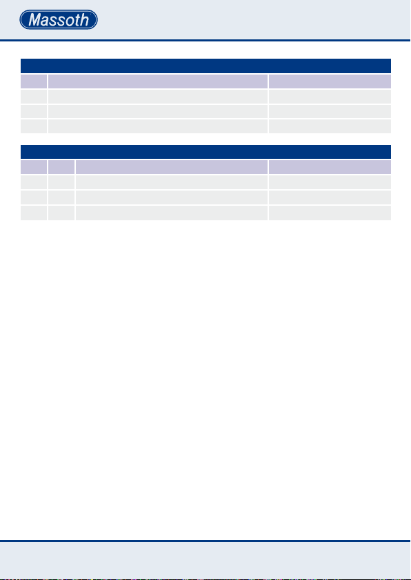
Anhang 1 : CV8 - Resetfunktion
Wert Bereich Bemerkung
11 1, 17, 18, 29, 31, 32, 229, 230 DCC-Grundfunktionen
16 15, 16 Programmiersperre
22 62, 110, 210 Kongurationswerte
Anhang2:CV29:DCC-Konguration
Bit Wert Aus An
0 1 Fahrtrichtung normal Fahrtrichtung invers
1 2 14 Fahrstufen 28 Fahrstufen
5 32 Lokadresse kurz Lokadresse lang
22
Page 23
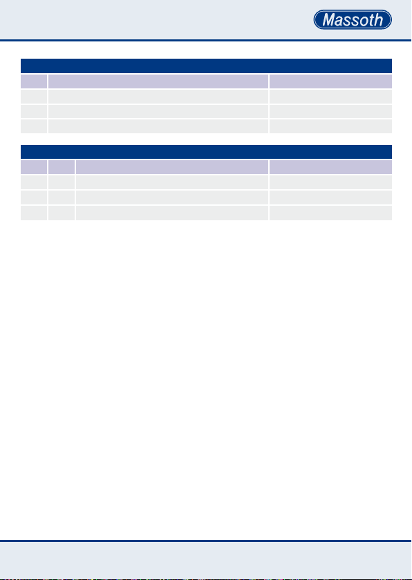
Attachment 1 : CV8 - Reset Function
Value Range Description
11 1, 17, 18, 29, 31, 32, 229, 230 DCC Basic Settings
16 15, 16 Programming Lock
22 62, 110, 210 Conguration Values
Attachment2:CV29:DCCConguration
Bit Value Off On
0 1 Driving Direction Standard Driving direction inverted
1 2 14 Speed Steps 28 Speed Steps
5 32 Loco Address short Loco Address long
23
Page 24

QUALITY
MADE IN
GERMANY
RoHS
COMPLIANT
Massoth Elektronik GmbH
Frankensteiner Str. 28 · D-64342 Seeheim · Germany
FON: +49 (0)6151-35077-0 · FAX: +49 (0)6151-35077-44
eMail: [email protected] · www.massoth.de
032377o
991106 BDA PZB/IR Empfänger 2017.06
 Loading...