

Page 1
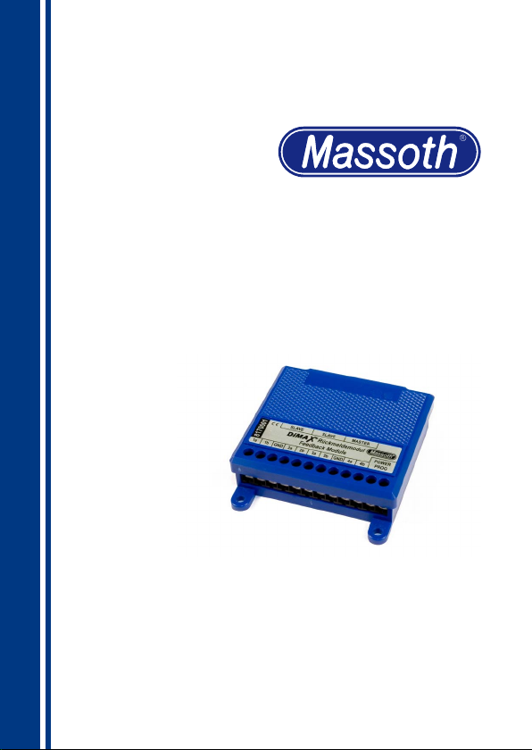
DiMAX Rückmeldemodul (280R)
DiMAX Feedback Module (280R)
Art.-Nr. / Item No.: 8170001
Version 2.0
Page 2

1. Einleitende Informationen
Rückmeldemodule dienen zur
Erkennung von Ereignissen (wie z.B.
die Meldung eines Zuges auf einem bestimmten Gleis oder die Rückmeldung
einer geschalteten Weiche) der Modellbahnanlage. Das Modul überwacht 8
Kontakteingänge auf Änderungen. Bei
einer Schaltänderung an einem Eingang
wird auf dem Bus (oder per Funk) ein
Befehl an die Zentrale gesendet. Dies
kann je nach Programmierung des
Moduls verschiedene Aktionen bewirken. Entweder wird eine Weiche direkt
geschaltet, eine Automatikfunktion in
der DiMAX-Zentrale gestartet oder die
Rückmeldung zu einem PC weitergeleitet. Nach der Auslösung wird der entsprechende Kontakt für eine einstellbare
Zeit gesperrt, um ein mögliches Prellen
(Mehrfachschalten) von Reedschaltern
zu unterdrücken.
Wir empfehlen die Anleitung gründlich
zu lesen, bevor Sie das neue Rückmeldemodul in Betrieb nehmen.
Einige Funktionen sind nur mit der
aktuellsten Firmware nutzbar, führen Sie
bei Bedarf ein Update durch.
1. General Information
The feedback module recognizes events
on model railroad layouts, e.g. the
arrival of a train on a specic track or
the feed back signal of a switch. The
module monitors 8 contact inputs. In
case of a change in the condition of
an input, a command signal is sent to
the central station. This will result in
different actions depending on how the
feedback module was programmed.
E.g., this may throw a switch, it may
start an automated action in the central
station or the signal may be forwarded
to a PC. After triggering, the respective
outlet will be blocked for two seconds
to suppress contact cycling of the reed
relays.
We recommend to read this manual
carefully before the feedback module is
installed and operated.
Some functions require the latest rmware for availability. Please update the
decoder with the latest rmware.
1.1. Funktionsumfang
•Rückmeldemodul mit 8 Kontakteingängen
•Bis zu 4096 Kontaktadressen nutzbar
(bis zu 512 bei LGB® MZS II)
2
1.1. Summary of Functions
•Feedback module with 8 contact
inputs
•Up to 512 (LGB® bus or 4096 (DiMAX
bus) contact numbers usable
Page 3
•Anschluß an Massoth DiMAX-Bus
•Weitere Module durch Master/Slave
•Einfache Einstellung über
•Anschluß von Gleiskontakten
•Funkschnittstelle für kabellose
•Updatemöglichkeit über den
®
oder LGB
Betrieb zusammenschaltbar.
CV-Programmierung
(8420502) und Belegtmeldern
(8170501) möglich.
Rückmeldung in Verbindung mit dem
DiMAX-Funkempfänger
DiMAX-Bus
MZS II-Bus
•Usable on Massoth DiMAX bus or
LGB® MTS II-bus
•Additional modules can be
interconnected in master / slave
operation
•Easy programming by CV setting
•Ready to be connected to the track-
contact (#8420502) or train detection
module (#8170501)
•Equipped with an interface to connect to a DiMAX wireless receiver for
wireless operation
•Update feature via the DiMAX bus
1.2 Lieferumfang
• DiMAX 280R Rückmelder
• Busanschlusskabel
• Handbuch
2. Inbetriebnahme
Bauen sie das Modul an einem
geschützten Platz ein.
Schützen sie es vor Feuchtigkeit sowie
extremen Temperaturschwankungen.
Das Modul darf nur an die in der Anleitung genannte Geräte angeschlossen
werden.
Ein Anschluss an andere Geräte, auch
wenn der Stecker dort passt, kann zur
Zerstörung führen.
Auslieferungszustand: DiMAX-Bus,
ID2(=11), Kontakt 1..4 (a+b)
1.2 Scope of Supply
• DiMAX 280R Feedback Module
• Bus connector cable
• Manual
2. Hook-Up
Install the module in a place that
protects it from moisture and extreme
temperatures.
The module must only be connected to
components that are described in this
manual.
Connecting this unit to other components even if the plugs are matching
may result in serious damage to the
module or other components.
Delivery status: DiMAX-bus,
ID2(=11), Contact 1..4 (a+b)
3
Page 4

2.1. Anschlüsse
2.1 Connectors
2.1.1. Kontakt- und
Schalteingänge
Schalter oder Taster müssen spannungsfrei an das Modul angeschlossen
werden.
Sie dürfen also nicht gleichzeitig von einer anderen Spannung versorgt werden.
Als Gleiskontakt empfehlen wir Massoth
8420502 (Abbild. 1). Dieser wird zwar
auch vom Digitalgleis versorgt, ist aber
am Ausgang galvanisch isoliert.
Bei Nutzung der LGB®-Kontakte 17100
müssen dessen äußeren beiden Klemmen gebrückt werden.
Jedes Schließen des Kontaktes löst
eine Meldung aus. Durch Umprogrammierung auf ‚Pegelsteuerung‘ kann die
nutzbare Kontaktanzahl verdoppelt werden. Beim Schließen des Schalters wird
der a-Kontakt gemeldet, beim Öffnen
der b-Kontakt. Der a-Eingang erhält die
programmierte Adresse, der b-Eingang
erhält die nächsthöhere Adresse. Somit
lassen sich zum Beispiel einfache
Weichenschaltpulte realisieren.
2.1.1 Contact- and Switching
Inputs
Track contacts, switches and push buttons must be connected to the module
zero-potential. IE: they must not be
connected to another power source at
the same time for proper powering up
of that component.
We recommend utilizing Massoth
#8420502 track contacts. It is powered
by the track as well but is equiped with
a galvanically isolated output.
If the LGB® track contact 17100 is used,
both outwards contacts need to be short
circuited.
Every closing of the contact triggers
a signal. The usable contact number
may be doubled by programming the
module to level control (only DiMAX
bus). In case the reed switch is closed
the “a” contact is reported. In case the
reed relay is released the “b” contact
is reported. The “a” contact has the
programmed address; the “b” contact
has the next higher address. With this
method simple switch control panels
may be built.
4
Page 5
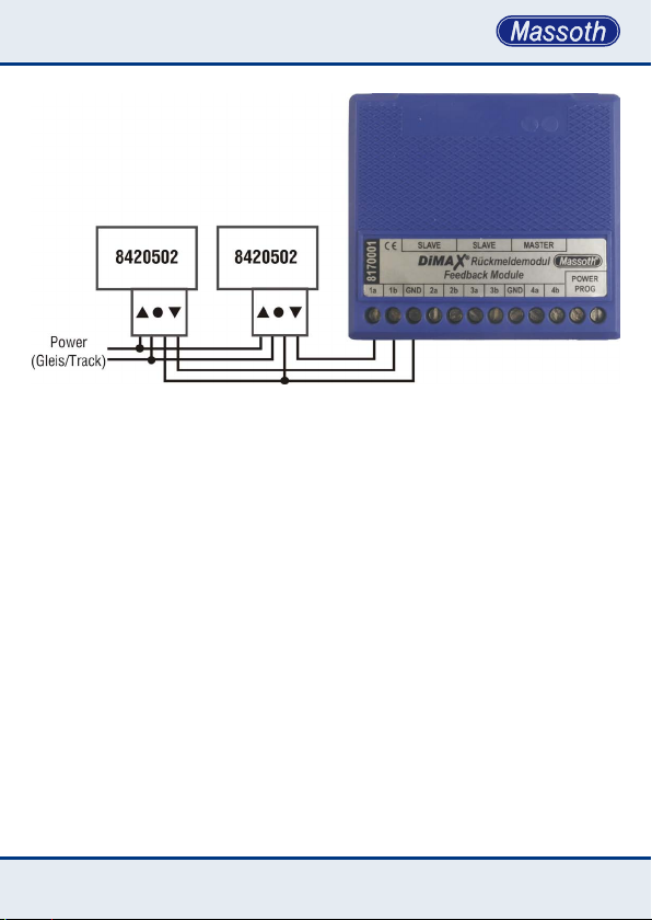
Abbildung 1: Kontakt und Schalteingänge
Illustration #1: Contact and Switching Input
2.1.2. Busanschluss
Der Rückmelder kann mit dem beiliegenden Buskabel direkt an eine DiMAX
oder LGB®-Zentrale angeschlossen
werden. DiMAX oder LGB®-Bus werden
über CV 1..3 eingestellt.
ACHTUNG : Die Buchsen für Bus
(Master/Slave) dürfen auf keinen Fall
vertauscht werden ! (Abb. 2)
2.1.2 Bus Connection
Using the provided bus cable the
feedback module may be connected
directly to a DiMAX or LGB® MTS
central station. DiMAX or LGB® bus will
be congured with CV 1..3.
NOTE: The terminals for bus (master/
slave) must not be mixed up.
(Illustr. #2)
5
Page 6
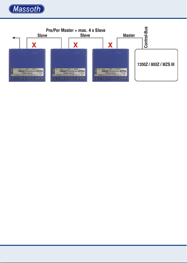
Abbildung 2: Busanschluss
Illustration #2: Bus connection
2.1.3. Master- / Slaveanschluss
Zur einfacheren Verkabelung können bis
zu 4 Module gemeinsam als ‚Slave‘ an
einem ‚Master‘ betrieben werden. Diese
senden ihre Daten, ohne dass sie eine
eigene ID benötigen, an den Master,
welcher unter seiner ID-Nummer die
Befehle an die Zentrale weiterleitet. An
den Slavebus können auch LGB® 55070
Rückmelder angeschlossen werden.
(CV 3=5)
Ebenso kann dieses Modul als Slave
an einem LGB® 55070 angeschlossen
werden. (CV 1≠0)
2.1.4. Funkbetrieb
Der Einbau des DiMAX Rückmeldesenders 8133701 (EU) oder 8132701
(US) ist vorbereitet und ab Firmware
V2.0 nutzbar. Die Daten werden von
dem Rückmelder per Funk zu einem
Empfänger gesendet werden. Auch
6
2.1.3. Master / Slave Operation
Up to four modules may be operated as
slaves at the same time in connection
with a master unit. The slave modules
send their data to the master unit. They
do not need an ID. The master uses
its ID to relay the commands from the
slaves to the central station. The slave
bus allows mixed operation with LGB®
55070 feedback modules. (CV 3=5)
You can also connect this module as
slave with LGB® 55070. (CV 1≠0)
2.1.4. R/C operation
The DiMAX feedback module is ready to
be retrotted with the wireless DiMAX
feedback transmitter 8133701 (EU
band) or 8132701 (US band). Firmware
V2.0 is required. All the feedback data
is transmitted to the assigned receiver.
Page 7
von angeschlossenen ‚Slave‘ Modulen
werden die Daten per Funk übertragen.
Zur Versorgung des Rückmelders wird
dann eine zusätzliche Spannungsversorgung von 10..24V AC benötigt. (z.B.
Gleisspannung).
The data from the connected slave modules will be transmitted as well. For the
wireless operation the feedback module
requires an additional power source of
10…24 Volts AC (e.g. track power).
2.2. Funktionsarten
(nur für DiMAX-Bus)
Programmierung der Funktionsarten
siehe Anhang 2.
2.2.1. Flankensteuerung
Jedes Schließen eines Kontaktes löst
den zugehörigen Befehl aus. Das Öffnen
hat keine Auswirkung.
2.2.2. Pegelsteuerung
Jedes schließen eines Kontakts löst
einen „a-Befehl“ aus. Jedes öffnen einen
„b-Befehl“. Der zugehörige „b-Eingang“
arbeitet automatisch auf der Adresse +1
(z.B. bei Adresse 10 ist der „b-Eingang“
11). Mit dieser Funktion lassen sich einfache Weichenschaltpulte für 8 Weichen
pro Modul realisieren. Auch einfache
Gleisbelegtmelder ohne Spannungserkennung sind so möglich.
Beispiel: Eingang „1a“ sendet „1a“
beim Schließen und „1b“ beim Öffnen.
Der zugehörige Eingang „1b“ sendet
„2a“ beim Schließen und „2b“ beim
Öffnen.
2.2. Types of Function
(DiMAX bus only)
For programming the types of function
see attachment 2.
2.2.1. Flank Control
A command is released every time
a contact is closed. On opening the
contact no action is triggered.
2.2.2. Level Control
Every time a contact closes an “a-command” is triggered. Every time a contact
opens, a “b-command” is released.
The associated “b-input” works
automatically on address +1 (e.g. if the
address is 10, the b-input is on address
11). This function facilitates an easy
setup for a switch control board for 8
switches per module. Thus a simple
type train detection can be set up.
For example: output 1a sends “1a”
when the contact closes and “1b” on
opening. The respective contact „1b“
sends „2a“ when closed and „2b“
when opened.
7
Page 8

2.2.3. Richtungsabhängige
Auslösung
Wenn man 2 Gleiskontakte hintereinander anordnet, kann die Fahrtrichtung
gemeldet werden. Erst Auslösung „b“
und danach „a“ sendet „a“ für die eine
Richtung. Wenn Auslösung „a“ und
danach „b“ sendet „b“ für die entgegengesetzte Fahrtrichtung.
2.2.3. Direction Sensitive
Triggering
The driving direction may be detected if
two reed contacts are positioned one af-
ter another. In case “b” is triggered rst
and thereafter “a”, an “a” is sent for the
driving direction. In case “a” is triggered
rst and “b” thereafter, a “b” is sent for
the opposite driving direction.
2.2.4. Belegtmeldemodus
(Anschluss von 8170501)
An Eingang „a“ wird die Belegterkennung angeschlossen.
Ist der Gleis belegt = Gleiskontakt
geschlossen = „a-Befehl“
Ist der Gleis frei = Gleiskontakt offen =
„b-Befehl“
Am Eingang „b“ wird die Spannungserkennung angeschlossen.
Ist eine Gleisspannung vorhanden
werden die Daten vom „a-Eingang“
gesendet.
Ist keine Gleisspannung vorhanden
werden auch keine Daten vom
„a-Eingang“ gesendet. (Z.B. Notaus)
3. Einstellungen und
Programmierung
Das Rückmeldemodul wird wie ein
Dekoder auf dem Programmiergleis
eingestellt. Mögliche Programmierarten
sind CV-Programmieren, CV-Lesen
und Register-Programmieren. Somit
8
2.2.4. Train Detection Mode
(Connection from 8170501)
The train detection module must be
connected to input “a”.
In case the track section is occupied =
the track contact is closed, an “a” signal
is given out.
In case the track section is clear = the
track contact is open, a “b” signal is
given out.
Input “b” is connected to the voltage
recognition.
If track voltage is detected data are
transmitted from output “a”.
If no track voltage is detected no data
are transmitted from output “a”. (E.g.
emergency stop)
3. Settings and Programming
The DiMAX feedback module must
be programmed like a decoder on the
programming track. Possible programming procedures are: CV writing, CV
reading, and register programming. This
Page 9
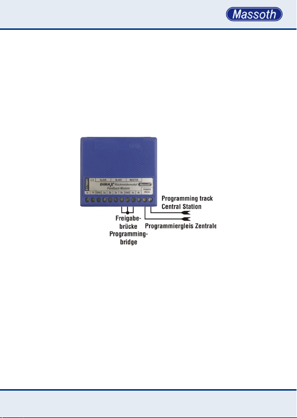
kann auch mit älteren LGB
eine Programmierung durchgeführt
werden. Zum Programmieren muss eine
Kabelbrücke zur Freigabe angeschlossen werden (Abb. 3) oder eine Freigabe
über CV 6=77 erfolgen und kann nur
durchgeführt werden, wenn die Busverbindung nicht besteht. Ist das Buskabel
®
-Geräten
facilitates a programming of older LGB®
components. For programming a short
circuiting bridge must be installed (see
illustr. #3) or a programming approval
needs to be set in CV 6=77 which can
only be used, if the bus connection is
not plugged in. If the Bus-Cable is con-
nected programming is not possible.
angeschlossen ist eine Programmierung
nicht möglich.
Abbildung 3: Programmiermodus mit Freigabebrücke
Illustration #3: Programming mode with programming bridge
3.1. Programmierung für
LGB®-MZS
Für einen Betrieb am LGB® MZS-Bus
sind nur 2 Einstellungen nötig. Es sind
maximal 512 Kontakte (256 Kontaktnummern mit je zwei Richtungen
nutzbar)
3.1. Programming with LGB® MTS
Operation with the LGB® bus system
requires the setting of only two (2)
CVs. A maximum of 512 contacts may
be utilized (256 contact numbers in 2
directions).
9
Page 10

Kontaktnummer (CV 1):
• Nummer des ersten Kontaktpaares
(die restlichen 3 Kontakte werden
automatisch nummeriert).
• Die Programmierung erfolgt in 4er
Schritten (z.B. 1 = Kontakt 1..4 ,
5 = Kontakt 5..8 , ... )
• Jeweils 2 Kontakte bilden eine Gruppe
und nutzen eine gemeinsame Nummer
mit den Zusätzen a+b.
• Die ersten 128 Nummern können zum
direkten Weichen schalten genutzt
werden. (z.B. 7 = Weiche 7)
• Die weiteren Kontakte (129-256)
können für eine PC-Steuerung genutzt
werden.
ID-Nummer LGB
®
Bus (CV 2):
• Jedes Gerät am LGB®-Bus benötigt
eine ID-Nummer, um Daten auf den
Bus senden zu können.
• ID-Nummern sollten nicht doppelt
genutzt werden, dies könnte zu
Störungen führen.
• Wenn die zulässigen Nummern (1..7)
nicht reichen, kann man weitere
Module als Slave anschließen.
CV 1 contact #:
• Dene the number of the rst contact
pair. (a numbering of the remaining
contact will occur automatically).
• Programming is done in groups of
four (e.g. 1= contacts 1 .. 4, 5 = 5 .. 8)
• Two contacts are considered a group
which uses a common number with
the extensions a+b
• The rst 128 numbers may be used to
control switches directly
(e.g. 7 = switch #7)
• The contacts 129 to 256 may be
utilized in connection with a PC
controlled program
CV 2 : ID# LGB® bus
• Each component working on the LGB®
bus requires an ID number in order to
be authorized to send data to the bus.
• ID numbers should be used only once.
Multiple use of the same ID number
will cause a malfunction.
• In case the ID numbers 1 .. 7 are not
sufcient further modules may be
utilized as slaves.
3.2. Programmierung für DiMAX
Für die Nutzung des Moduls an DiMAXZentralen stehen vielfältige Einstellungen zur Auswahl. Die einzelnen
Programmierwerte entnehmen sie bitte
der anhängenden CV-Liste. (CV 1=0!)
10
3.2. Programming for DiMAX
Using the DiMAX feedback module in
connection with DiMAX central stations
various settings are at hand. For the
respective programming values please
check the attached CV list. (CV 1=0!)
Page 11
ID-Nummer (CV 2):
• Jedes Gerät am DiMAX-Bus muss eine
eigene ID-Nummer (11..20) haben!
• Eine Doppelbelegung ist nicht zulässig
und führt zu Störungen.
ID # (CV 2):
• Each component on the DiMAX bus
must have its own ID # (11..-20).
• Multiple use of the same ID # will
cause a malfunction.
Kontaktadresse (CV 51+52 , 61+62 ,
71+72 , 81+82):
• Es kann für jedes Kontaktpaar eine
eigene freie Kontaktnummer programmiert werden.
• Es können Kontaktadressen von 1 bis
2048 programmiert werden.
Zeitverzögerung (CV 53+54 , 63+64 ,
73+74 , 83+84):
• Ein ausgelöster Kontakt kann damit
zeitverzögert an die Zentrale gesendet
werden.
Beispiel : Ein Zug löst den Kontakt
aus.
Nach 10 Sekunden wird hierdurch eine
Weiche geschaltet.
Wird während der Wartezeit erneut
ausgelöst, so wird die Wartezeit neu
gestartet.
Konguration (CV 55 , 65 , 75 , 85):
• siehe Anhang 2
• Erweiterung zum Anschluss von
Belegtmeldern oder Nutzung von
richtungsabhängigen Auslösungen
Contact Addresses (CV 51+52, 61+62,
71+72, 81+82):
• Every contact pair may be programmed with it s own contact
number.
• You may use contact addresses from
1 to 2048.
Time Delay (CV 53+54, 63+64, 73+74,
83+84):
• A closed contact may be sent to the
central station after a time delay.
Example: a train triggers a contact and
10 seconds later a switch is thrown.
If the contact is triggered during the
delay time, the delay time is restarted
Conguration (CV55, 65, 75, 85):
• see attachment 2
• Connecting the train detection module
or handling of direction dependant
trigger signals
11
Page 12

3.3. Rücksetzen auf
Auslieferungszustand
Durch Programmieren des Wertes 55
in CV 7 kann der Dekoder auf seinen
Auslieferungszustand zurückgesetzt
werden.
3.3. Reset to Manufacturers
Default Settings
A reset to the manufacturer’s basic setting may be accomplished by setting
CV 7 to value “55”.
3.4. Firmwareupdate
Das Modul kann jederzeit durch ein
Firmwareupdate auf den neuesten
Stand gebracht werden. Somit können
auch zukünftige Funktionen genutzt
werden. Zum Update schließen sie den
Busanschluss des Moduls mit dem
beiliegenden Buskabel an eine DiMAXZentrale oder das DiMAX PC-Modul an.
Es darf immer nur ein einzelnes Gerät
zum Update angeschlossen werden.
Weitere Informationen zum Update
nden sie in der Bedienungsanleitung
des jeweiligen Gerätes.
3.4. Firmware Update
The DiMAX Feedback Module may be
updated at any time. This ensures easy
usage of future functions. For updating,
the DiMAX Feedback Module must be
connected to a DiMAX central station
or the PC Module utilizing the provided
bus cable. Only one single component
should be connected to the central station during an update. Please check the
manual of your DiMAX central station or
the PC Module for further instructions.
12
Page 13
13
Page 14
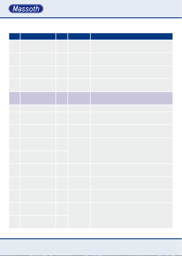
3.5. CV-Werte
CV Beschreibung Def. Bereich Bemerkung
1 Kontaktnummer 0
2 ID-Nummer 11
0, 1 ..
1..7 +
11..20
3 Bustyp 1 1, 2, 5
6 Prog.-freigabe 77 0 + 77
7 Resetfunktion --- 55
Nur für LGB
9, 13, ... , 249, 253) 0 = DiMAX
253
1..7 für LGB
11..20 für DiMAX-Busanschluss
1 = Master , 2 = Slave,
5= Master für LGB
0 = Programmierung gesperrt,
77 = Programmierung freigeben
Rücksetzen aller Werte auf Ausliefe-
rungszustand
7 Softwareversion 20 --- Version 2.0
Hersteller-
8
kennung
50 Entprellzeit 20 1 .. 20
51 Kontaktnr. 1a+b 0
52 Kontaktnr. 1a+b 1
Zeitverzögerung
53
1a
Zeitverzögerung
54
1b
Konguration
55
1 a+b
61 Kontaktnr. 2a+b 0
62 Kontaktnr. 2a+b 2
123 --- Hersteller : Massoth
Kontaktsperrzeit nach Auslösung
(Entprellung) 0,1 .. 2,0 Sekunden
CV 51 = hohes Byte der Adresse,
1 .. 2048
CV 52 = tiefes Byte der Adresse
Im Anhang 1 nden sie die Berechnung
der beiden CV‘s
0 1 .. 100
0 1 .. 100
Zeitwert in Sekunden, ob der Kontakt
verzögert zurückgemeldet wird
Zeitwert in Sekunden, ob der Kontakt
verzögert zurückgemeldet wird
0 0 ... 7 Siehe Anhang 2
CV 61 = hohes Byte der Adresse,
1 .. 2048
CV 62 = tiefes Byte der Adresse
Im Anhang 1 nden sie die Berechnung
der beiden CV‘s
®
-MZS in 4er Schritten (1, 5,
®
-Busanschluss,
®
-Slaves
14
Page 15
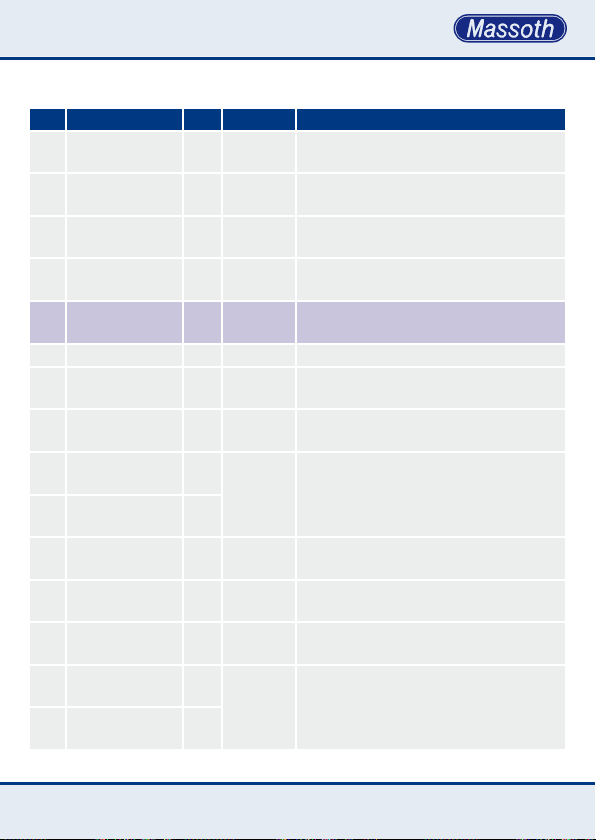
3.5. CV-Settings
CV Description Def. Value Note
1 contact number 0
2 ID number 11
0, 1 ..
1..7 +
11..20
3 bustype 1 1, 2, 5
6 prog.-clearance 77 0 + 77
Only for LGB
9, 13, …249, 253) 0 = DiMAX
253
1..7 for MTS bus,
11..20 for DiMAX bus
1 = Master , 2 = Slave,
5= Master for LGB
0 = programming disabled,
77 = programming enabled
7 reset function --- 55 Reset to manufacturer setting
7 software version 20 --- version 2.0, read only
8 manufacturer ID 123 --- manufacturer: Massoth, read only
50 debounce time 20 1 .. 20
51 contact no. 1a+b 0
1 .. 2048
52 contact no. 1a+b 1
contact blocking time after trigger
(debounce) 0,1 .. 2,0 Seconds
CV 51=high byte of the address,
CV 52=low byte of the address
Computation of the CVs is shown in
attachment 1
53 time delay 1a 0 1 .. 100 delay of the feedback signal in secs
54 time delay 1b 0 1 .. 100 delay of the feedback signal in secs
conguration
55
1 a+b
61 contact no. 2a+b 0
62 contact no. 2a+b 2
0 0 ... 7 See attachment 2
CV 61=high byte of the address,
1 .. 2048
CV 62=low byte of the address
Computation of the CVs is shown in
attachment 1
®
MTS in steps of 4: (1, 5,
®
-slaves
15
Page 16
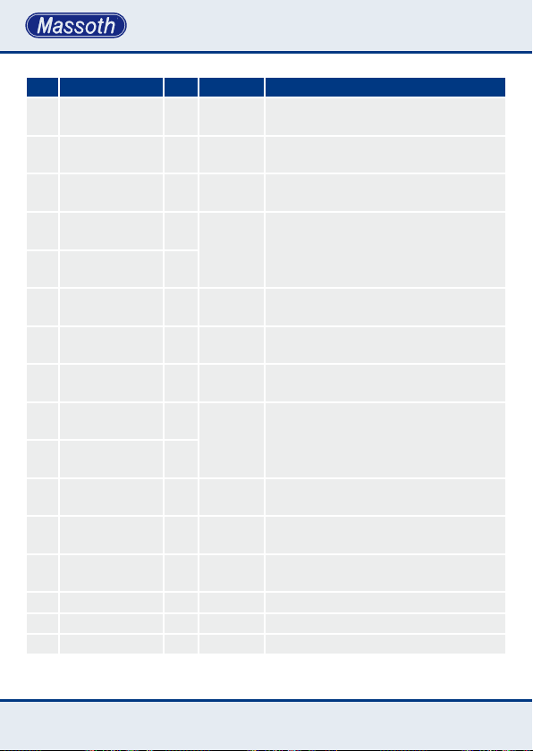
CV Beschreibung Def. Bereich Bemerkung
Zeitverzögerung
63
2a
Zeitverzögerung
64
2b
Konguration
65
2 a+b
71 Kontaktnr. 3a+b 0
72 Kontaktnr. 3a+b 3
Zeitverzögerung
73
3a
Zeitverzögerung
74
3b
Konguration
75
3 a+b
81 Kontaktnr. 4a+b 0
82 Kontaktnr. 4a+b 4
Zeitverzögerung
83
4a
Zeitverzögerung
84
4b
Konguration
85
4 a+b
100 Funk-Band 0 0 + 1 0 = EU, 1 = US
101 Funk-Kanal 1 1 .. 4 Kanalwahl 1 .. 4
102 Funk-ID 4 1 .. 8 ID-Gerätenummer 1 .. 8
0 1 .. 100
0 1 .. 100
0 0 ... 7 Siehe Anhang 2
1 .. 2048
0 1 .. 100
0 1 .. 100
0 0 ... 7 Siehe Anhang 2
1 .. 2048
0 1 .. 100
0 1 .. 100
0 0 ... 7 Siehe Anhang 2
Zeitwert in Sekunden, ob der Kontakt
verzögert zurückgemeldet wird
Zeitwert in Sekunden, ob der Kontakt
verzögert zurückgemeldet wird
CV 71 = hohes Byte der Adresse,
CV 72 = tiefes Byte der Adresse.
Im Anhang 1 nden sie die Berechnung
der beiden CV‘s
Zeitwert in Sekunden, ob der Kontakt
verzögert zurückgemeldet wird
Zeitwert in Sekunden, ob der Kontakt
verzögert zurückgemeldet wird
CV 81 = hohes Byte der Adresse,
CV 82 = tiefes Byte der Adresse
Im Anhang 1 nden sie die Berechnung
der beiden CV‘s
Zeitwert in Sekunden, ob der Kontakt
verzögert zurückgemeldet wird
Zeitwert in Sekunden, ob der Kontakt
verzögert zurückgemeldet wird
16
Page 17
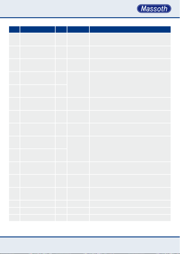
CV Description Def. Value Note
63 time delay 2a 0 1 .. 100 delay of the feedback signal in secs
64 time delay 2b 0 1 .. 100 delay of the feedback signal in secs
conguration
65
2 a+b
71 contact no. 3a+b 0
72 contact no. 3a+b 3
73 time delay 3a 0 1 .. 100 delay of the feedback signal in secs
74 time delay 3b 0 1 .. 100 delay of the feedback signal in secs
conguration
75
3 a+b
81 contact no. 4a+b 0
82 contact no. 4a+b 4
83 time delay 4a 0 1 .. 100 delay of the feedback signal in secs
84 time delay 4a 0 1 .. 100 delay of the feedback signal in secs
conguration
85
4 a+b
100 RC-waveband 0 0 + 1 0 = EU, 1 = US
101 RC-channel 1 1 .. 4 channel selection 1 .. 4
102 RC-ID 4 1 .. 8 ID-number 1 .. 8
0 0 ... 7 See attachment 2
CV 71=high byte of the address,
1 .. 2048
0 0 ... 7 See attachment 2
1 .. 2048
0 0 ... 7 See attachment 2
CV 72=low byte of the address
Computation of the CVs is shown in
attachment 1
CV 81=high byte of the address,
CV 82=low byte of the address
Computation of the CVs is shown in
attachment 1
17
Page 18

Anhang 1: Berechnung der
Kontaktadressen
CV 51 = Kontaktnummer / 256
(Ganzzahliges Ergebnis ohne Kommastellen speichern).
CV 52 = Kontaktnummer - (CV 51 x
256)
Die Berechnung gilt genauso für
CV 61+62, 71+72 sowie 81+82.
Ein Beispiel für Adresse 735:
735/256 = 2,87 also CV 51 = 2
735 - (2 x 256)= 223 also CV 52 = 223
Attachment 1: Computation of the
contact addresses
CV 51= contact # / 256
(store the whole numbered result without decimal place)
CV 52= contact # - (CV 51 x 256);
the computation works the same for
CV 61+62, 71+72, and 81+82
This is an example for address 735:
735 / 256 = 287 This means CV 51= 2
735 – (2 x 256) = 223 This means
CV 52= 223
Anhang2:Kongurationsregister
CV 55 , 65 , 75 , 85
0 = Rückmeldebefehl
(über Schaltanke)
1 = Weichenbefehl (über Schaltanke)
2 = Rückmeldebefehl
(über Pegelsteurung)
3 = Weichenbefehl
(über Pegelsteuerung als Schaltpult)
4 = Rückmeldebefehl
(Richtungsabhängig)
5 = Weichenbefehl (Richtungsabhängig)
6 = Belegtmeldemodus
18
Attachment2:CongurationRegister CV 55 , 65 , 75 , 85
0 = feedback command
(over ank control)
1 = switch command
(over ank control)
2 = feedback command
(over level control)
3 = switch command
(over level control as switchboard)
4 = feedback command
(direction sensitive triggering)
5 = switch command
(depending on orientation)
6 = train detection mode
Page 19
5. Technische Daten
Spannung:
• automatische Versorgung durch das
DiMAX-Buskabel oder LGB®-Buskabel
• Im Funkbetrieb : 10 .. 24V DC/DCC
oder 12 .. 18V AC an ‚Power‘
Anschluss
• DCC-Programmierspannung an
‚Power‘ Anschluss : 12 .. 24V 0-24 V
Stromaufnahme:
• ca. 30mA (ca. 50mA im Funkbetrieb).
• 100..250mA Antwortstrom zur
Programmierbestätigung.
Temperaturbereich: -20 - +45°C
Abmessungen: 80 x 70 x 20 mm
(L x B x H)
Hinweis zur Temperatur: Um Kondenswasserbildung zu vermeiden benutzen
Sie die Elektronik bei Temperaturen
unter 0°C nur, wenn diese vorher aus
einem beheizten Raum kommt. Die
Eigenwärme des Fahrbetriebs reicht
aus um Kondenswasserbildung zu
verhindern.
5.TechnicalSpecications
Power Supply:
• Automatic power supply by the DiMAX
bus cable or LGB® bus cable
• During wireless operation: 10…24 Volt
DC / DCC or 12…18 Volt AC at power
terminal
• DCC programming power at power
terminal 12…24 Volt
Current:
• About 30 mAmp (about 50 mAmp in
wireless operation)
• 100…250 mAmp during programming
30-2000 mAmps
Temperature Range: -4°F to +113°F
Measurements: 80 x 70 x 20 mm
(L x W x H)
Note: If you intend to utilize this decoder
below freezing temperatures, make sure
it was stored before in a heated environment before operation to prevent the
generation of condensed water. The heat
generated during operation is sufcient
to prevent condensed water.
19
Page 20

5.1 Garantie, Reparatur,
Kundendienst
MASSOTH gewährt die Fehlerfreiheit
dieses Produkts für ein Jahr. Die
gesetzlichen Regelungen können in
einzelnen Ländern abweichen.
Verschleißteile sind von der
Garantieleistung ausgeschlossen.
Berechtigte Beanstandungen werden
kostenlos behoben. Für Reparatur- oder
Serviceleistungen übergeben Sie das
Produkt bitte Ihrem Fachhändler oder
senden es direkt an den Hersteller.
Unfrei zurückgesendete Sendungen
werden nicht angenommen. Eine Kopie
des Kaufbelegs wird vorausgesetzt. Für
Schäden durch unsachgemäße
Behandlung oder Fremdeingriff oder
Veränderung des Produkts besteht kein
Garantieanspruch. Der Anspruch auf
Serviceleistungen erlischt unwiderruflich. Irrtümer und Änderungen vorbehal-
ten. Auf unserer Internetseite nden Sie
die jeweils aktuellen Broschüren,
Produktinformationen, Dokumentation
und Softwareprodukte rund um
MASSOTH-Produkte.
5.1 Warranty, Service, Support
MASSOTH warrants this product against
defects in materials and workmanship
for one year from the original date of
purchase. Other countries might have
different legal warranty situations.
Normal wear and tear, consumer modi-
cations as well as improper use or
installation are not covered. Peripheral
component damage is not covered by
this warranty. Valid warranty claims will
be serviced without charge within the
warranty period. For warranty service
please return the product to you dealer
or send it directly to the manufacturer.
Return shipping charges are not covered by MASSOTH. Please include your
proof of purchase with the returned
goods.
Errors and changes excepted.
Please check our web site for up to
date brochures, product information,
documentation and software updates.
20
Page 21
21
Page 22

22
Page 23
5.2 Hotline
Serviceanfragen richten Sie bitte an:
5.2 Hotline
For technical support contact:
Massoth Elektronik GmbH
Mo 14:00-17:30 sowie Do 8:00-12:00
FON +49 (0)6151-35077-38
FAX +49 (0)6151-35077-44
[email protected]
Dieses Produkt entspricht den CE Konformitätsrichtlinien für elektrische Kleingeräte in der aktuellen Fassung.
This unit conforms to the CE Standards
Dieses Produkt ist nach den aktuellen EG Richtlinien umgangssprachlich „bleifrei“ hergestellt und damit RoHS-konform.
RoHS
COMPLIANT
This unit is manufactured according to the latest EG Standards for lead free
manufacturing conforming to RoHS Standard.
032377o
Entsorgen Sie das Produkt nicht im Hausmüll. Nutzen Sie bitte den dafür
vorgesehenen Elektroschrott.
Please dispose of according to your State regulations.
Werfen Sie das Produkt nicht in offenes Feuer oder durch Hitze entammbare
Brennstoffe.
Do not dispose of in open re.
Massoth Elektronik GmbH, Germany
Mo 2:00-5:30 p.m. Thu 8:00-12:00 a.m.
FON +49 (0)6151-35077-38
FAX +49 (0)6151-35077-44
[email protected]
Massoth Electronics USA
6585 Remington Dr. Suite 200
Cumming, GA 30040
9:00 a.m. to 4:00 p.m. EST Mo thru Fr
Ph. +1 770-886-6670
Fax +1 770-889-6837
[email protected]
23
Page 24

MADE
IN
GERMANY
Massoth Elektronik GmbH
Frankensteiner Str. 28 · D-64342 Seeheim · Germany
FON: +49 (0)6151-35077-0 · FAX: +49 (0)6151-35077-44
eMail: [email protected] · www.massoth.de
8170001_0510_ML
 Loading...