

Page 1

BLUELINE
FLATLINE II
12 CHANNEL HI-LEVEL TO RCA SU MM IN G CO NV ERT OR
Page 2

1 INTRODUCTION.
2. FEAT UR ES :
Thank yo u for pu r c h a s i n g the MASS I VE BLUELINE/FLATLI N E I I , A
twelve- channel h i g h p e r f o rmance audi o s i g n a l p r ocess o r. These
unique pro d u c t s w i l l a ccept two, f o u r , s i x , e i ght or twelve
channels o f S p e a k e r H i -Level signal fro m a n O E M s o u r ce unit and
will conve rt it to a high-q uali t y , Low n o i s e p r e - amp signal . N o w you
own an ideal i n t e r fa c e c omponent wh i c h w i l l a l low yo u t o u se yo u r
OEM source u n i t a n d e n j o y b e tter music ex p e r i e n c e Ac h i e va b l e by
the af t e r m a r k et amplifie r ( s ) a n d p r ocess o r(s). MASSIVE product s
are the resu lt of adva n c e d c raf t s m anship whic h u s e s t h e h i ghest
quality compone n t s a n d s t r ict quality contr o l s ta n d a r d s i n o rder
to provide you with a long j oyful list e n i n g j o u r ney. Pleas e r e a d
this manual thoro u g h ly to ensu r e t h at yo u g e t t h e max imum benefi t
from this ne w c o m p o n e n t. Proper ins ta l l ation will he l p e n s u r e
years of tro u b l e - f r e e performan c e .
It is recomm e n d e d t h at yo u h av e o u r p r o d u c t installed by a n
authoriz e d M ASSIVE re ta i l e r . H owever, if you decide to in s ta l l i t
yo u r s e lf, please carefu l ly read thro u g h t h i s m a nua l and take your
time for a careful in s ta l l ation.
D/A conv e rter with D/A sa m p l i n g 4 4 . 1 K H z
Conne c t p h o n e o r p o rtable devic e v i a B l uetoo t h ® f o r m u s i c p l ay b a c k
(Blueline)
3. SPECIFICATI ON S
Page 3

1
1 INTRODUCTION.
2. FEAT UR ES :
Thank yo u for pu r c h a s i n g the MASS I VE BLUELINE/FLATLI N E I I , A
twelve- channel h i g h p e r f o rmance audi o s i g n a l p r ocess o r. These
unique pro d u c t s w i l l a ccept two, f o u r , s i x , e i ght or twelve
channels o f S p e a k e r H i -Level signal fro m a n O E M s o u r ce unit and
will conve rt it to a high-q uali t y , Low n o i s e p r e - amp signal . N o w you
own an ideal i n t e r fa c e c omponent wh i c h w i l l a l low yo u t o u se yo u r
OEM source u n i t a n d e n j o y b e tter music ex p e r i e n c e Ac h i e va b l e by
the af t e r m a r k et amplifie r ( s ) a n d p r ocess o r(s). MASSIVE product s
are the resu lt of adva n c e d c raf t s m anship whic h u s e s t h e h i ghest
quality compone n t s a n d s t r ict quality contr o l s ta n d a r d s i n o rder
to provide you with a long j oyful list e n i n g j o u r ney. Pleas e r e a d
this manual thoro u g h ly to ens u r e t h at yo u g e t t h e max imum benefi t
from this ne w c o m p o n e n t. Proper in s ta l l ation will he l p e n s u r e
years of trou b l e - f r e e performan c e .
It is recomm e n d e d t h at yo u h av e o u r p r o d u c t installed by a n
authoriz e d M ASSIVE re ta i l e r . H owever, if you decide to in s ta l l i t
yo u r s e lf, please carefu l ly read thro u g h t h i s m a nua l and take your
time for a careful in s ta l l ation.
D/A conv e rter with D/A sa m p l i n g 4 4 . 1 K H z
Conne c t p h o n e o r p o rtable devic e v i a B l uetoo t h ® f o r m u s i c p l ay b a c k
(Blueline)
Au t o m at i c p r i o r i t y pa i r i n g a n d i n t e lligent connectio n f u n c t i o n
(Blueline)
Two summ i n g n e t w o r k g r o u p s for full control of fro n t a n d r e a r
channe l s
Au t o m u s i c s e n sing turn on/off with r e m o t e o u t
Ad j u s ta b l e o u t p u t l e v e l s
Bluetooth® mod u l e a u t o t u r n o n / o f f function (Blueline)
Synchr o n o u s R e mote Outp ut for controlling af termarket e q u i p m e n t
3. SPECIFICATI ON S
No. of Chann e l s : 1 2
Inpu t Leve l : 5 0 m V ~ 3 5 V
Gain ra n g e: - 14dB ~ 0dB
Power supp ly: PWM S w i tching P o w e r R e g u l ator
Wo r k i n g Voltage Ra n g e: 8.2 ~ 16V DC
Standby c u r r e nt:<8 mA
Wo r k i n g C urrent: 0.2A <
Re commended f u s e val u e s:1 A
Sampling Frequency : 44.1K Hz(On ly for BLUELINE)
Wi r e l e s s t ransmission ra nge: >10m ( Bl u e t ooth SIG) ( only for
BLUELINE )
Blue t o o t h O p e rat ing Fr e q u e ncy : 2 . 4 - 2.48GHz ( only for
BLUELINE )
Re ceiver Sens i t i v i t y : < -80dbm ( only for )BLUELINE
Maximum outp u t l e v e l >4.8V RMS (1K H z 1 % T H D ) e a c h channel
S/N Ratio: >105 dB
THD+N: < 0.0 5 % ( 1 K H z , r e ferred to 3V ou t p u t )
BLU ELINE/FLATLINE II
Built- i n h igh quality A u d i o d ecoder
Page 4
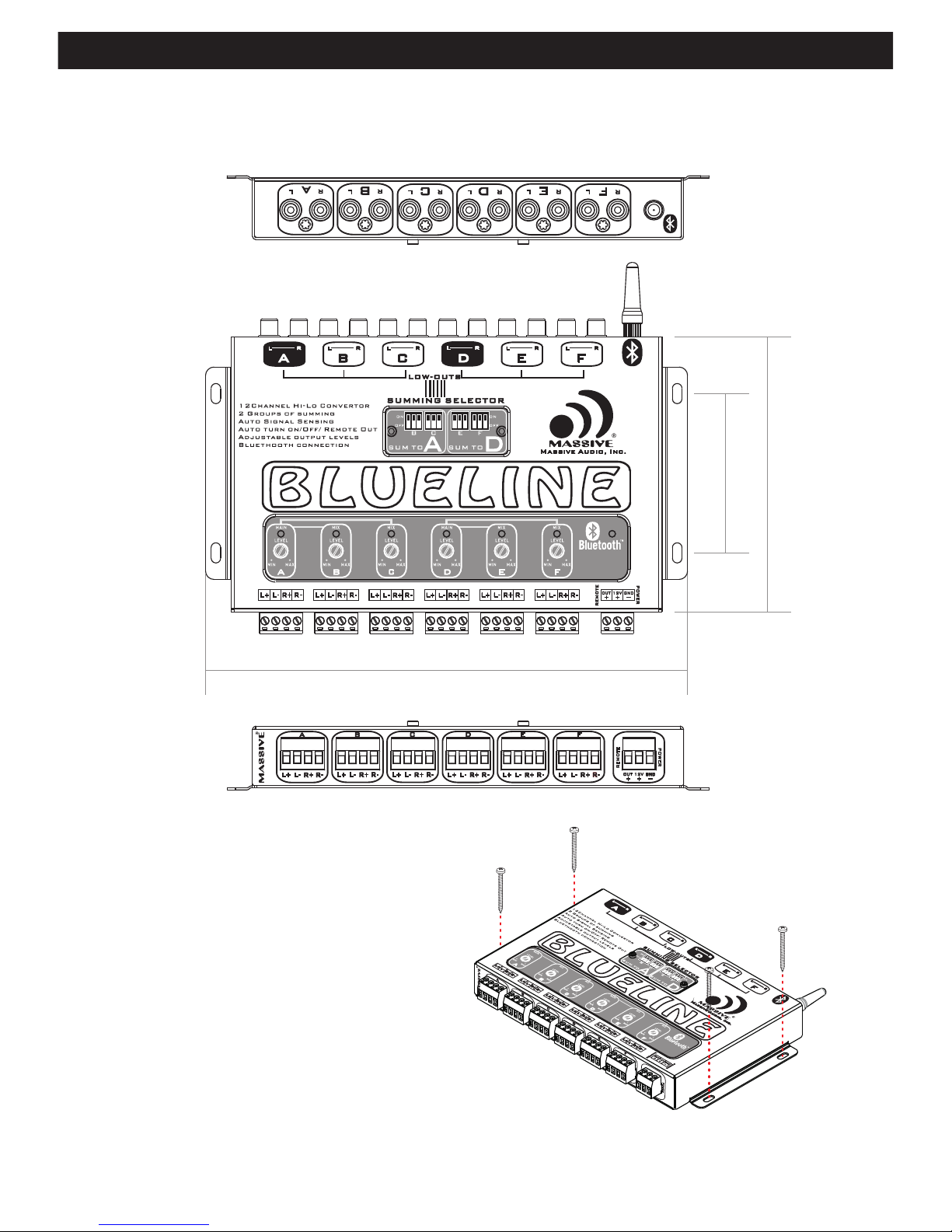
5A :Connectio n i n t e r fa ce function
5B 4 Pin Terminals: C o n n e c t t o t h e OEM source un i t h i g h l e v el
signal out p u t t erminals .
5D Signal in p u t : R e m o t e control out p u t a nd power supp ly
(1) Hi g h leve l s ign a l i np u t
Connect the fa c t o ry- in s ta l l e d O EM source uni t a u d i o o u t put
terminal s t o t h e h i g h l e vel signal in p u t terminals o f B LUE L I N E /
FLATLINE II ; Inp u t s e nsitivity a d j u s ta b le from 50mV t o 3 5 V.
(2) Po w er sup p ly an d remo t e con t r ol te r mina l
(2a) 12V Connet to the 1 2 V p o s i t i ve power sup p ly termina l o f
ca r batt ery .
of BLUELINE/FLATL I N E I I . C o n nect the +12V t e r m i n a l t o the
positive t e r m i n a l o f batt e ry by a dedicated cable. Th e p o w e r
ca ble must be con n e c t e d w i th a 1A fuse in ser i e s w i t h i n 20CM
of the batteries pos i t i v e t e r m inal.
5. FUNCTIONS
3 Pin Terminals: 5C Connect 12 V car batteries + a n d – t e r m i n als
(remote ou t i s t h e B L U L I N E / FLATLINEII's r e m o t e c o n trol outp u t
terminal . )
(2b) G N D:Negat ive po w er sup p ly te rmin a l.
2
4x15mm / 0, 1 6”x 0 .59”
4. DIMENSIONS AND INSTA LLATIO N
13 0 .0 m m /5 .12 "
22 7 .0 m m /8 .94 "
75 . 0 mm / 2. 95"
BLU ELINE/FLATLINE II
Page 5

3
5A :Connectio n i n t e r fa ce function
5B 4 Pin Terminals: C o n n e c t t o t h e OEM source un i t h i g h l e v el
signal out p u t t erminals .
L+
3 Pi n T erm i n al Wi rin g D i agr am
5D Signal in p u t : R e m o t e control out p u t a nd power supp ly
1 2
(1) Hi g h leve l s ign a l i np u t
Connect the fa c t o ry- in s ta l l e d O EM source uni t a u d i o o u t put
terminal s t o t h e h i g h l e vel signal in p u t terminals o f B LUE L I N E /
FLATLINE II ; Inp u t s e nsitivity a d j u s ta b le from 50mV t o 3 5 V.
(2) Po w er sup p ly an d remo t e con t r ol te r mina l
(2a) 12V Connet to the 1 2 V p o s i t i ve power sup p ly termina l o f
ca r batt ery .
+ :
+12V and gro u n d t e r m i n als are for the m a i n p o w e r
of BLUELINE/FLATL I N E I I . C o n nect the +12V t e r m i n a l t o the
positive t e r m i n a l o f batt e ry by a dedicated cable. Th e p o w e r
ca ble must be con n e c t e d w i th a 1A fuse in ser i e s w i t h i n 20CM
of the batteries pos i t i v e t e r m inal.
5. FUNCTIONS
3 Pin Terminals: 5C Connect 12 V car batteries + a n d – t e r m i n als
(remote ou t i s t h e B L U L I N E / FLATLINEII's r e m o t e c o n trol outp u t
terminal . )
of yo u r v e hicle which s h o u l d b e m e tal to metal gr o u n d p o i n t
connecti o n . P l e a s e ta ke approp r i ate measures to p r e v e n t
oxidatio n .
The ground w i r e s h o u l d b e connected d i r e c t ly wit h t h e c h a s s i s
(2b) G N D:Negat ive po w er sup p ly te rmin a l.
4 Pi n T erm i n al Wi rin g D i agr am
L-
R+
R-
OU T
12 V
GN D
RE MO T E
PO WE R
BLU ELINE/FLATLINE II
Page 6

5h Si gna l sum mi n g in str uct ion s ( for high - l e v e l i n p ut )
(a) Low-freque n cy signal is c o n n e c t e d to inpu t “A” , High - f r e q u e ncy
signal is co n n e c t e d t o input B o r C .
(b) Use "LEV E L " k n o b t o a djust the out p u t level.
(c) After adj u s t m e n t , Fu l l range st e r e o s i g n al will come ou t f r o m
Outp u t “A” of BLUELI N E / F L AT L I N E II and delive r t o o t h e r d e vice
(As shown in t h e f o l l o w ing Fig u r e ) :
(a)
frequency signal is con n e c t e d t o i nput “C ” , Low - f r e q u e ncy
signal is co n n e c t e d t o input “A”;
5i 3-Way m o de
(As shown in t h e f o l l o w ing Fig u r e )
(b) Use "LEV E L " k n o b t o a djust the out p u t level;
(d) Use the same met h o d t o s e t D / E/F channel .
(d) Use the same met h o d t o s e t D / E/F channel .
(c) After adj u s t m e n t , Fu l l range st e r e o s i g n al will come ou t f r o m
Outp u t A o f B L U E L I N E / FLATLINE II and de l i v e r t o o t her device
(As shown in t h e f o l l o w ing Fig u r e )
4
5e Sig n al out p ut
5f Bl u eto o th® si g nal trans m ission
Lo w level signa l o u t p ut termina l :
Through thi s t e r m i n a l, The
processed low level s i g n a l s w i l l be
outp u t t o o t h e r d evices.
(2c) R EMOT E O UT :
5g su mmi ng an d sel ec tio n
(1) Ch a nnel s u mmi n g s ele c tor sw i tc h ( For hi g h - l e v e l s ignal
inpu t ) Rem o v e t h e c o v er to select th e s w i tch on or of f a s n e e d e d
by con s u lting the i n s t r u c t ions on the cov e r t o c o n t r ol the
summing fu n c t i o n s o f each channe l .
(2) Lev e l cont r ol and S u mmin g i ndi cator (Fo r h i g h-level sig n a l
inpu t ) B y t u n i n g level contr o l k n o b s you can match yo u r
afte r m a r k e t a mplifiers i n p u t level with th e O E M s o u r c e unit or
amplifie r l e v e l . T h e s umming ind i cat o r L E D's will let you know
which chan n e l s a r e b e i ng summed in t o t h e m a i n i nputs .
(3)B l ue t ooth w o rkin g i ndicator (Only for BLUELINE)
When the inp u t s i gnal is from OE M s o u r c e u n it and workin g
properly, The Blu e t o o t h ® i ndicator wi l l l i g h t u p . When the inp u t
signal is fr o m B l uetooth dev i c e a n d w o r king proper ly, the
indicato r w i l l f l a s h slowly.
BLU ELINE/FLATLINE II
Connect to th e a m p l i f i er's remote i n f o r t u r n O N /OFF Contro l .
You can also connec t t h e r e m o t e out termina l t o o t h e r
devices. W h e n t h e r e ' s an inp u t a u d i o s i gnal from an au d i o
source dev i c e ' s u c h a s a b luet o o t h ® d e v ice or OEM sour c e u n i t '
the BLUELINE/FLAT L I N E I I w i l l t urn on autom at i ca l ly an d t h e n
will turn on o t h e r d e v i c es at th e same t i m e t h r o u g h remote out
12 volt ou t put. W h e n t h e r e ' s no inp u t a u d i o s i gnal from aud i o
source dev i c e ' s u c h a s b luet o o t h ® d e v ice or OEM sour c e u n i t '
the BLUELINE/FLAT L I N E I I w i l l s hutdown au t o m atically an d
turn off the ot h e r d e v i c es at th e same t i m e by stopping
REMOTE OUT v o ltage outp u t .
2
3
1
1
1
(1) Bl u e t o o t h w ireless signal recep t i o n
antenna: T h e p r o c e s s o r u s e s t h e
Blue t o o t h ® 4 G Hz high-gain ante n n a
to ensure the s ta b i l i ty of the device
connected t o t h e B l uetooth ® s i g n a l
(Only fo r B LU ELINE).
Page 7

5
5h Si gna l sum mi n g in str uct ion s ( for high - l e v e l i n p ut )
2-Way mod e ( As shown in the f o l l o w i n g Figu r e )
(a) Low-freque n cy signal is c o n n e c t e d to inpu t “A” , High - f r e q u e ncy
signal is co n n e c t e d t o input B o r C .
(b) Use "LEV E L " k n o b t o a djust the out p u t l evel.
(c) After adj u s t m e n t , Fu l l range st e r e o s i g n al will come ou t f r o m
Outp u t “A” of BLUELI N E / F L AT L I N E II and delive r t o o t h e r d e vice
(As shown in t h e f o l l o w ing Fi g u r e ) :
(a)
frequency signal is con n e c t e d t o i nput “C ” , Low - f r e q u e ncy
signal is co n n e c t e d t o input “A”;
High-freq u e n cy sign a l i s c o n n e cted to the inp u t “ B ”, Mid-ra nge
5i 3-Way m o de
(As shown in t h e f o l l o w ing Fig u r e )
BL UE LI NE /F LAT LI NE I I Ou t pu t
Ful l - Ra ng e
20 Hz 50 Hz 20 0Hz
1K Hz 2K Hz
10 KHz 2 0K Hz
“I NP UT B ” OR “ IN PU T C”
“I NP UT A”
LO W - Pass (w o of e r) H ig h - Pa ss ( mi d /t wee ter )
20 Hz 50 Hz 20 0Hz
1K Hz 2K Hz
10 KHz 2 0K Hz
Ful l - Ra ng e
20 Hz 50 Hz 20 0Hz
1K Hz 2K Hz
10 KHz 2 0K Hz
BL UE LI NE /F LAT LI NE I I Ou t pu t
(b) Use "LEV E L " k n o b t o a djust the out p u t level;
(d) Use the same met h o d t o s e t D / E/F channel .
(d) Use the same met h o d t o s e t D / E/F channel .
20 Hz 50 Hz 20 0Hz
1K Hz 2K Hz
10 KHz 2 0K Hz
LO W - Pass
Hi g h - Pas s
Ba n dpa s s
“I N PU T A”
“I N PU T B” “I N PU T C”
(c) After adj u s t m e n t , Fu l l range st e r e o s i g n al will come ou t f r o m
Outp u t A o f B L U E L I N E / FLATLINE II and de l i v e r t o o t her device
(As shown in t h e f o l l o w ing Fig u r e )
BLU ELINE/FLATLINE II
Page 8

8. SIGNAL OUTPU T CO NN EC TI ON D IAG RAM
8A Bl ue to ot h mod e (B LU EL INE)
8B 12 C ha nn el s Hig h To Lo w Si gn al Summ in g
Con ne ct io n Mod e (B LU EL INE/F L ATL INE I I)
9. BLUE LI NE L IN KAGE CHECK LIST
8C “A/B/C C ha nn el” 3 - Way mo de (e x am pl e)
Re m o t e
Status
Lo w Lev e l S ign a l O utp u t
V:BLU ELI NE wo r kin g pro per ly X:B LUE L INE m alf unc t io n
Hi g h Lev e l S ign a l I nput
BLU ELINE/FLATLINE II
8D For 4 cha nn el s tereo f ul l r ang e si gn al o utp ut ,
use t he s am e me tho d to s et c hanne ls D /E /F.
ON
OFF
6
BLU ELINE/FLATLINE II
6. PO WE R SUP PLY AND RE MOT E OU TPUT C ON NEC TI ON
DIAG RAM
RE M O TE Ou t p u t
16 A W G
12 V
Bat te ry
Gr o u nd
BLUE LIN E/F LATL INE I I
7. SIGNAL INPUT C ON NE CT IO N DI AGRAM
7A Bl ue to ot h® wi re le ss s ign al i np ut ( BLUEL IN E)
7B Hi gh -l ev el si gn al i np ut
“A/B/C Ch an ne l” 3 - Way m od e (ex amp le )
CD
Gr o u nd
Page 9

7
8. SIGNAL OUTPU T CO NN EC TI ON D IAG RAM
8A Bl ue to ot h mod e (B LU EL INE)
8B 12 C ha nn el s Hig h To Lo w Si gn al Summ in g
Con ne ct io n Mod e (B LU EL INE/F L ATL INE I I)
9. BLUE LI NE L IN KAGE CHECK LIST
8C “A/B/C C ha nn el” 3 - Way mo de (e x am pl e)
Fu ll
Ra nge S t e reo
Ba n d pa ss
Hi g h - Pass
Lo w -Pas s
Re m o t e
Status
Lo w Lev e l S ign a l O utp u t
Th e s w itc h of B/ C i s at t h e status " O N "
V:BLU ELI NE wo r kin g pro per ly X:B LUE L INE m alf unc t io n
Hi g h Lev e l S ign a l I nput
BLU ELINE/FLATLINE II
Hi g h - Pass
Ba n d pa ss
8D For 4 cha nn el s tereo f ul l r ang e si gn al o utp ut ,
use t he s am e me tho d to s et c hanne ls D /E /F.
Car P o w e r
Sup p ly
Vo ltage
ON
OFF
Ana l o g
Inp ut
(RC A )
Dig i ta l I n p u t
(Bl ueto o t h
Mod u l e )
Pair of
(Bl ueto o t h
Mod u l e )
Blueto o t h L E D
Disp l ay
>11 . 2 V D C
8.5 ~ 9 . 9 V D C
>13V D C
( On)ENG I N E
<12 . 7 V D C
( Off )ENG I N E
(Di g i ta l Fir s t )
Ana l o g I n p u t :
Con s i s t e n t Light
Dig i ta l I n p u t : F l a s h
Slo w ly
off
An a lo g I np u t :
Co n si s te n t Li g ht
Di g ita l I np u t : F la s h
Sl o wly
v
v
v
v
v
v
x
x
x
x
x
x
BLU ELINE/FLATLINE II
Page 10

· Massive Audio, Inc. warrants all manufactured amplifier
products to be free from defect in material and workmanship
for a period not to exceed ONE YEAR* from the date of
original purchase when installed by an authorized “Massive
Audio” dealer. Units that are not installed by an authorized
“Massive Audio” dealer maintain a warranty not to exceed 90
days from the original purchase date by the original purchaser.
· PrOducts that display abuse such as power deficiency, over
driving the amplifier or clipping the input require
purchase of a new PCB for replacement.
· “Massive Audio” obligations under this warranty are limited to
repairing or replacing, at its own sole option, any such
defective products. This warranty does not apply to equipment
that has been damaged by accident, negligence, or
misapplication or has been altered or modified in anyway.
This warranty applies only to the original purchaser who must
have properly registered the product within 30 days of
purchase.
Except as provided herein, Massive Audio, Inc. makes no warranties or
representations, express or implied, including any warranty implied by
law, whether for merchantability or fitness for a particular purpose and
shall be effective only for the period that this express warranty is
effective. SEE THE WARRANTY REGISTRATION CARD TO
ADDITIONAL INFORMATION.
Page 11

Page 12

V. 11 28 13
 Loading...