

Page 1
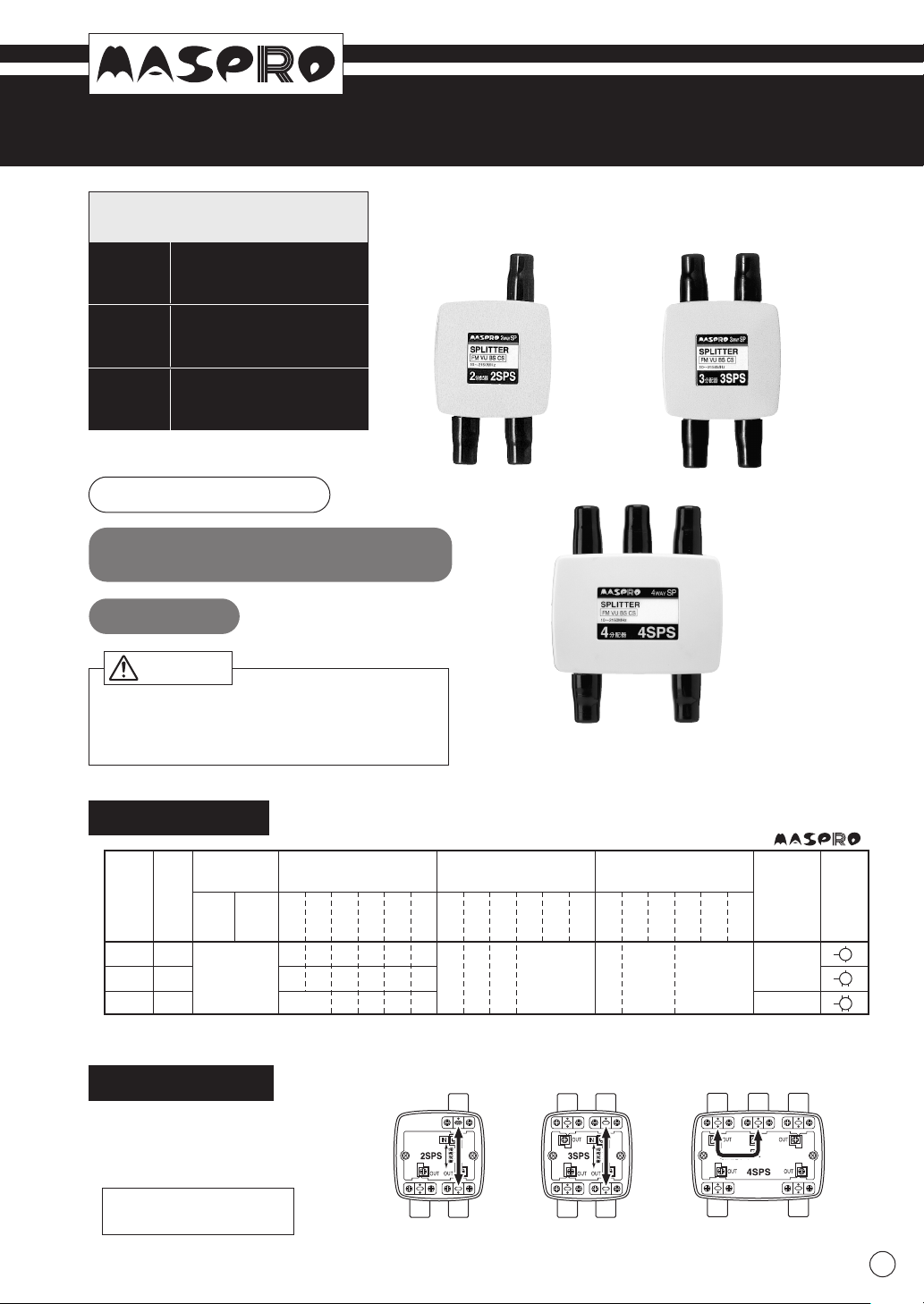
SPLITTERS for Home Use
Frequency Range
10 - 2150MHz
2SPS
INSTRUCTION MANUAL
Direct-connect port
Read this instruction manual carefully before use.
2-way
3SPS
3-way
4SPS
4-way
Specifications
MASter of PROduction
1
Type
2-way
3-way
4-way
Model
IN75OUT
Impedance
(
Ω
)
Max. Splitting Loss
(dB)
Min. Isolation Out-to-Out
(dB)
Dimensions
(mm)
HxWxD
76x60x26
76x85x26
Symbol
Max. Voltage
Standing Wave Ratio
10
76
MHz
76
222
MHz
222
770
MHz
770
1336
MHz
1336
1895
MHz
1895
2150
MHz
4.2
6.3
8
464.3
7
8.5
4.8
8
9.8
6
9
10711
10 13 20 18 15 2 1.8 2
2SPS
3SPS
4SPS
Power passing between IN and one specified OUT port.
Power passing capacity: 1A (at 30V AC / 15V DC)
You can always rely on MASPRO's performance data.
4-way Splitter
4SPS
2-way Splitter
2SPS
3-way Splitter
3SPS
Power passing between IN and
one specified OUT port
Output the TV signals divided equally.
-
-
-
-
-
-
10
76
MHz
76
222
MHz
222
770
MHz
770
1336
MHz
1336
1895
MHz
1895
2150
MHz
-
-
-
-
-
-
10
76
MHz
76
222
MHz
222
770
MHz
770
1336
MHz
1336
1895
MHz
1895
2150
MHz
-
-
-
-
-
-
Caution
When you hear thunder, don't touch any
lead-in cable from the TV antenna. It may
cause electrical shock.
Power Passing
Power passing possible between
arrow-marked IN and OUT ports,
shown in illustration right.
Power passing capacity:
1A (at 30V AC / 15V DC)
IN INOUT INOUT OUT
OUT OUTOUT OUT OUT OUT
2SPS 3SPS 4SPS
Indoor Use
Page 2
MASter of PROduction
2K56-474 KW
(
B
)
·17-5474-2C
Flathead screwdriver
Wooden wall
Lid-removing slot
Lid
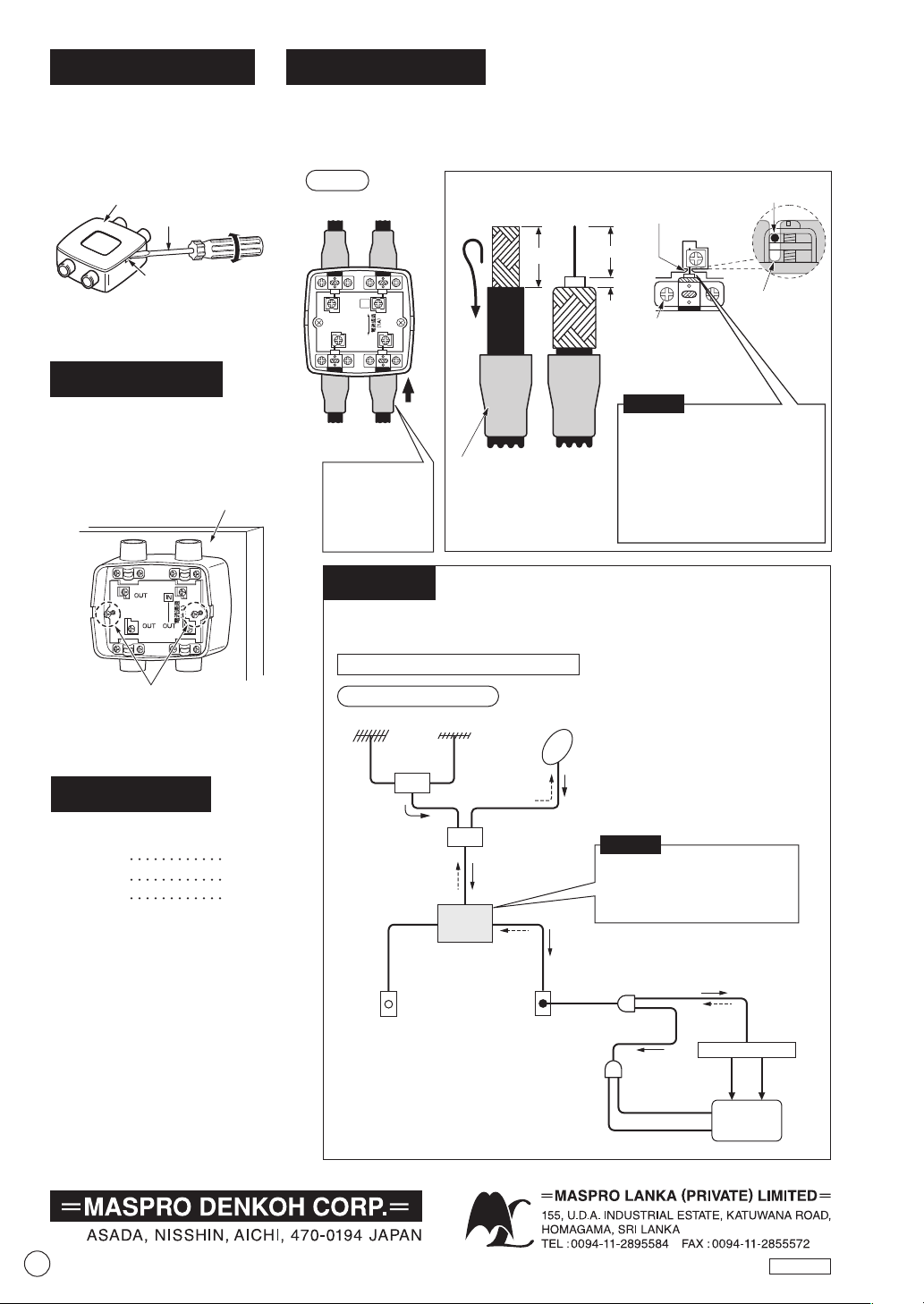
How to Open Lid
Insert a flathead screwdriver
into the lid-removing slot,
then twist the driver right
and left to remove the lid.
How to Connect
Example
2-port Distribution
3SPS
• Connect cable to corresponding ports, marked IN and OUT.
• After passing Dust protection boot over the cable, prepare the cable end
as shown below.
How to Install
Install the splitter on a flat
surface with the wood screws
attached to the case.
For satellite reception, use units and cables which meet the
performance requirements for the satellite frequency range.
From
Antenna
To TV
To TV To TV
Fold back
12mm
10
Loosen the screw, then
place the center conductor
along the plastic guide.
2
Dust protection boot
(accessories)
21
• Make sure the braided wires of
the coaxial cable DO NOT touch
the center conductor.
• When you use the foil-wrapped
coaxial cable, take care that the
foil DOES NOT touch the center
conductor itself and/or its
terminal.
Satellite Mixer
Satellite
Separator
Power
Insertion
Type
Satellite
UHF
VHF
Satellite
VHF, UHF, Satellite
VHF, UHF, Satellite
Satellite
VHF, UHF
VHF/UHF Mixer
15V DC
15V DC
15V DC
15V DC
2
Cable fixing
screw (3 pcs.)
• Tightening torque
0.7N
•
m
(7.2kgf
•
cm)
2-way
Splitter
2SPS
VHF, UHF
Wall outlet
VHF/UHF Separator
Audio Video
Wall outlet
VHF
UHF
Wood screws
3SPS
Caution
Push in the dust
protection boot
completely in the
direction of the
arrow.
3SPS
IN
OUT
OUTOUT
(cutting length is full scale)
Center
conductor
Guide
TV
Connect the cable coming from
the power-passing wall outlet to
the Splitter's power-passing
(arrow-marked) output port.
VHF,UHF, Satellite Reception
Satellite Receiver
()
JUL., 2011
Accessories
Dust Protection Boot
Specifications and external design
are subject to change for further
improvements.
2SPS 3pcs.
3SPS 4pcs.
4SPS 5pcs.
Caution
 Loading...