

Page 1
Instructions
Gas Fireplace with Masonry Firebox
Models MGFP39/44/49
Equipped with Safety Pilot System / Remote Control Valve
WARNING:
n
If the information in these instructions is
not followed exactly, a fi re or explosion
may result causing property damage,
personal injury or death.
Do not store or use gasoline or other
fl ammable vapors and liquids in the
vicinity of this or any other appliance.
WHAT TO DO IF YOU SMELL GAS:
Do not try to light any appliance.
•
Do not touch any electrical switch; do
•
not use any phone in your building.
Immediately call your gas supplier from
•
a neighbor’s phone and follow the gas
supplier’s instructions.
If you cannot reach your gas supplier,
•
call the fi re department.
Installation and service must be
performed by a qualifi ed installer, service
agency, or the gas supplier.
IMPORTANT: READ THESE INSTRUCTIONS
CAREFULLY BEFORE STARTING
INSTALLATION OF THIS FIREPLACE.
The logs and burner must be permanently installed in and
are only for use in this fi replace. This fi replace must be
connected to a working fl ue meeting the requirements of
the ANSI Z21.50 standard.
Solid-fuels shall not be burned in this fi replace.
This appliance must be vented vertically through the
roof. This appliance is not for installation in manufactured
or mobile homes. The installation, including provisions
for combustion, ventilation air, and required minimum
permanent vent opening, must conform with the National
Fuel Gas Code (ANSI Z223.1/NFPA 54) and applicable
local building codes. This gas fi replace is designed to
burn with yellow fl ames; thus adequate ventilation is
absolutely necessary.
WARNING:
n
This gas appliance must not be connected to a chimney
fuel servicing a solid fuel burning appliance.
Do not store gasoline or other fl ammable vapors and liquids in the vicinity of this or any other appliance.
Installer: Leave these instructions with the consumer.
Consumer: Retain for future reference.
This appliance is only for use with the type
of gas indicated on the rating plate. This
appliance is not convertible for use with
other gases, unless a certifi ed kit is used.
REV 10/23/2012
Report No. 08-154
ICC Evaluation Services
Report No. 2401
Page 2

THIS PAGE INTENTIONALLY LEFT BLANK
Page 3
CONTENTS
CONTENTS
Contents ..........................................................................................................................................Pg. 1
Fireplace Parts List .......................................................................................................................... Pg. 2, 3
Burner and Logs Parts List ..............................................................................................................Pg. 4
Product Overview ............................................................................................................................Pg. 5, 6
Clearance To Combustibles .............................................................................................................Pg. 7
Mason-Lite Fireplace & Chimney Systems ......................................................................................Pg. 7
Chimney System Heights ................................................................................................................Pg. 7
Supporting Floor Systems ...............................................................................................................Pg. 8, 9
What You Will Need .........................................................................................................................Pg. 10
Fireplace Assembly Procedures ......................................................................................................Pg. 11, 12
Mason-Lite Firebrick Liner ...............................................................................................................Pg. 13
Installing Outside Air ........................................................................................................................Pg. 14
Mason-Lite Chimney Systems ......................................................................................................... Pg. 14
Determining Finished Height for Fireplace ......................................................................................Pg. 14, 15
Installing Vent Plate and Chimney Systems .................................................................................... Pg. 15
Venting Installation ........................................................................................................................... Pg. 16
Specifying Chimney Heights ............................................................................................................Pg. 17
Chimney Termination Units ..............................................................................................................Pg. 17
Important Pre-installation Information ..............................................................................................Pg. 17
Installing the Valve/Control Box Assembly ....................................................................................... Pg. 18
Install Spill Switch and Baffl e Assembly .......................................................................................... Pg. 18
Owner’s Operation & Precautions ...................................................................................................Pg. 18, 19
Attaching the Burner and Grate ....................................................................................................... Pg. 19
Checking and Adjusting the Pilot ..................................................................................................... Pg. 19
Placing the Decorative Lava Rock ...................................................................................................Pg. 19
Adjusting Air Mixers .........................................................................................................................Pg. 19
Log Placement .................................................................................................................................Pg. 20
Lighting and Operating Instructions ................................................................................................. Pg. 21
Maintenance and Service ................................................................................................................Pg. 22
Troubleshooting ...............................................................................................................................Pg. 22
Appendix I ........................................................................................................................................Pg. 23
Appendix II .......................................................................................................................................Pg. 24
Warranty ..........................................................................................................................................Pg. 25
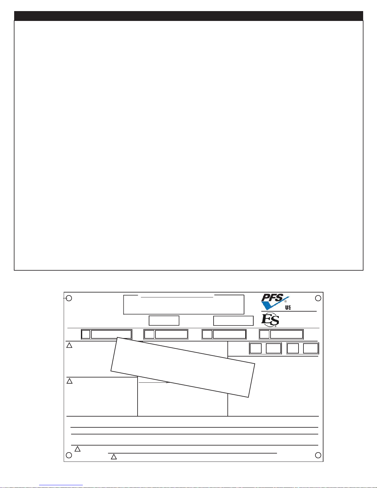
Below is a sample picture of the rating plate that is located inside the lower dome side of your fi replace. Model Number, Date Of Manufacture
and Serial Number should be stamped on the plate where indicated.
DO NOT REMOVE THIS LABEL
Masonry
Fireplace
MFI
315 WEST 3RD ST.
SANTA ANA, CA 92701
MODEL
No.:
!
WARNING:
THIS FIREPLACE HAS BEEN TESTED
FOR USE ONLY WITH APPROVED
GLASS DOORS. TO REDUCE THE
RISK OF FIRE OR INJURY, CONSULT
OWNER’S MANUAL.
!
THIS FIREPLACE IS DESIGNED
FOR USE ONLY WITH THE ANSI
Z21.50 DECORATIVE GAS LOGS
AND BURNER TESTED AND
APPROVED FOR THIS FIREPLACE.
Consult instructions included with this
firebox for further information.
This appliance is not for installation in manufactured or mobile homes.
The installation, including provisions for combustion, ventilation air, and required minimum permanent vent opening,
must conform with the National Fuel Gas Code (ANSI Z223.1/NFPA 54) and applicable local building codes.
!
WARNING: This gas appliance must not be connected to a chimney fuel servicing a solid fuel burning appliance.
rev 18 NOV 2009
Industries, LLC
MGFPST-43
THIS APPLIANCE NEEDS FRESH AIR FOR SAFE OPERATION AND MUST BE INSTALLED
SO THERE ARE PROVISIONS FOR ADEQUATE COMBUSTION AND VENTILATION AIR.
See MFI’s installation and operating instructions for this
model. Contact local building officials about restrictions
and installation specifications in your area.
DATE OF MFG.
SERIAL No.
MGFP-39 MGFP-44 MGFP-49
!
WARNING:
Use only approved, listed chimneys
MGFP-39/44/49:
10” B-Type Vent and DM-12-10” system
EXAMPLE ONLY
MGFPST-43:
12” B-Type Vent and DM-12-12” system, UL 103
chimney or a 12” class A chimney if preferred.
Chimney Heights:
Max.: 40 ft.
Min.: 14 ft. (17 ft. with 1 or 2 offset
sections maximum)
IMPORTANT: Refer to pipe
manufacturer’s instructions.
!
WARNING:
THIS FIREPLACE IS NOT INTENDED FOR BURNING SOLID FUELS.
Tested &
Listed By
GAS
TYPE:
FIREPLACE CLEARANCES TO COMBUSTIBLES:
UNIT FRONT, SIDES, REAR...............................0” (0 mm)
COMBUSTIBLE FLOOR......................................0” (0 mm)
COMB. SHEATHING ABOVE OPENING TOP.....8” (200 mm)
SHEATHING OR TRIM TO OPENING SIDES....12“ (300 mm)
OPENING TO SIDE WALL..................................20” (500 mm)
HEARTH EXTENSION BEYOND SIDES............12“ (300 mm)
INSULATION FROM FIREBOX............................0” (0 mm)
FOR MANTEL CLEARANCES
CONSULT OWNER’S MANUAL
NG LP
Report No.
08-154
ICC Evaluation
Services Report
No. 2401
1
Page 4
Fireplace Parts List
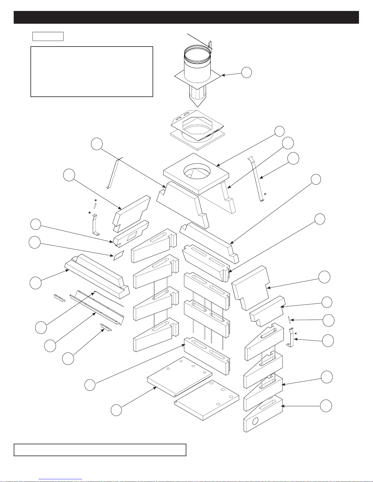
Figure 1
WARNING
Failure to position the parts in
accordance with these diagrams or
failure to use only parts specifi cally
approved with this appliance may result
in property damage or personal injury.
Fireplace Parts List
12
9
11
10
8
7
6
10
17
5
4
8
7
16
14
15
2
1
See Page 8 and 9 for framing anchoring components.
18
19
3
3A
2
Page 5
MGFP39/44/49 Fireplace Parts List
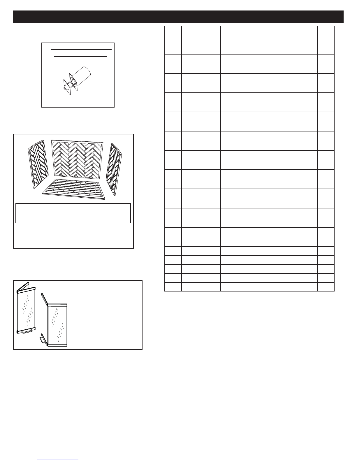
MGFP39/44/49 Fireplace Parts List
Optional Outside Ø4”
Combustion Air Kit
Model No.: MFP4-AK
(Ø4” Ducting not included)
MFP(39,44,49)SHBL- Herringbone
MFP(39,44,49)FRBL- Running Bond
Refractory Firebrick Liners
(Herringbone Pattern shown, also available
in Running Bond - see Pg.27)
ITEM P/N DESCRIPTION
MFP39-1
1
2
3
3A
4
5
6
7
8
9
10
11
12
14
15
16
MFP44-1
MFP49-1
MFP39-2
MFP44-2
MFP49-2
MFP39-3
MFP44-3
MFP49-3
MFP39-3A
MFP44-3A
MFP49-3A
MFP39-4
MFP44-4
MFP49-4
MFP39-5
MFP44-5
MFP49-5
MFP39-6
MFP44-6
MFP49-6
MFP39-7
MFP44-7
MFP49-7
MFP39-8
MFP44-8
MFP49-8
MFP39-9
MFP44-9
MFP49-9
MFP39-10
MFP44-10
MFP49-10
MFP186-1
MFP-DD*
MFP-211
MFP-212
MFP-213
HEARTH (Left or Right)
REAR WALL
SIDE WALL
SIDE WALL with 4” opening for Air Kit
SMOKE SHELF (Downdraft Diverter)
DOME REAR - LOWER
LINTEL
DOME SIDE - LOWER
DOME SIDE - UPPER
DOME TOP Ø10”
DOME FRONT/REAR
RATING PLATE
10” DRAFT HOOD
SMOKE DIVERTER
SMOKE DIVERTER EDGE PIECE
SPILL SENSOR SWITCH
QTY
2
3
7
1
1
1
1
2
2
1
2
1
1
1
2
1
Only the following
doors have been tested
and approved for use
with this fireplace:
Crown-Breckinridge
or
McKenzie-Pendelton
* ITEMS NOTED ARE SOLD SEPARATELY.
ITEMS INDICATED AS “NOT SUPPLIED” CAN BE
OBTAINED FROM YOUR LOCAL HARDWARE STORE.
3
Page 6
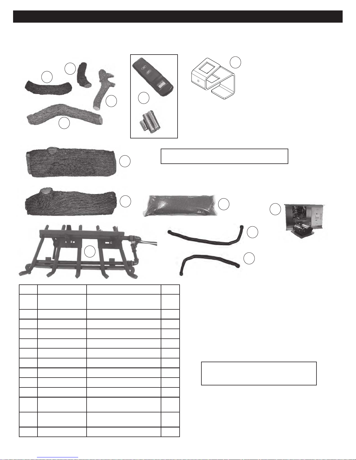
Burner & Logs Parts List
Burner & Logs Parts List
Before beginning installation, be sure the burner system is complete by comparing its contents with this Parts List. Parts may
differ depending upon the size of the set purchased. Be sure you know the model number and size of your set when ordering
replacement or optional parts and accessories.
7
9
10
LML-24 shown.
13
8
11
12
2
Diagrams shown are not to scale.
6
5
1
ITEM P/N DESCRIPTION
GMLB-39/44-01(P)
1
GMLB-49-01(P)
RR-1A
2
CK-5-18HC Source connector kit
3
CK-5-24HC Burner connector kit
4
CE-01 Valve/Control box w/ batt.
5
OCC-10 Lava Rock, 10 lb. bag (4)
6
LML-15T Top log 15”
7
LML-17T Top log 17”
8
LML-18T Top log 18”
9
LML-20T Top log 20”
10
LML-24BR
11
LML-30BR
LML-24BF
12
LML-30BF
MFP-214 Burner Grate Brackets (2)
13
Pilot, Burner assembly
Remote trans./recvr. w/ batt.
Rear bottom log 24”
Rear bottom log 30”
Front bottom log 24”
Front bottom log 30”
QTY
1
1
1
1
1
1
1
1
1
1
1
1
2
3
Receiver pre-assembled
4
into control box.
Contact MFI for replacement parts and
accessories as listed in these parts lists.
4
Page 7
Product Overview
Introduction
We extend a warm welcome from all of us at Masonry
Fireplace Industries, LLC. (MFI), proud manufacturers of
Mason-Lite Fireplaces. Thank you for Choosing MFI.
You may have thought long and hard before you chose the
fi replace which would grace your home. Rest assured that
every component of the Fireplace has been tested to ensure
long-term durability.
Product Overview
Mason-Lite Fireplaces are designed as factory-built blocks
to be assembled on-site. These fi replaces may be installed on
either combustible or non-combustible fl oors. In order to func-
tion, the system requires a 10” B-vent chimney.
The main components of the Mason-Lite Fireplace are:
Mason-Lite Firebox and Smoke Dome
●
Gas burner, logs and control system
●
B-vent
●
Careful step-by-step instructions for each phase of the installation procedure will be given for the Mason-Lite fi replace.
Those instructions generally fall into the following categories:
Spacing and clearance as it relates to combustible materials
●
Familiarity of installation for all components
●
The strength of the fl oor on which it rests
●
Chimney system measurements
●
Set up and use of the gas burner system.
●
Choice of materials and craftsmanship in fi replace and hearth
●
fi nishing.
Figure 4 - Typical Installations
WARNING! Under no circumstances should you allow children
to remain unattended while a fi re is burning in the fi replace! Be
sure to keep all objects – furniture, drapes, rugs, etc. at least
48” (48 inches) away from the opening of the fi replace!
Attention: You may need a residential building permit to install
a Mason-Lite Fireplace. Consult local jurisdictions before you
get started!
The MASON-LITE gas fi replace is not designed to serve as a
primary heat source, rather, the fi replace was expressly created
as a supplemental source of heat. This unit is designed for use
with the provided gas burner and approved logs only.
Testing and listing for the MASON-LITE gas fi replace has been
undertaken by PFS Test Laboratories, Inc. to ANSI Z21.50.
Under no circumstances should the MASON-LITE gas
fi replace be considered for other than in-residence buildings of
conventional construction.
These components make up the MASON-LITE gas fi replace
and in the following pages, you will learn how they work
together to create an exceptional unit that will give years of
service and pleasure!
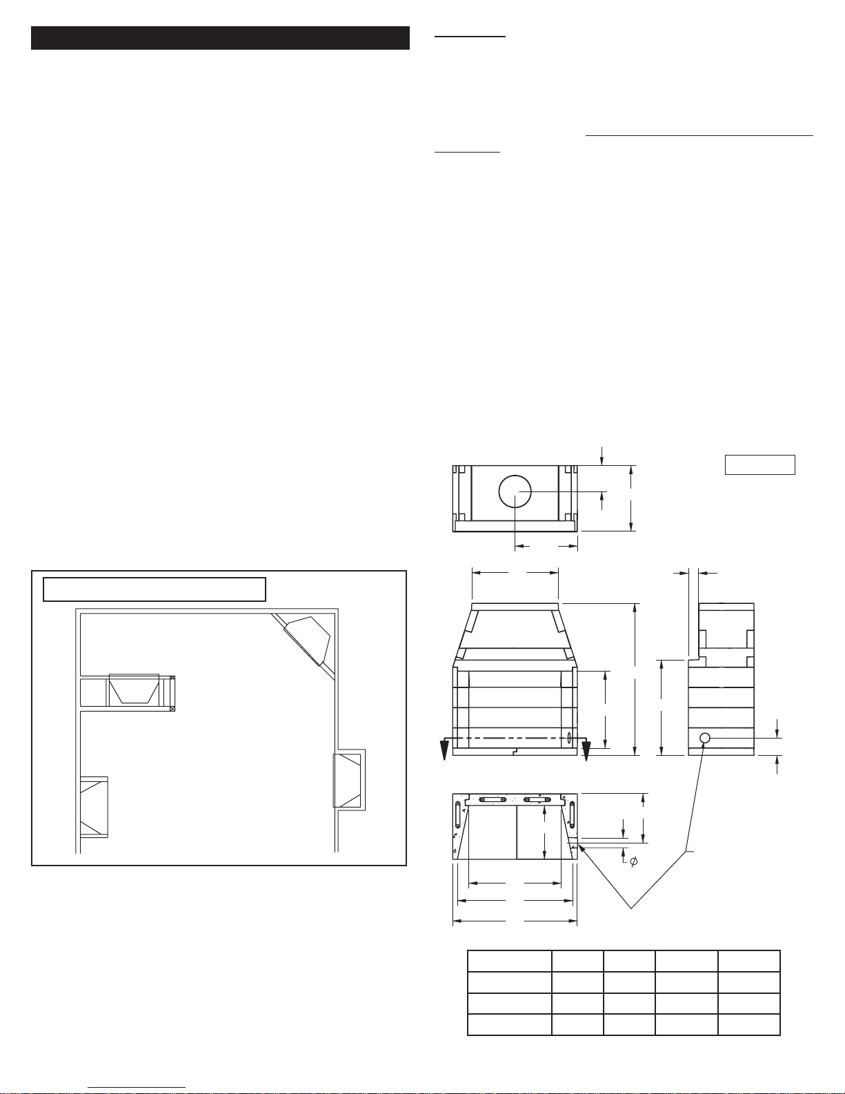
Figure 5
11"
28"
A/2
D
4 3/8"
Internal
Wall
Installation
Corner
Installation
Flush
Full
Installation
Projection
Installation
Note that each of these topics will be covered in detail and that
the installer is expected to understand each phase completely
before going on to subsequent instructions.
Attention: Be advised that all the illustrations in this manual
are for general reference only. Do not scale drawings. Actual
design elements will vary from case to case. Pay attention to
specifi ed minimum clearances to combustibles.
63-1/2”
32 7/8"
23"
C
B
A
40 5/8"
21"
4 1/4"
ø4” OUTSIDE AIR
ACCESS - CAN
BE INSTALLED
ON THE LEFT
SIDE ALSO
Overall Dimensions MASON-LITE Fireplaces
Model A B C D
MGFP39 43” 39” 30-1/4” 27-3/4”
MGFP44 48” 44” 35-1/4” 32-3/4”
MGFP49 53” 49” 40-1/4” 37-3/4”
7 3/8"
5
Page 8

Required Gas Pressure
The minimum inlet gas supply pressure for the purpose of
input adjustment is 5” of water column (w.c.) for natural gas.
The maximum inlet gas supply pressure is 10.5” w.c. for
natural gas. The minimum inlet gas supply pressure for the
purpose of input adjustment is 11” of water column (w.c.) for
propane gas. The maximum inlet gas supply pressure is 13”
w.c. for propane gas.
Testing the Gas Supply System
The gas fi replace and its required individual shut-off valve
must be disconnected from the gas supply piping system
while performing any tests of the piping system at pressures in
excess of 1/2 psig.
The gas fi replace must be isolated from the gas supply
piping system by closing its individual manual shut-off valve
during any pressure testing of the gas supply piping system at
test pressures equal to or less than 1/2 psig.
This is accomplished by closing the gas supply line valve
required by NFPA 54.
A fi replace screen must be replaced after service and be
in place when the appliance is in operation and, unless other
provisions are provided, the screen shall have an opening for
introduction of combustion air.
When glass fi replace doors are used, operate the gas
fi replace with the doors open. Use only doors rated for this
appliance.
Important
To comply with building code acceptances, and for safe
operation and proper performance of this fi replace, use ONLY
MASON-LITE parts and accessories.
Use of other controls, parts, and accessories which are not
designed for use with MASON-LITE gas fi replaces is prohibited
and will void all warranties, certifi cations, listings, and building
code approvals, and may cause property damage, personal
injury, or loss of life.
The burner included with this gas fi replace is non-convertible
and only meant to be used with the gas listed on the rating
plate.
GUIDELINES FOR USE:
All current and future users of Mason-Lite Fireplaces
are charged with the responsibility for full knowledge of the
information contained within this manual which includes:
Strict requirements for assembly.
•
Detailed instructions for installation.
•
Cautionary guidelines for use.
•
On-going maintenance instructions.
•
It is the responsibility of the distributor, subcontractor and/
or the general contractor – whoever shoulders the liability
for installation of this product – to see to it that the work is
in complete compliance with the guidelines and instructions in
this manual.
Note that the general contractor is the party accountable for
seeing that adequate clearances are provided from all fi rebox
surfaces per specifi cations in this manual.
DO NOT USE A FIREPLACE INSERT OR OTHER PRODUCTS
NOT SPECIFIED FOR USE WITH THIS FIREPLACE.
The Mason-Lite is Designed for Use Only with:
- The supplied burner and log system
- Plumbed LPG or Natural Gas.
DO NOT USE OR STORE GASOLINE OR OTHER
FLAMMABLE LIQUIDS OR GASES IN OR NEAR THE
FIREPLACE!
ATTENTION: A fi re or an explosion could occur causing
property damage, injury or loss of life if you do not follow the
information in this manual!
6
Page 9

Clearance to Combustibles
Clearance to Combustibles
Mason-Lite Fireplace & Chimney Systems
The distance to be maintained from the surfaces of the
fi replace to combustibles must be observed. Below is a list of
the most common combustible materials to name a few:
Drywall Wood fl ooring Plywood
Sub-fl ooring Wood Framing Particle board
Mill board Plywood paneling
Maintain the following minimum clearances:
Unit front, sides, rear 0” (0 mm)
Combustible fl oor 0” (0 mm)
Sheathing or trim to opening sides
Combustible sheathing above opening top
Mantel above opening
8”
(203 mm)
8”
(203 mm)
12” (305 mm)
Mason-Lite Fireplace & Chimney Systems
Before Getting Started…
Even if you consider yourself an expert in the fi eld of
fi replace installation, we at Masonry Fireplace Industries
caution you to take the time to totally familiarize yourself with
the instructions to follow.
We can assure you that there will be information that will
make the installation go smoother and, above all, safer, for
everyone concerned. At the least, reading these procedures will
save you time and, at the most, it will prevent any malfunction
that could result in property damage or serious injury.
Do not start the installation until you have checked out all
the local, regional, state and national rulings, laws and codes
as they apply to fi replaces and fi replace installations. Every
community is different so do not assume that because you
know the requirements for one locality, it will be the same in
the next. Avoid bureaucratic hassles and do your homework
WELL BEFORE you start your project!
Opening to side wall
Insulation from fi rebox
Due to high temperatures, never install this fi replace in a
recreational vehicle, in high traffi c areas, drafty areas, or
where curtains, furniture, clothing, or other fl ammable objects
are less than 36” from the front or side and 42” from the top of
the fi replace.
CAUTION: This gas fi replace attains high temperatures. Keep
children and adults away from hot surfaces to avoid ignition of
clothing and/or burns. Even after the fi replace is shutdown it
will remain hot for a time afterward. Allow the surface to cool
before touching it.
Carefully supervise young children when they are in the room
with the fi replace.
All fi replace openings for both combustion air and exhaust
must remain open and unobstructed at all times when the
fi replace is in operation.
The MASON-LITE fi replace has been designed, tested
and approved for zero clearance to combustible fl oors.
Be certain that the MASON-LITE fi replace is installed with
the fi nished fi re brick fl oor of the fi replace so that it is at least
4-1/2” (four and a half inches) above the combustible fl oor
system.
Warning to the structural engineer and/or building contractor:
It is your responsibility to be certain that the fi replace can be
properly supported by the combustible fl oor system on which
the fi replace will rest. Be advised that this engineering equation
will be in addition to any live or dead weights that the fl oor has
to carry.
20” (508 mm)
0” (0 mm)
The MASON-LITE gas fi replace is designed to be
1)
installed with a B-vent metal chimney system, UL 103
chimney. Such chimney systems are acceptable where
any traditional masonry fi replace has been specifi ed.
Note that the chimney system must always vent to the
outside of the building.
This Mason-Lite fi replace is intended as a supplemental heat
2)
source only. It is not intended as a primary heat source.
It is the responsibility of the contractor installer (not the
3)
manufacturer) to ensure that adequate combustion air is
provided for proper function of this fi replace. Fireplaces
take up a large volume of replacement air from outside the
house and if the house is of airtight construction, smoke
spillage may occur if proper draft is not achieved.
There are many conditions beyond a manufacturer’s
4)
control when it comes to the operation of the fi replace.
The manufacturer cannot be responsible for “smoke free”
operation, nor can the manufacturer take on the responsibility
for problems with surrounding construction; chimneys that
have not been built at the right heights; system drafts caused
by faulty mechanical systems; adverse weather conditions
or any other inclement environmental situations over which
the manufacturer has no control.
Inspect all fi replace & chimney components for evidence
5)
of damage prior to starting installation. Consult your local
distributor for replacement parts if necessary.
Under no circumstances should you make any adjustments
6)
or modifi cations to the chimney system during the
installation procedure. If you do, you are not only liable
for negating the warranty, but you could very well cause a
serious malfunction of the fi replace. You must follow these
chimney instructions.
Chimney System Heights
When installed, the maximum overall height of the Fireplace is
40’-0” (forty feet). The minimum installed height of the
completed fi replace is 14’ 0” (fourteen feet), given that the
chimney is straight. If the chimney includes one or more offset
sections, the measurement is 17’ 0” (seventeen feet).
7
Page 10
Supporting Floor Systems
It is the ultimate responsibility of the installer to ensure that
proper concrete slab supports are used.
WARNING to the licensed design professional and/or building
contractor: It is your responsibility to be certain that the MasonLite can be properly supported by the combustible fl oor system
on which the fi replace will rest.
For fi replace support foundations installed on concrete refer to
Appendix I and II (pages 31 & 32) for specifi c instructions.
Rebar locations
Lay-out the position of the fi replace and drill holes where
the rebar will be located. Secure the #3 rebar 4 inches into
the concrete foundation with ITW Epoxy or Simpson Epoxy.
Follow manufacturer’s instructions for installation of rebar into
slab.
Wood Floor
Anchorage of fi replace to wood fl oor construction is required.
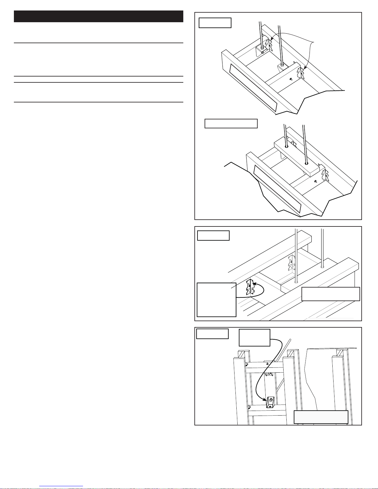
Refer to Figure 9 for anchorage dimensions. Four anchors are
required to attach to the sub-fl ooring framing.
Crawl Space or Upper Floor:
For installation of fi rebox over combustible crawl spaces or
upper fl oors, anchorage of the fi rebox is required. Illustrations
of examples of possible anchorage methods are shown in
Figures 6 thru 8 depending upon the type of fl oor framing. Final
method of anchorage is to be determined by licensed design
professional.
For conventional framing, where the fl oor joists are parallel
with the sides of the fi rebox, the addition of fl oor joists to align
with the anchor brackets allows the brackets to be directly
connected to the fl oor joists.
Figure 6
Metal Base
Assembly
EXAMPLE ONLY
Floor Sheathing
not shown for
clarity
Figure 7
I-Joist Anchoring
Top View
A35 Brackets
(16 required)
2X FLOOR JOIST
2X FLOOR JOIST
Note that additional fl oor joists may be required to support
the weight of the fi rebox and chimney. Where the fl oor joists
run parallel to the front of the fi rebox, anchorage can be
accomplished in like manner as shown in Figure 6 using
blocking between the fl oor joist.
For fl oors supported by I-Joists, the method of anchorage is
illustrated in Figures 7 and 8. Figure 11 illustrates the general
arrangement of anchorage to fl oor framing.
It is important to take into consideration that the load for
the Mason-Lite Fireplace must be considered as additional
dead load that will have to be supported by the fl oor framing.
Additional fl oor joists or I-joists may be required as determined
by the licensed design professional.
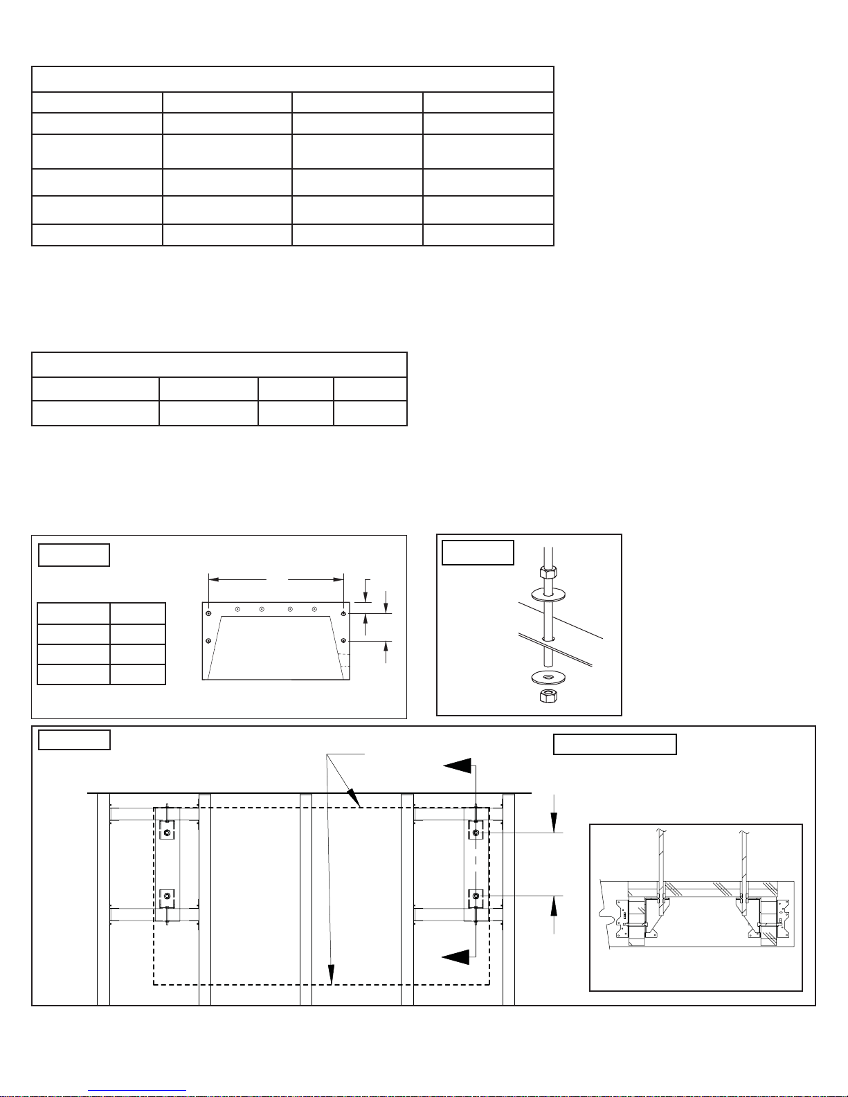
The dead weights for the fi replace are noted in Table I. It is
the task and responsibility of the general contractor/installer
to see that the proper reinforcement for weight loads are
made by a licensed design professional prior to the fi replace
installation.
As stated above, it is desirable to place additional framing
for alignment of anchor rods. Refer to Figure 9 for anchor rod
locations.
Simpson
Strong-Tie
A-35 or
equivalent
Figure 8
I-Joist
Anchoring
Bottom
View
Example Only
ist
I-Jo
Anchor
Brackets
I-JOISTS
Example Only
8
Page 11
MASON-LITE Weight Determination
The following are dead load weight estimates for the Mason-Lite Fireplace.
Table I
Fireplace Model
Fireplace Weight
Mortar, Rebar &
Ready Mix Concrete
Firebrick Lining
MGFP39 MGFP44 MGFP49
1,194 lbs. 1,250 lbs. 1,359 lbs.
350 lbs. 357 lbs. 364 lbs.
333 lbs. 345 lbs. 356 lbs.
Draft Hood
Floor Area
Other Weight Considerations:
Fireplace fi nished facing (surround): This information needs to be obtained from the contractor.
1)
Weight of metal fl ue: See chimney manufacturer’s weight specifi cations. Some chimney systems can weigh up to 50 lbs per
2)
lineal foot.
17 lbs. 17 lbs. 17 lbs.
42” x 28” (8.12 ft²) 48” x 28” (9.33 ft²) 53” x 28” (10.30 ft²)
Table II - Defl ection Limits
Construction L S or W D +L
Floor Members
1
For wood structural members having a moisture content of less than 16 per cent at time of installation and used under dry
conditions, the defl ection resulting from L + 0.5D is permitted to be substituted for the de fl ection resulting from L + D.
Note that MASON-LITE cannot accept responsibility for structural fl oor support details. All drawings are presented as mere
illustrations to indicate the presence of the underlying fl oor system. It is the responsibility of the general contractor/installer to
consult with a local licensed design professional for guidance in building a proper fl oor support system.
Figure 9
I/360 --- I/240
F
A
1
Figure 10
4"
Model A
MGFP39 38-3/4”
MGFP44 43-3/4”
MGFP49 48-3/4”
Figure 11
T ypical Anchorage
Layout
10"
Fireplace
outline
EXAMPLE ONLY
10”
SECTION VIEW
ROTATED 90CW
9
Page 12

ATTENTION: Figure that these totals for the dead loads are
in addition to the actual live load as well as other dead load
requirements for the specifi ed site’s proposed fl oor. Only the
MASON-LITE weights are known. Other weights are estimates
and are subject to material choices of the installer or owner.
What You Will Need
You will fi nd that the MASON-LITE Fireplace is designed to be
completely assembled on-site, consisting of interlocking precast
parts. The parts of the fi replace are made of Mason-Lite’s
incredibly strong blend of specialty cement and a light weight
aggregate.
IMPORTANT! When applying mortar, it is imperative that the
concrete blocks be maintained moist (not soaking) so they don’t
absorb the water out of the mortar and cause adhesion to fail.
Frequently run a damp sponge to the parts before mortar is
applied!
The installation of an anchor plate/damper is required but not
supplied. You may purchase it from any chimney manufacturer
or MFI. Also, an optional combustion air inlet MFP4-AK can be
obtained from MFI.
Refractory Firebrick Liners also need to be installed. These
should be a minimum of 1-1/8” (one and one-eight inches) thick.
The liner will be applied within the walls and hearth area of the
fi rebox. These are available from MFI. See page 27.
Tools needed for installations:
One 4’ level
●
Roto-hammer with ½” drill bit (needed for concrete slab
●
install only)
Drill motor with mixer blade (to mix Mason-Lite Mortar)
●
Two empty 5 gallon buckets (to mix Mason-Lite Mortar)
●
One wheelbarrow and shovel to mix concrete.
●
Grout bag
●
Triangular masonry trowel
●
Rubber hammer
●
Sponge and water bucket to wipe down and moisten parts
●
prior to applying mortar.
Materials needed for concrete slab installations
MGFP39:
Six (6) pieces 3/8” rebar x 36” long (included with unit)
Six (6) pieces of rebar x 12” long (included with unit)
MGFP44/49:
Eight (8) pieces 3/8” rebar x 36” long (included with unit)
Eight (8) pieces of rebar x 12” long (included with unit)
Eight (8) pieces 3/8” rebar x 36” long (included with unit)
Eight (8) ea. All-thread x 12” long (with nuts and washers)
ALL UNITS:
Three (3) - 90 lb. bags of ready mix concrete with 1/4” or smaller
aggregate.
SURFACE CRACKS - The MASON-LITE FIRE-PLACES are
manufactured using high quality materials. During the
drying process, surface cracking may occur. These small
cracks (under 1/16” will not affect the fi replace safety or
performance). During the assembly process, fi ll surface
cracks with thin-set mortar and brush when drying for a
smooth surface fi nish.
Field Assembly Procedures
Mixing the MASON-LITE mortar – The mortar comes
a)
premixed and should be dry. Be sure to use clean water and
work it up into a mixture that is pasty but not lumpy. If it’s too
thin and the surfaces don’t stay moist, the components will
not adhere. Load the mixture into a standard grout bag.
Apply about ½” (one-half inch) thread of mortar. The mortar
b)
bead should be approximately ½” (one-half inch) away from
all edges. The mortar has a considerable amount of holding
power so do not overload the components with too much
mortar. Keep the components moist at all times!
Some mortar will “ooze out” when placing components
c)
together, this is normal. Wipe excess away with a trowel. Do
not cover component surfaces completely with mortar. Do
not apply the mortar in thick bands even if the component
you are working with is larger than the rest. You will want to
apply “stripes” of mortar in these situations.
Make sure components are level. It’s extremely important
d)
that you pay careful attention to how you are assembling
the Mason-Lite Fireplace since every component builds on
the next. If you have to make any kind of an adjustment,
do not try to do it “by loading an opening” with mortar, this
will only result in a fi replace that will not be plumb or level.
Use wood shims instead. You will fi nd these small wood
shims supplied with the Mason-Lite Fireplace and
you can nudge them in between openings to achieve the
precision you need in making component adjustments.
Once you have removed any shims, you will want to cover
any gaps that may have resulted with the mortar.
ALL UNITS:
Epoxy for securing rebar in footing / foundation.
●
Three (3) - 90 lb. bags of Ready-Mix Concrete with 1/4” or
●
smaller aggregate.
Materials needed for wood floor installations
MGFP39:
Six (6) pieces 3/8” rebar x 36” long (included with unit)
Six (6) ea. All-thread x 12” long (with nuts and washers)
MGFP-44/49:
10
Page 13
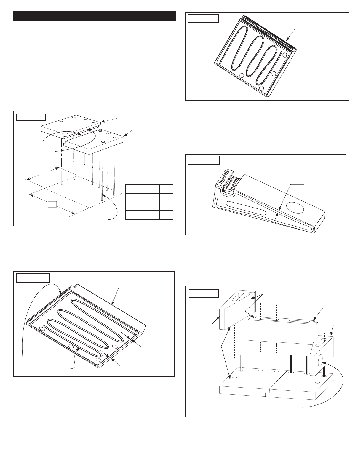
Fireplace Assembly Procedures
Fireplace Assembly Procedures
Place the Mason-Lite fi replace hearth on the fl oor where the
1.
fi replace is to be installed. For concrete slabs, supporting
fl oor needs to be rated at ASTM 90.
Draw an outline of the hearth area based on the dimensions
2.
shown in Figure 12. Position Hearth slabs and mark rebar
center locations. Drill 4 inches into concrete slab and secure
the 8 pieces of 12 inch rebar with epoxy. For other than
concrete slabs, draw an outline of the hearth area based on
the dimensions in Figure 5 taking special consideration on
the position of where the all-thread studs will be located in
relation to the anchoring locations. All-thread rods should
stick up through the holes on the hearth slabs.
Figure 12
Left Side Hearth 2nd
Right Side Hearth 1st
Apply mortar
between joints
28”
Figure 14
Before installing side walls, confi rm placement of outside
6.
Hearth shown prepared
for Left Side position
combustion air access (if required), this can be installed
either side depending on which side is accessible to outside
combustion air (all diagrams in this manual show the
combustion air inlet hole on the right side). Prepare side
wall and rear wall mating surfaces with the prepared mortar
and begin assembly.
Figure 15
Side Wall shown prepared for Right
Side Air Access.
For Left Side, bead opposite side.
Model W
MGFP-39 43”
W
12 inch rebar
MGFP-44 48”
MGFP-49 53”
Mix a batch of mortar and prepare Right Side Hearth bottom
3.
surface to be bonded as shown in Figure 13.
Align Right Side Hearth to the outline created. The overall
4.
width should allow for an approximate gap of 1/8” between
slabs for the additional mortar to unite the remaining slab.
Check for surface fl atness, level if necessary.
Figure 13
Apply mortar bead to
all mating surfaces.
Hearth section shown prepared
for Right Side position
1/2” mortar
bead (typical)
1/2” away
from edges
1/2” AWAY
FROM EDGES
Keep the assembly of the next sections of the fi rebox side
7.
walls moving up, keeping components moist, mixing mortar
as you need it and threading the mortar appropriately as
you stack each section, one onto the next. Constantly check
for squareness and levelness while building each course of
block. As you complete each section, make certain that you
adhere the mortar at each and every joint.
Figure 16
Side Wall
Apply
mortar
Apply mortar
Rear Wall
Side Wall
Apply mortar to the remaining Hearth except this time
5.
apply beading on surface to be facing fl oor as shown in
Figure 14.
Combustion Air Access
Right or Left (Right shown).
11
Page 14
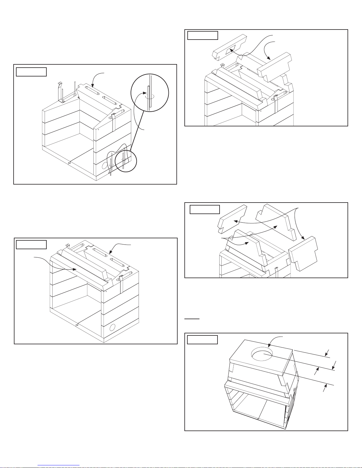
8.
Install Downdraft Diverter and fi nal row of Side Walls
(Figure 17). Then place #3 rebar (8 each, 36 inch long)
vertically through the cells until they reach bottom. Position
them adjacent to the rebar or all-thread sticking up from the
hearth.
9.
All components must be level. Mix approx. 2 cu. ft. of ReadyMix Concrete. Fill all cells with Ready-Mix Concrete mix.
Assemble Lower Dome Sides as shown in Figure 20. The
11.
beveled face lines up with the inward angles of the lintel
sides. Resulting top surfaces should be level.
Figure 20
Lower Dome Sides (Rating
Plate faces inside)
Figure 17
Downdraft
Diverter
12 inch
rebar or
all-thread
Set the Lintel and Lower Rear Dome as shown in Figure
10.
19. Check that all is level. If adjustments are needed, use
shims and fi ll gaps with an appropriate amount of mortar.
Note: Although you are cautioned to use MASON-LITE
mortar sparingly because it does have such holding power,
you should look over the fi rebox assembly at the end and fi ll
in any gaps, especially joint connections, with the mortar.
Figure 19
Lintel
Lower Rear
Dome
Verify that the smoke dome side, front and rear walls are
12.
aligning correctly and that the surfaces are smooth and
uniform. Make sure connections are covered with an
adequate amount of mortar. Remember that you have the
option of using shims but they must be removed and any
holes fi lled. Make any adjustments to the fi replace alignment
before continuing to the next step.
Assemble Upper Dome and Dome Sides as shown in
13.
Figure 21. Check your assembly here. If things are
proceeding as they should be, the fi nished top surface
should be fl at and level.
Figure 21
Upper Dome
Front/Rear
Upper Dome Sides
Important: Adjustments can only be made while the mortar
is still wet when correcting for squareness and leveling.
Finally, set the Dome Top into position. Be sure that it is
14.
fl ush in every direction as you place it on the crest of the
smoke dome wall assembly. After this is done, proceed to
section on “Installing Damper and Chimney System”.
Note: The chimney hole on the Dome Top is not centered from
front to back - it should be offset closest to the rear of the
fi replace (see Figure 22).
Figure 22
Center of chimney hole is
offset towards the rear.
10”
12-1/2”
MGFP-39/44/49
12
Page 15
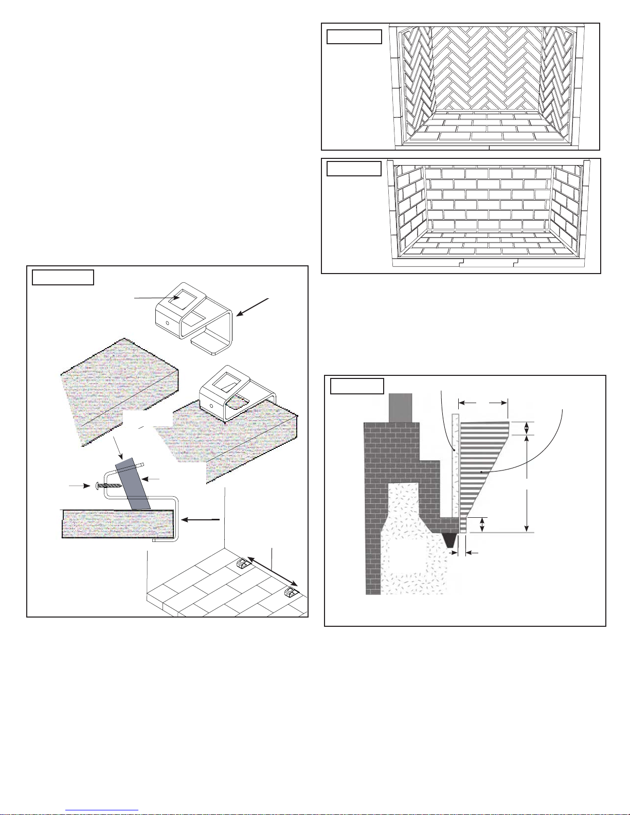
Mason-Lite Firebrick Liner
The fi rebrick lining is not supplied as part of your Mason-Lite
fi replace but can be purchased from MFI. They are available in
split herringbone and full running bond patterns. (see Figures
24 and 25)
You also have the option to have custom fi rebrick installed,
but it must be at least 1-1/8” thick.
Before you install the lining, you will need to drill all the
required gas and electrical line feeds and the combustion air
supply access holes.
Disclaimer: Masonry Fireplaces Industries cannot be held
liable for the way fi rebrick or fi rebrick mortar performs. It is
not unusual for heat stress cracks to appear on the fi rebrick or
fi rebrick mortar during the life of the fi replace.
Insertion of Leg Bracket
Insert metal grate leg lock bracket underneath the rear bricks as
shown and cement in place.
Figure 23
Insert leg here
Firebrick
Bracket
Figure 24
Figure 25
Fireplace Finishes & Combustible Trim Clearances
Mantel and Mantel Shelf Clearances – As with any radiant
1.
heat fi replaces, all Mason-Lite Fireplaces must comply with
building code safety clearances, per units that have
openings of 6 sq. ft. (six square feet) or greater. You must
keep combustibles such as trim 8” away from the fi rebox
opening (for mantel clearances, see Figure 26).
Figure 26
Combustible material
8”
Shelf or trim
safe zone
1”
One-way
screw
Cement in place
Burner
leg
Width of back
grate legs (cen-
ter)
12”
3”
Upper
fi replace
area
1.5”
Distances to underside
of shelf or trim
Mantel and side clearances
Attention: The manufacturer suggests that when building
out a fi replace, that the owner and installer opt for complete
safety. MFI, therefore, advises that combustible mantel
shelves feature clearances that are more than the 12”
(twelve inch) minimum equal to the projection of the shelf.
As a guide, fi gure that a 10” (ten inch) wide shelf should be
20” (twenty inches) above the fi replace opening.
Walls That Adjoin – Safety codes and all practical outlooks
2.
insist that your fi replace cannot be installed closer than 2 ft.
(two feet) to any walls in the room the fi replace is housed in
or to any walls of adjoining rooms.
13
Page 16

3.
Caution in Regards to Combustibles – If any part of the
fi replace or objects in the room (curtains, rugs, paint,
cushions, etc.) start to show warping or discoloration due to
heat from the fi replace, it is time to take immediate action.
Each installation requires a different set of circumstances
to deal with the problem, but one thing is certain: do not
use the fi replace until you have fi gured out how to address
the problem. You are facing a potential fi re hazard. The
manufacturer of the MASON-LITE gas fi replace cannot be
responsible for the make-up of material on the exterior of the
fi replace you have chosen, nor can MFI be held responsible
for the materials in a room that may be responding negatively
to heat. However, in almost all cases, there is a solution to
the problem, either by making adjustments to airfl ow or the
room itself.
Installing Outside Air
Note that the most important aspect of the installation is the
maintenance of minimum required clearances to combustible
materials. Those specifi c installation requirements must
be followed with great precision as you are dealing with the
potential of fi re hazard if the correct combustible limit is not met
and maintained. When you look at the drawings provided in this
section, you will see that actual installations may vary due to
individual design preferences. That is to be expected.
Design and framing specifi cs may vary from the drawing
to installationy. Clearances to combustibles is a stringent
requirement.
WARNING:
If you do not use chimney manufacturer’s parts and/or if you
do not follow exact instructions for installation of chimney
components, you may be responsible for fi replace malfunction,
an accident or a fi re hazard.
Be mindful that outside, fresh air is not required for the
1.
operation of the Mason-Lite Fireplace. However, local
building codes may require combustion air and it is an
excellent choice in some situations, especially in weather
conditions where homes are very well insulated and
tightly sealed. Check local building codes for specifi c
requirements.
Install Outside Air Kit - MFP4-AK into the Mason-Lite
2.
Firebox either through the side wall opening provided. The
tubing that goes out of the fi rebox wall must feed into a
fl exible metal conduit as the source for outside combustible
air. It can go straight out through an outside wall or into a
ventilated crawl space. If crawl space is used, check codes
for proper termination.
Be sure that you carefully check the source of the outside
3.
air before you choose the site for your air intake. You don’t
want a place where snow will collect, where bushes or trees
will be growing or a location that is too close to any other
structure.
The suggested maximum height for the air intake tubing
4.
is 50 ft. (fi fty feet) above the hearth. That height is if the
intake fi nishes off at a minimum of 3 ft. (three feet) below
the chimney cap level.
Install a screened termination cap to keep out animals.
5.
Mason-Lite Chimney Systems
Overview
This Mason-Lite gas fi replace may be installed with an
approved 10” B-vent chimney system. A metal chimney adapter
is required to attach the chimney to the top of the fi rebox. This
can be purchased from FMI: part number MFP-DD.
Attention: Be advised that your choice of Chimney System
meets the following standards and requirements:
Designed for installation in accordance with National Fire
●
Protection Standard
Meets requirements of NFPA 211
●
Designed in accordance with BOCA Basic National Codes
●
Meets Uniform Building Codes.
●
General Chimney Requirements for Height and Clearance
When installed, the maximum overall height of the chimney
system from bottom of fi replace to the top/termination chimney
is 40 feet. The minimum installed height of the completed
Chimney System is 14 feet with a straight fl ue stack, 17 feet if
the chimney includes one or two offset sections.
Throughout the length of the chimney – along the outer
periphery of the fl ue you must have at least 1” (one inch) of
clearance all around the circumference. When the chimney is
passing through a living space, it must be completely closed off.
A “live” chimney is never allowed to be within reach of humans;
the chimney must be completely designed to be hidden from
view and protected, away from human interaction.
Note that it is acceptable for the chimney’s fi restop space and
roof fl ashing to come in direct contact with common construction
materials, such as drywall, fl ooring, paneling, plywood, millboard,
particle board and a variety of normal framing materials. Always
follow the specifi c installation requirements of your selected
chimney manufacturer.
Determining Finished Height for Fireplace
Overview
Installers are cautioned to put the chimney system together
exactly as instructed and shown in chimney manufacturer’s
guide. Any variations may have serious consequences resulting
in an accident or malfunction. If instructions are not followed,
the warranty on the product will become null and void.
Figuring out the exact height of the Mason-Lite Fireplace you
are about to install is relatively easy if you follow a few simple
steps. It is a matter of determining the number of chimney
sections and the chimney components that will be required for
the installation. Bear in mind that the minimum height of the
MASON-LITE once installed is 14’0” (fourteen feet) and that it
14
Page 17

is higher if offsets are used. Here is how to calculate the height
of the completed fi replace:
1.
First, ascertain the height of the chimney. This includes the
distance from the very top of the smoke dome to where the
top of the fl ue ends. That is where the smoke leaves the
fl ue.
2.
Aside from the chimney sections, include all the components
that you will be using in your installation - anchor plate
damper, fi restop spacers, stabilizers, and offsets.
3.
Create a Component Height Chart by measuring each
component and completing the following:
Anchor Plate = 4 ”
Firestop Spacers = _ _ _ _ _ _
Support box = _ _ _ _ _ _
Stabilizers = _ _ _ _ _ _
Offsets = _ _ _ _ _ _
Pipe Sections = _ _ _ _ _ _
(Stabilizer – Must be present on vertical chimneys every
30 feet and on offset chimneys every 10 feet.)
4.
Take the total height of every component that will be included
in your installation and then subtract that from the desired
total height you wish the fi nished fi replace system to be.
5.
You will need to refer to the chimney manufacturer’s
information in order to fi gure out the available lengths and
the quantity of the sections that you will need.
The Special Case of Offset Installation
Overview
Special, detailed installation instructions must be given for the
proper handling of offsetting for the chimney system. Maximum
offset is 30 degrees off of vertical and there should be no
more than one offset sequence per chimney system. Under no
circumstances should two offsets be attached to comprise a
60 degree offset confi guration. Always maintain at least 2” (two
inches) of clearance around all offset installation for air space
and necessary clearance from combustibles.
Working with Floors and Ceilings
It is quite probable that when your installation must pass through
a fl oor or ceiling, you will have to opt for a 30 degree angle in
which case you are advised to use a fi restop spacer. Should
the length of the chimney below the fl oor or ceiling be less than
10’ (ten feet), support the chimney at the juncture of the fl oor/
ceiling with a stabilizer. As in all phases of chimney component
installation, you will want to be sure you are making allowances
at every juncture for the 2” (two inch) clearance space from
combustibles.
Background Information on Offset Installation
When obstructions are present, it will be necessary to
1.
offset sections of the chimney using the 30 degree offset
component and, for every offset component, two elbow
components.
One elbow begins the installation procedure and the second
elbow is used to fi nish off each section. In all likelihood, a 30
degree offset elbow will probably be the fi rst hardware used off
the top of the anchor plate damper.
Note: Under no circumstances should you use an offset
elbow in place of a return elbow. They have distinct purposes
in the confi guration of the offset installation and they cannot
be interchanged, part for part.
Depending on the confi guration you are contending with,
2.
you may either attach the elbows and offset piping together
or you may need to insert sections of the vertical chimney.
Whatever the scenario, you cannot allow sections of the
chimney to measure more than 20’ (twenty feet) between
the elbows.
Assuming you have sections of vertical pipe that are more
3.
than 10’ (ten feet) measuring between elbows, you must
insert – at midpoint – a chimney stabilizer. When installing
the stabilizer, pull out the support straps with a good amount
of tension and hammer to the frame.
If your offset sections go over 6’ (six feet) in length, you
4.
will need to give added support using a sheet metal screw
– a # 8 x ½” is recommended. The screw will be fastened
underneath the joint.
To ensure a tight fi t for the screw, drill a hole that is 1/8”
5.
(one-eighth inch) in diameter right at the chimney joint’s
underside. Be sure that you position the drill at the very
center of where the joint overlaps. Be very careful not to
drill through the inner casting; drill only through the outer
chimney.
Installing Vent Plate and Chimney System
Before installing your B-Vent to the Mason-Lite Firebox you
must install a steel vent plate. The vent plate mudt be installed
in the vertical (open) position on the outside of the vent pipe
and is designed to close-off the chimney in the event the pipe
is removed or fails, thus alerting the operator of a problem.
Next, attach the masonry anchor plate (supplied). The
anchor plate is pre-drilled with holes for four (4) cement wedgeanchors.
Place the plate and mark the top of the fi rebox. Then remove
1.
the plate to carefully pre-drill holes for the wedge anchors.
Using the supplied vent plate, apply a 1/4” (one quarter
2.
inch) bead of gasket cement around the base damper lead
pipe. Apply ceramic rope gasket on to the gasket cement.
Apply balance of gasket cement in a 1/4” (one quarter
3.
inch) bead on top of smoke dome top approx. 3” (3 inches)
outside of outlet hole. Install damper on top of unit pressing
damper into cement. Attach using four (4) #8 cement
wedge-anchors.
15
Page 18
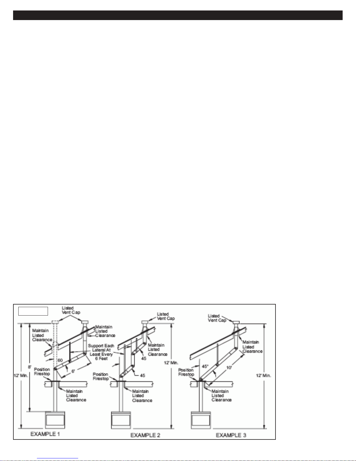
Venting Installation
Venting Installation
A “B-type” venting system must be connected to the
appliance for venting to outside of building. The following
section is provided as a guide to a standard B-type vent
installation.
Standing codes requirements concerning B-type vent
installations may vary within your state, province or local codes
jurisdiction. Therefore, it is recommended that you check with
your local building codes for specifi c requirements or in absence
of local codes, follow Section 7.0 of the current National Fuel
Gas Code ANSI Z223.1/NFPA 54 for Category I systems using
double wall B-1 vent pipe.
This gas appliance must be vented to the outdoors only
and may not be terminated into an attic space or into a chimney
fl ue servicing a solid fuel burning appliance.
This appliance may be vented through a manufactured
chimney system or a masonry chimney using a B-vent adapter
or a chimney liner system if the system is listed, inspected
and approved by local codes and/or building authorities. The
examples shown in Fig. 2 are typical of most B-vent installations
and codes practices.
Example 1: Shows the minimum allowable system height and
lateral offset for an inclination of 60° or greater.
Code specifi es that offsets of 60° or greater are considered
horizontal and must follow the 75% rule for lateral to total
vertical system height.
Codes also allows only one offset in the total system when
at 60° or greater.
The total vertical height in this example represents the
minimum height of 8 ft. and therefore the allowable lateral is 6
ft. when the 75% rule applies.
If the lateral length must exceed 75% then the system must
be sized in accordance with the Category I venting tables.
Example 2: Shows a multiple offset each at a 45° inclination.
Multiple offsets are permitted if they do not exceed a 45°
inclination. The total lengths of the two offsets are not required
to meet the 75% allowable rule.
Example 3: Shows a single offset at 45° of inclination and
therefore the lateral length at 10 ft. of offset does not have to
meet the 75% rule.
In each case the offsets must be supported and fi restops
must be positioned wherever the vent must pass through a
sub-fl oor, ceiling joist or an attic overhang.
The vent pipe must terminate vertically into a listed type
vent cap and extend a suffi cient height through an approved
roof fl ashing, roof jack or a roof thimble. At all points the listed
clearances must be maintained.
Vent terminations must be located in accordance with
height and proximity rules of NFPA No. 54.
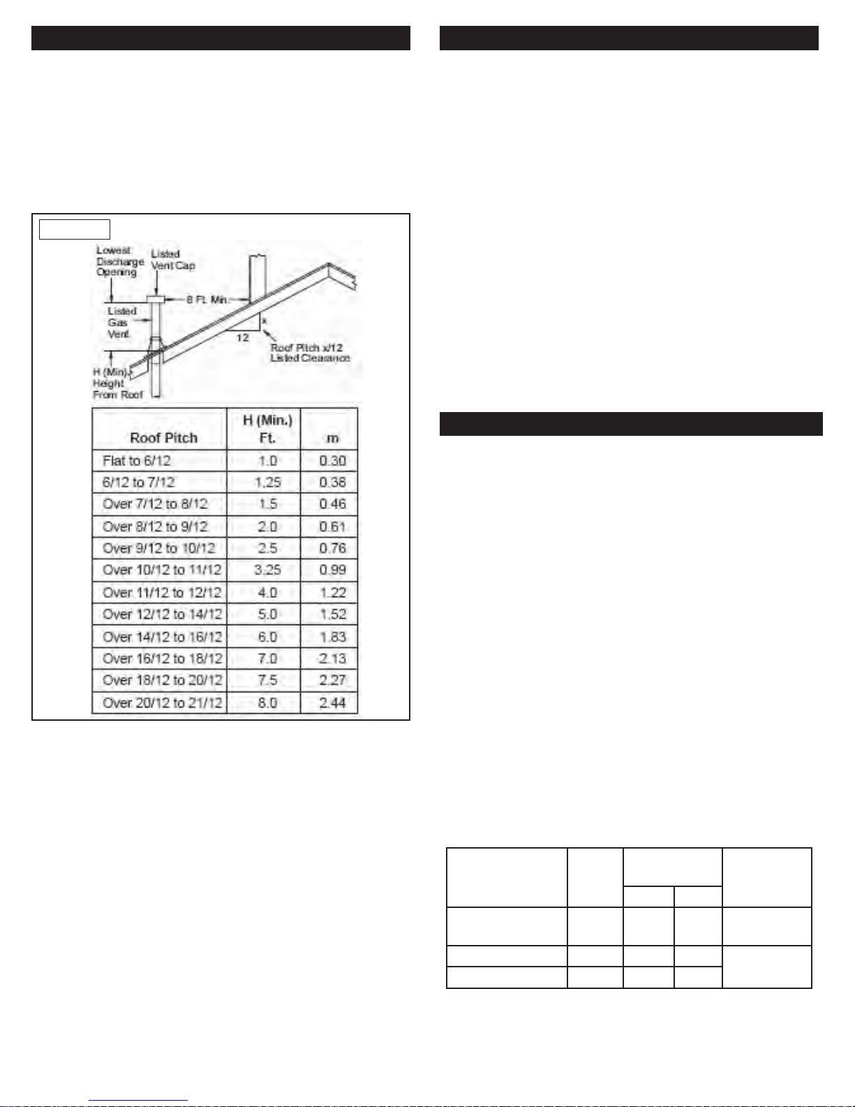
These rules apply to vents at 12” diameter or less and
require a minimum height in accordance with the roof pitch and
a minimum of 8 ft. distance from a vertical wall or obstruction
(see Fig. 3).
If venting horizontally through a side wall becomes
necessary, a listed thimble approved for use with B-type vent
must be used. Check with your local codes before venting
through a side wall.
Some codes areas allow the use of existing B-type vent
systems if the system is at or above the recommended diameter
of the fl ue.
The fl ue connection must be made using listed B-type
connectors and the existing system must be code inspected
for damage and proper installation.
It is not recommended that this appliance be common
vented with an existing gas burning appliance. However, if it
becomes necessary to common vent this appliance, the venting
system must be sized and confi gured in accordance with the
common venting guides Appendix G of the current National
Fuel Gas Code NFPA No. 54/ANSI Z223.1.
Note: Before connecting this appliance to an existing vent
system or a common venting system, consult with your local
architect, planner, or building offi cial.
Figure 2
16
Page 19
Specifying Chimney Heights
Specifying Chimney Heights
Chimney Termination Units
Important Pre-installation Information
If the horizontal distance from the mid-point of the chimney
to the peak of the roof ridge is less than 10 feet, the top of the
chimney must be at least 2 feet above the roof ridge. This is
called the “2 foot in 10 foot” rule.
If the horizontal distance from the chimney’s center
measured across to the ridge of the roof is more than 10 feet,
the top of the chimney still needs to be at least 2 feet above a
point measured from a distance of 10 feet horizontally along
the roof.
Figure 3
Chimney Termination Units
You will be installing at or possibly near the top of the
chimney chase fl ashing. A top termination unit is the essential
piece of equipment in keeping sparks out of the atmosphere.
Before installing this important piece of equipment, you will have
to make a judgment call as to whether or not the termination
unit – like all the other exterior exposed chimney components,
for that matter – should be painted in order to protect it/them
from rusting and weathering. Particularly if you are installing
the fi replace and chimney near water or in a high humidity area,
the manufacturer recommends a top quality, rust-proof paint
especially formulated for metal. Follow the paint manufacturer’s
directions, applying the paint well before you are scheduled to
install the round top termination unit or any of the fl ashings or
fl ues that will be exposed to outside weather conditions.
Venting terminals shall not be recessed into walls or siding.
This appliance, when installed, must be electrically grounded
in accordance with local codes and in the absence of local
codes, with the National Electrical Code, ANSI NFPA 70, or the
Canadian Electrical Code, CSA C22.1.
Important Pre-installation Information
Before you begin, review the information and safeguards
below regarding the installation and operation of the gas
Fireplace.
This fi replace may only be connected to the gas supply
listed on the label. Never use propane gas in a gas fi replace
designed for natural gas or natural gas in a gas fi replace
designed for use with propane gas.
Though there are many confi gurations in meeting these
requirements, chimney height cannot be less than 3 feet above
the roof at the edge of the chimney.
If the roof is fl at, the chimney must extend no less than 3
feet from where it intersects the roof. If the chimney is entering
the roof at an angle, measure the shorter angle where the
chimney intersects the roof which should be at least 3 feet.
Note: The previous guidelines do not take into consideration
outside conditions which may require a higher chimney due
to foliage, other buildings, power lines and weather conditions
in your area. Follow the chimney manufacturer’s installation
guide for further information.
The gas fi replace must be installed by an MFI Certifi ed or
other qualifi ed professional installer. The installation, including
provisions for combustion and ventilation air, must conform
with local codes, or, in the absence of local codes, with the
latest edition of the National Fuel Gas Code, ANSI Z223.1, and
NFPA54.
Keep the fi replace area clear and free from combustible
materials, gasoline, and other fl ammable vapors and liquids.
The fi replace must have a gas supply line that has been
installed by a qualifi ed technician in accordance with all local
codes.
The gas supply line must be 1/2” minimum interior diameter. If
the gas line to the fi replace is longer than 5’, a larger diameter
line may be necessary.
Burner P/N
GML-24-01(N)(P) 60 28/48 47/56 MGFP-39 or
GML-30-01N 90 19/41
GML-30-01P 84 40/55
BTU*
(x 1000)
Orifi ce Drill
Size (top/front)
Nat LP
Included in
-44
MGFP-49
*Nominal BTU based on gas inlet pressure. Nominal gas inlet
pressure for natural gas is 5” W.C.
17
Page 20
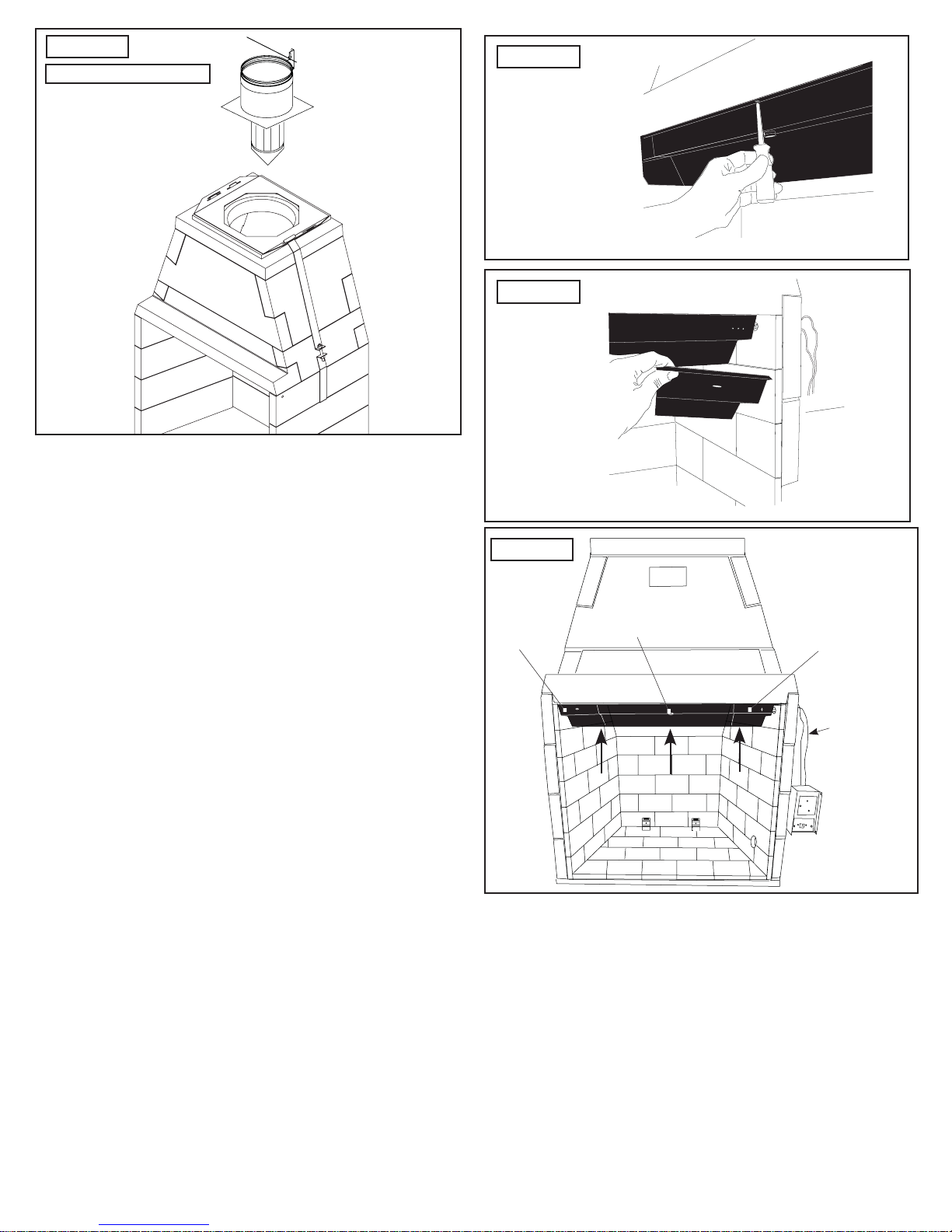
Figure 27
Vent Plate Installation
Attention: Clearance to combustible construction can not be
reduced during course of construction. For the safe operation of
the fi nished fi replace, these clearances must be followed when
building the framework to house the chimney system.
Figure 28
Figure 29
Installing the valve/control box assembly
Fasten the valve/control box assembly to a stud such that
1.
the control switch is facing in the desired direction and
fl ush with the future location of the fi nished wall or other
enclosure.
Install the two ‘D’ batteries into the battery holder within the
2.
control box.
Run the wires for the spill switch through the small hole
3.
in the upper wall. Important: This control box must remain
accessible and removable for service after installation.
Installing Spill Switch and Baffl e assembly
Connect the blade connectors on the spill switch wires to
1.
the matching wires from the valve/ control box assembly
coming through the upper hole in the fi rebox.
Center the black steel baffl e with the spill switch sensor
2.
pointed toward the room (out of the fi replace).
Use six (6) drywalls screws to fasten it in place on the front-
3.
most part of the fi rebox ceiling as shown through the six (6)
pre-drilled holes.
Attach the trim plates to the left and right side of the baffl e
4.
with the sheet metal screws so that the edges are fl ush with
the fi rebrick.
Figure 30
Trim
plate
Spillover
switch
Trim
plate
Spill sensor
wires to
valve/
control box
Owner’s Operation & Precautions
Installers of the Mason-Lite are urged to call the attention of
fi replace owners to the following precautions.
The installer should hand-deliver this owner’s manual to the
owner or leave behind with the unit after it the installation is
complete.
Important: This baffl e assembly and only this the supplied
assembly (with spill switch) must be properly installed for
the safe operation of this gas fi replace.
Warning: Use only the included fi replace grate or manufacturer
approved replacement.
Warning: Do not attempt to operate your fi replace without a fi re
safety screen installed.
18
Page 21
CAUTION: Use only the logs that come with this gas fi replace.
O
U
T
IN
PI
L
O
T
IN
The manufacturer cautions against using chemical chimney
cleaners. Never burn solid fuel in this fi replace under any
circumstance.
First Lighting of the Mason-Lite – After construction is
1.
completed, all elements of the fi replace and chimney
system must be completely dry. This means that the unit
must stand without any fi ring for a minimum of 28 days.
Only after that period of time can a fi rst lighting take place.
Do not let the fi re burn for more than one hour. After this fi rst
lighting – when the fi replace has started to “cure” Do not set
another fi re for at least 24 hours.
Second Lighting – With the second lighting you can let the
2.
fi re burn two hours – no more.
After First and Second Lighting – When the fi replace has
3.
been properly cured with careful “maiden” fi rings, you will
be able to run the burner for as long as you like.
Attaching the Burner and the Grate
Unpack the burner assembly and place the rear legs of
1.
the burner into the brackets in the back of the fi rebox (see
Figure 23).
Thread the pilot lines from the burner pilot assembly and
2.
through the hole in the lower side of the fi rewall to the valve/
control box assembly and attach to the valve.
Connect the supplied fl ex connector from the output of the
3.
valve, through the hole and to the burner.
Connect the second fl ex connector from the input of the
4.
valve to the gas stub down stream from the required
manual shut-off valve.
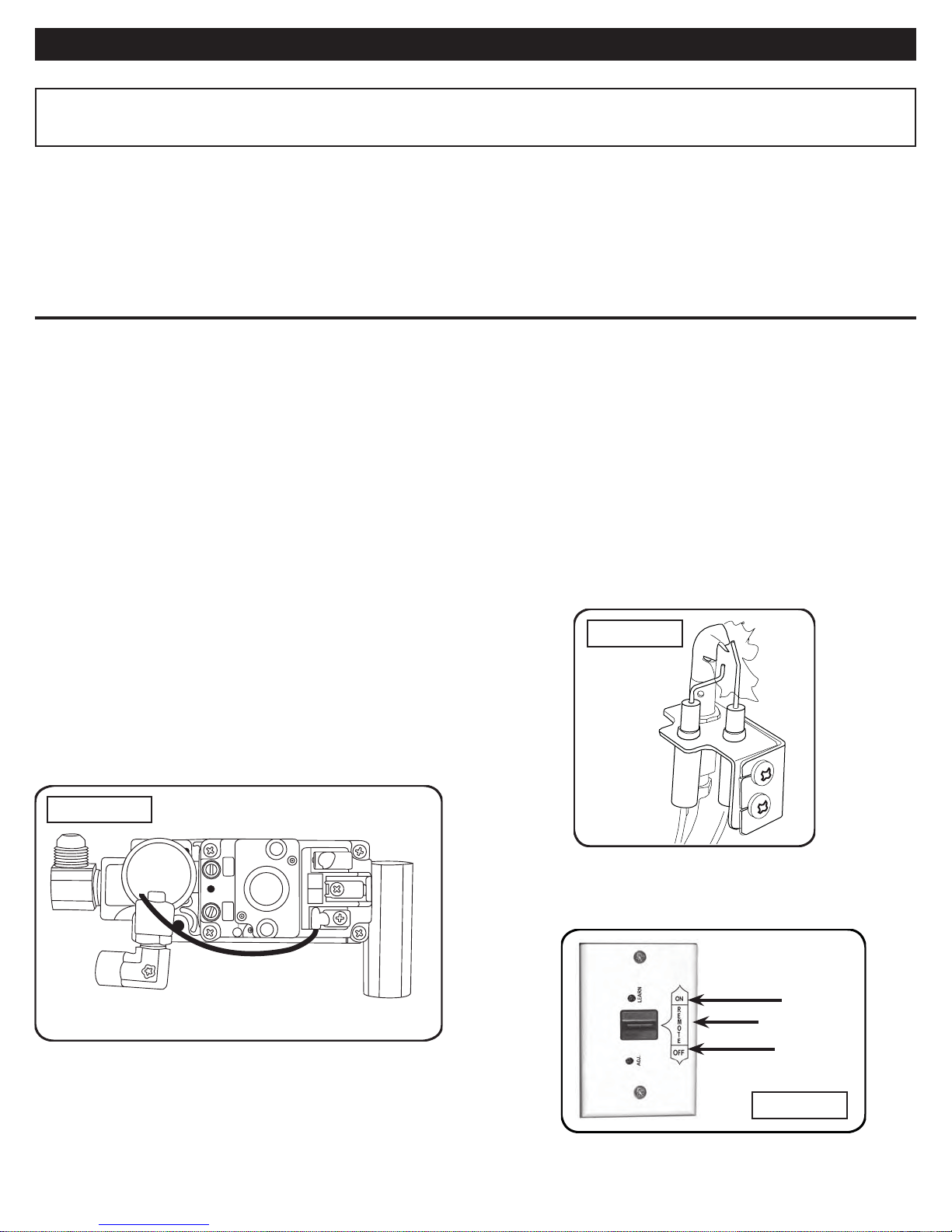
Note: The required 1/8” NPT up stream pressure tap is built
into the valve (Figure 33).
CAUTION: CHECK ALL CONNECTIONS FOR GAS LEAKS
USING A HALF-AND-HALF SOAPY WATER SOLUTION.
IF A LEAK IS DETECTED TIGHTEN CONNECTIONS AND
TEST AGAIN.
NEVER USE AN OPEN FLAME TO CHECK FOR GAS
LEAKS.
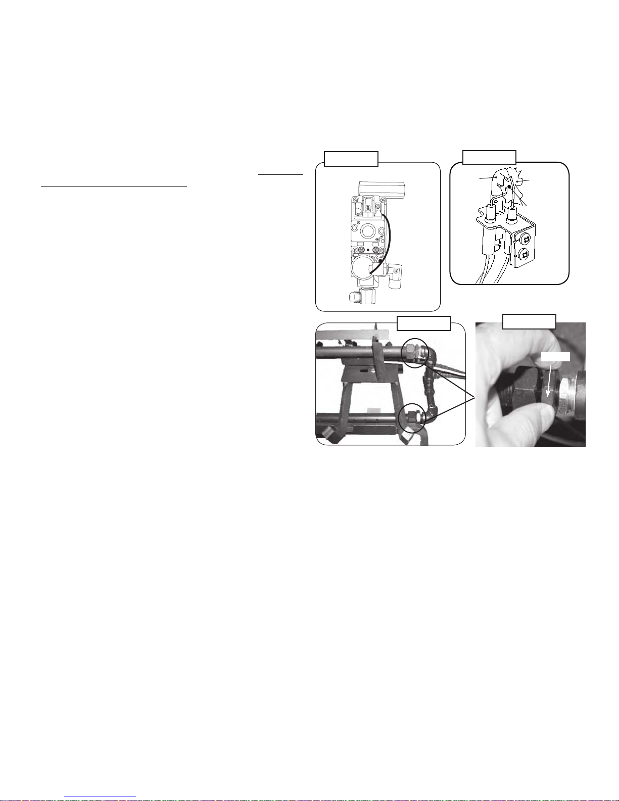
Checking and Adjusting the Pilot
1.
Follow the lighting instructions to light the pilot. The pilot
fl ame should encircle the generator tip which is preset at
the factory (Figure 32). Ordinarily, the pilot will not require
fi eld adjustment.
2.
If adjustment is necessary, remove the cap screw (Figure
32) and turn the smaller gas adjustment screw inside
counterclockwise to increase the pilot fl ame and clockwise
to decrease the pilot fl ame. Replace cap screw.
Figure 31
Figure 33
Note: This burner system is equipped with an APK-01 valve
assembly.
Placing the Decorative Lava Rock
If desired, open the bag of lava rock and pour its contents
around the base of the grating in an attractive pattern. Do not
place the Lava Rock on the logs or grate.
Figure 32
Pilot
Flame
Electrodes
Figure 34
Open
Insert a one-way screw into the hole in the front of each
5.
bracket and tighten with a long (min. 12”) screw driver until
contact is made with the grate leg and the grate is permanently
locked in place (see Figure 23).
IMPORTANT: Once installed the burner cannot be
removed.
Fill in the holes you have drilled around the gas piping with
6.
the regular MASON-LITE mortar.
Adjusting Air Mixers
Burners are equipped with air mixers for the top and front
burners. Adjust the size and color of the fl ame by opening (turn
outward) or closing (turn inward) as shown in Figure 33, 34.
19
Page 22
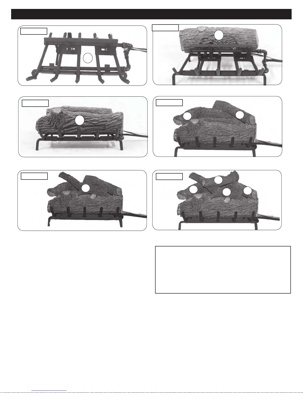
Log Placement
Log Placement
Figure 35
Start with the grate/burner assembly in place
Figure 37
1
11
Place front bottom log
GML-24 shown
Figure 36
Figure 38
10
Place back bottom log
9
Place back top logs (#8 and #9)
8
Figure 39
7
Place front top log (#7) All logs in place
Placing the Logs
Place the back bottom log on the grate behind the top burner
1.
and as far forward (against the top burner) as possible
without touching the pilot. The fl at side should be down and
the heat chambers facing the back of the fi replace (Figure
35).
Place the front log on the grate in front of the top burner
2.
pipe with the fl at down and the heat chambers toward the
burner pipe and the log as far forward as possible while
keeping the back parallel with the burner pipe (Figure 36).
Place top logs across the front and back logs in the order
3.
and positions shown in Figure 40.
Figure 40
9
6
7
WARNING
Failure to position the parts in
accordance with these diagrams or
failure to use only parts specifi cally
approved with this appliance may result
in property damage or personal injury.
8
20
Page 23
O
U
T
I
N
P I
LO T
IN
Lighting and Operating Instructions
Lighting and Operating Instructions
FOR YOUR SAFETY, READ BEFORE LIGHTING
WARNING: If you do not follow these instructions exactly, a fi re or explosion may result causing property
damage, personal injury or loss of life.
Do not use this gas fi replace if any part has been underwater. Immediately call for a qualifi ed professional service technician to
inspect the fi replace and to replace any part of the control system and any gas control which has been under water.
The Mason-lite burner system has a pilot which can be lit by hand using a match or lighter. When lighting the pilot, follow these
instructions exactly.
BEFORE LIGHTING, smell all around the burner area for gas. Be sure to smell next to the fl oor as some gas is heavier than air
and will settle on the fl oor. IF YOU SMELL GAS, FOLLOW THE INSTRUCTIONS ON THE COVER (P. 1).
TO LIGHT THE FIREPLACE WITH THE WALL
SWITCH
Move the ON-REMOTE-OFF wall switch to the ON position
(Figure 41). This transmits a rapid series of sparks at the pilot
head and will ignite the gas.
TO SHUT DOWN THE GAS FIREPLACE USING THE WALL
SWITCH
Move the switch to the OFF position (Figure 41). The gas fl ow
will cease, and all fl ames (main burner and pilot) will go out (see
important note below).
OPERATING THE BURNER USING THE REMOTE
Move the wall switch to the REMOTE position and follow the
instructions included in the remote kit for lighting and shutting
down the attached burner.
IMPORTANT: Do not allow the fi replace opening to be
blocked in any way while operating the fi replace. The
fi replace may be operated with a Mason-Lite screen installed
and drawn.
MAINTAINING THE PILOT
Your gas fi replace is equipped with a safety pilot that will shut
off the gas supply in case the pilot is not burning or functioning
properly. Regularly verify that the pilot is adjusted properly with
the pilot fl ame hitting the electrodes as shown in Figure 42. If the
pilot will not stay lit, call your local gas utility or gas supplier.
TO CHECK UPSTREAM GAS PRESSURE
Unscrew the four (4) screws above and below the control panel
face, then pull the control panel out far enough to expose the
test ports on the valve (Figure 41). Unscrew the port marked IN
part way and test.
CAUTION: Do not kink the fl ex connectors coming from the
valve while accessing it.
Figure 42
Lighting
the Pilot
Figure 41
Upstream gas
pressure tap
Note: Pilot fl ame should encircle top of electrodes.
See instructions cover for example of proper main burner fl ame
pattern.
ON
REMOTE
OFF
Figure 43
21
Page 24

Maintenance and Service
Maintenance and Service
Troubleshooting
Maintenance
Once installed and operating properly, the Mason-lite gas
fi replace requires very little maintenance.
You should inspect the fi replace, chimney, burner and control
annually for the following:
Excessive Sooting - Some sooting of the logs is normal
1.
and adds to the natural appearance of burned wood. If soot
accumulates, you may brush the soot off with a stiff brush.
Logs may also be cleaned by allowing them to heat up, then
spraying them with water where soot has accumulated.
Debris around the control - Inspect the control and pilot to
2.
be sure it is free of any dirt or debris.
Insects and burner blockage - Check the burner ports
3.
and the air-mixer, if present, to make sure they are free
from debris. Blocked burner ports and orifi ces may
result in poor fl ame distribution or fl ame at air mixer (if
equipped). Reference SOLUTION, to symptoms 2-4, of
Troubleshooting.
Troubleshooting
PROBLEM CAUSE SOLUTION
a. Pilot generator may not be producing
suffi cient millivolts.
b. Pilot fl ame making a blowing sound b. Pilot needs adjusting (see “Checking and
Pilot will NOT stay lit.1.
2. Pilot Burning.
No Gas to Burner.
3. Fireplace Not burning
properly.
4. Fireplace will not shut
OFF.
5. Frequent pilot outage.
6. Fireplace shuts down
during operation.
7. Excessive soot on logs.
c. Generator wire leads attached to the
wrong terminals on the valve.
d. Defective thermo-magnetic safety in
valve.
a. Safety valve not turned to the ON position
after lighting pilot.
b. Wire leads are not properly connected to
valve or switch terminals.
c. Voltage to pilot generator too low. c. See section 1a above.
d. Defective valve. d. Replace valve.
a. Low fl ame/uneven fl ame. a. Check for low gas pressure; minimum
a. Control Switch lead wires to the valve
may be shorted together or on wrong
terminals.
a. Pilot fl ame is out of adjustment. a. See section 1b above.
b. Down drafts from the chimney,
extinguishing the pilot.
a. Improper venting causing spill switch to
trip repeatedly.
b. Spill switch improperly mounted. b. See section on “Installing Spill Switch and
c. Smoke Diverter not in place. c. Install Smoke Diverter with Spill Switch per
a. Yellow fl ame impingement. a. Open air shutter on front burner or main
Service
It is recommended that a qualifi ed professional service
technician be called to service the gas fi replace and its venting
system at least annually or should service be required. More
frequent cleaning may be required due to excessive lint from
carpeting, bedding material, etc.
It is imperative that control compartments, burners and
circulating air passageways of the appliance be kept clean.
The Troubleshooting section of these instructions serves as a
guide for ensuring optimum performance of the gas fi replace.
Flame Appearance
The fl ames should be blue at the base and a combination of
blue/yellow at the body and tips.
a. Check with a millivolt meter. Should be 250
millivolts or more.
Adjusting the Pilot” on page 22).
c. Connect leads per wiring diagram, previous
page.
d. Replace valve.
a. Turn to ON position.
b. Attach all wire leads tightly to proper terminals
(See wiring diagram, previous page).
operating pressures of 5” W.C. at manifold.
a. See wiring diagram, previous page. System
takes 15-20 seconds to complete shutdown
(nominal).
b. Check draft. Consult with a qualifi ed chimney
expert.
a. Check draft. Consult with a qualifi ed chimney
expert. Consider installing a combustion air
kit.
Baffl e Assembly” on page 21.
instructions.
burner as needed.
22
Page 25
)
c
(f’
a
used to
c
c
d
d,e,f
3,000
3,500
b
, shall be as
c
f’
d
d,e,f
Weathering Potential
2,500 3,000
Negligible Moderate Severe
MINIMUM SPECIFIED COMPRESSIVE STRENGTH
support foundation for the fireplace installed on concrete shall
Appendix I
TABLE R402.2 MINIMUM SPECIFIED COMPRESSIVE STRENGTH OF CONCRETE
consist of a minimum of 6 inches thick reinforced concrete slab. The minimum specified compressive strength of
required in Table R402.2 of the International Residential Code (IRC). Concrete subject to moderate or severe weathering as indicated
For installations regulated by the International Residential Code, the
in Figure R301.2(3) of the International Residential Code (IRC) shall be air entrained as specified in Table R402.2 of the International
Residential Code (IRC). The maximum weight of fly ash, other pozzolans, silica fume, slag or blended cements that is included in
produce concrete and testing thereof shall comply with the applicable standards listed in Chapter 3 of ACI 318.
shall not exceed the percentages of the total weight of cementitious materials specified in Section 4.2.3 of ACI 318. Materials
concrete mixtures for garage floor slabs and for exterior porches, carport slabs and steps that will be exposed to deicing chemicals
accordance with Footnote d.
c. Concrete in these locations that may be subject to freezing and thawing during construction shall be air-entrained concrete in
a. Strength at 28 days psi.
b. See Figure R301.2(3) for weathering potential.
d. Concrete shall be air-entrained. Total air content (percent by volume of concrete) shall be not less than 5 percent or more than
TYPE OR LOCATION OF CONCRETE CONSTRUCTION
For installations regulated by the International Building Code (IBC), the support foundation for the fireplace installed on concrete
1903, 1904 and 1905 of the International Building Code (IBC).
shall consist of a minimum of 6 inches thick reinforced concrete slab. The concrete strength and durability shall comply with Sections
Basement walls, foundations and other concrete not exposed to the weather 2,500 2,500 2,500
Basement slabs and interior slabs on grade, except garage floor slabs 2,500 2,500 2,500
work exposed to the weather
Basement walls, foundation walls, exterior walls and other vertical concrete
Porches, carport slabs and steps exposed to the weather, and garage floor slabs 2,500 3,000
23
7 percent.
3 percent is permitted if the specified compressive strength of the concrete is increased to not less than 4,000 psi.
e. See Section R402.2 for maximum cementitious materials content.
f. For garage floors with a steel troweled finish, reduction of the total air content (percent by volume of concrete) to not less than
Page 26
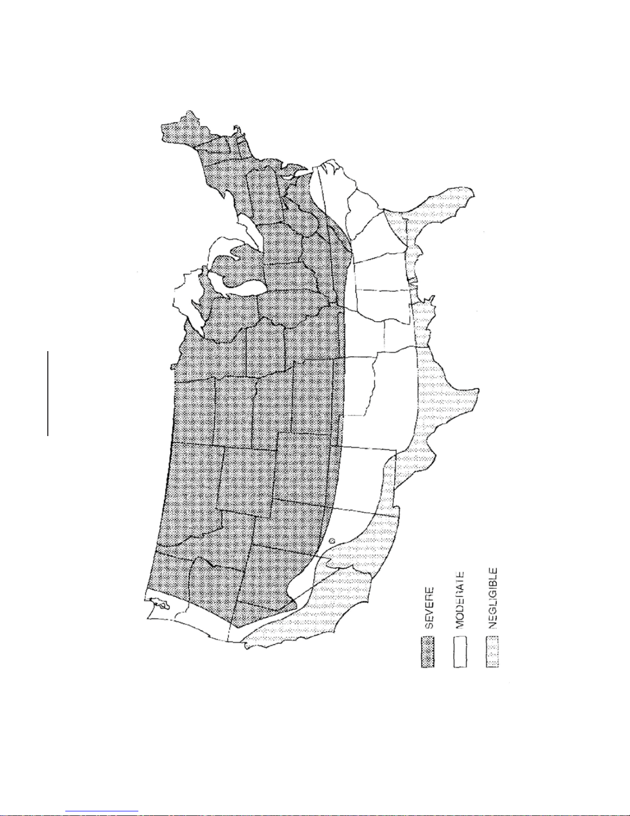
Appendix II
FIGURE R301.2(3) WEATHERING PROBABILITY MAP FOR CONCRETE
24
a. Alaska and Hawaii are classified as severe and negligible, respectively.
severe classification is where weather conditions result in significant snowfall combined with extended periods during which there is
b. Lines defining areas are approximate only. Local conditions may be more or less severe than indicated by region classification. A
little or no natural thawing causing deicing salts to be used extensively.
Page 27

Limited Warranty
Mason-Lite™ Fireplace
Masonry Fireplaces Industries, LLC (MFI) warrants all MASON-LITE Fireplaces to be free from defects in materials that
adversely affect fi replace performance for a period of ten (10) years from the date of purchase, subject to the terms and
conditions of this limited warranty. MFI does not warrant accessory chimney, outside air ducts, gas control or burner
system, ceramic logs, and devices not manufactured by MFI. Valves and electronic parts are only covered for one year
parts and labor per the log set manufacturer’s warranty. The manufacturer’s warranty for the gas log set is fi ve (5) years
and the electronic ignition and valve is for one (1) year.
This warranty covers only products manufactured by MFI, specifi cally the modular concrete fi rebox, and NO WARRANTY,
EXPRESS OR IMPLIED, EXTENDS TO ANY OF THE HARDWARE, FOUNDATION, VENTING, DUCTS, OR
ACCESSORIES. THIS WARRANTY DOES NOT COVER DRAFTING, SMOKING, OR SOOTING OF THE FIREPLACE
SYSTEM. Factors beyond the manufacturer’s control may affect drafting, smoking, and sooting, MFI cannot guarantee
these aspects of performance.
If a component is found to be defective under the terms of this warranty, the party this warranty is extended to shall
notify MFI, 315 W. 3rd Street, Santa Ana, CA 92701 in writing, by registered mail, within thirty (30) days following the
discovery of the defect within the warranty period. The letter shall contain (1) the date of purchase; (2) place of purchase;
(3) address of installation; (4) name, address and phone number of the homeowner; and (5) a brief description of the
defect.
MFI, or any entity thereof, is not responsible for any labor costs or indirect costs incurred for the replacement of
defective components.
MFI is not responsible for misuse or mishandling of component parts. Nothing in this warranty makes MFI, or any
entity thereof, liable in any respect for any injury or damage to the building or structure in which the fi replace has been
installed or to the persons or property therein arising out of the use, misuse, or installation of properly manufactured
MFI product.
MFI, OR ANY ENTITY THEREOF, SHALL NOT BE HELD LIABLE FOR ANY INCIDENTAL OR CONSEQUENTIAL
DAMAGES OR EXPENSES ARISING OUT OF THE USE OF THE FIREPLACE. ALL SUCH DAMAGES AND EXPENSES
ARE HEREBY EXCLUDED.
This warranty is null and void when the fi replaces are not installed pursuant to the installation instructions provided by
MFI and local building codes have not been followed completely.
This warranty applies only to those fi replaces installed in the continental United States, Hawaii, Alaska and Canada. If
any part of this warranty is found to be unenforceable,, the remaining parts shall remain in force and effect.
MFI HEREBY DISCLAIMS ALL GUARANTEES AND WARRANTIES, EXPRESS OR IMPLIED, BEYOND THE
WARRANTIES SET FORTH HEREIN.
CUSTOMER SERVICE & PARTS REPLACEMENT:
Parts and accessories may be purchased from your local dealer. Additional information is available from Masonry
Fireplace Industries, L.L.C. Accessory orders will be accepted by mail, or you may call to order Monday through Friday
from 1:00 p.m. to 5:00 p.m. (Pacifi c Standard Time) at: (800) 345-7078.
Please complete the following information for future reference and warranty verifi cation:
Date of Purchase ____________________20____
Model # ________________
Serial # ________________
Masonry Fireplace Industries, LLC
315 West 3rd Street Santa Ana, CA. 92701
 Loading...