

Page 1
3/4" (19 mm)
1/4"
(6.3 mm)
2"
(51 mm)
Barn Door Installation Guide
BARN DOOR HARDWARE TOP MOUNT KIT
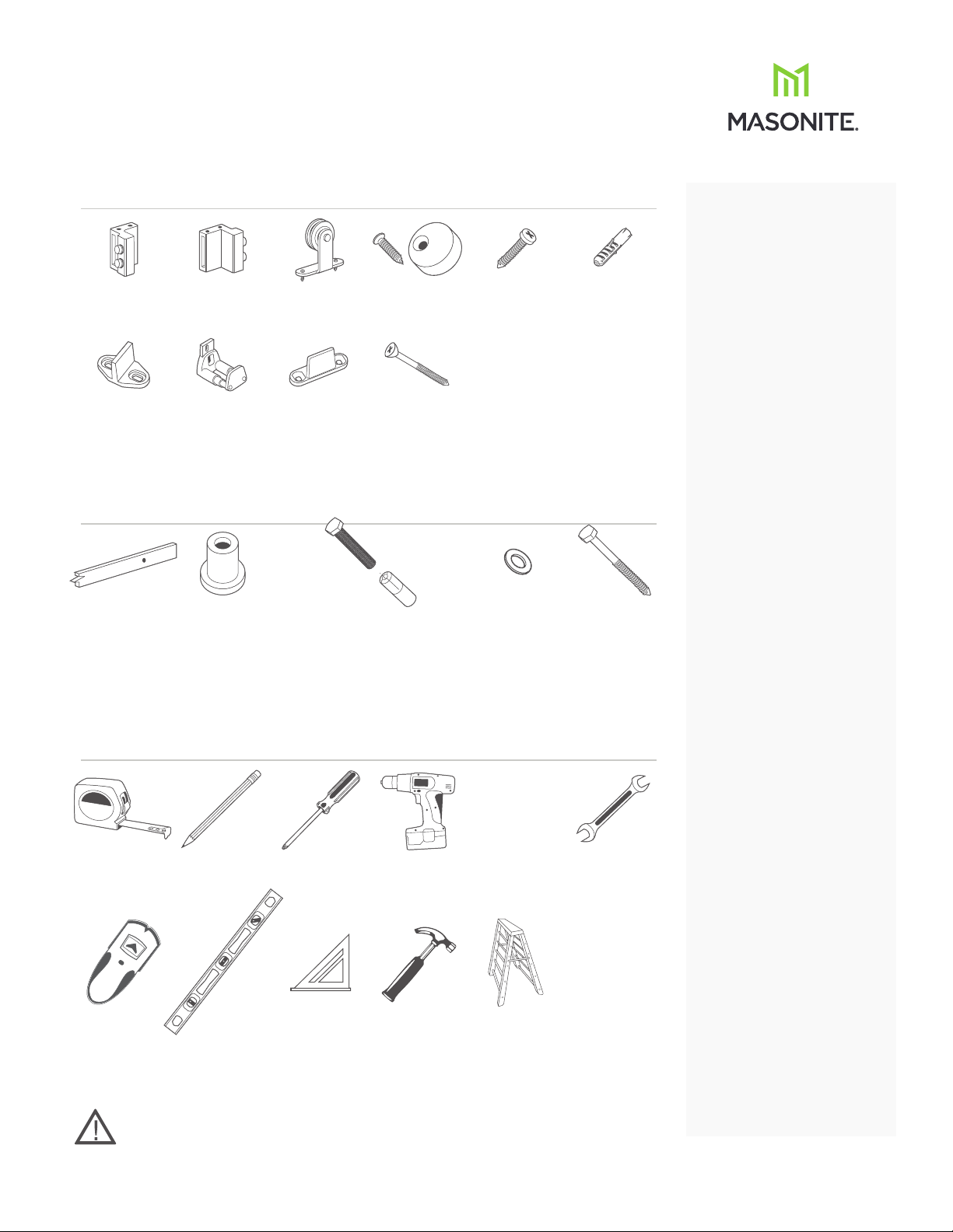
COMMON COMPONENTS
1x
Right
Stopper
1x
Intern al
Floor-Mounted
Door G uide
1x
Left
Stopper
1x
Wall-Mounted
Door Guide
Optional
2x
Top Mount
Roller
2x
Floor-Mounted
Door Guide
Optional
2x
Anti-jump
Block
# 10 x 2-1/2
Wood S crews
For mo unting
wood block for
drywall installation
2x
#8 (4.2mm x
25mm)
Floor S crews
2x
1/4 (6 mm)
Floor Anchor
IMPORTANT
BEFORE YOU BEGIN
Read instructions fully before
starting the installation of your
barn door. Not following the
installation instructions can
cause the unit to work in an
unsafe manner and cause injury.
The barn door kit has been
designed to work as a total
system. Any modification to the
door or the hardware will void
the warranty and may cause the
unit to work improperly.
TRACK COMPONENTS
1x
78 -3 /4" or 8 3-3/4"
Track (5 holes)
Track depending
on model
5x
Wall
Spacer
5/16 " (8mm x 6 0mm) Ca rriag e Bolt
5x
and 5/ 16" (8 mm x 25m m) Ancho r
(Pre-mounted to Carriage Bolt)
For concrete wall
installation only
Washe r
TOOLS REQUIRED
Tape Measure Pencil Phillips Screwdriver Cordless Drill Drill bit*
(1/8 ", 1/4", 5/16 "
and 3/8")
5x
3/8"
5x
5/16 "
(8mm x 9 0mm)
Track Mount
Lag Bolts
For drywall
installation with
wood blocking
Wrench
(13 mm)
The weight of the barn door
requires 2 people during
installation.
Always wear appropriate
personal protection equipment
when using tools and follow
manufacturer's operating
instructions.
When installing directly into
a non-concrete wall, do not
attempt to install the track solely
to the drywall or any wall surface
as this may not support the
weight of the track and mounted
door.
The track must be installed onto
a piece of solid wood blocking
using mounting screws (included
in some complete kits).
Ensure the solid wood blocking is
secured into
the structural surface.
Use a stud finder where
necessary to locate studs
and secure safely.
Stud Finder Level Speed Square Hammer Step Ladder
Look for Symbol to ID
important objective in step
NOTE: if installing i n concrete, masonry bits wil l be nee ded
* Depending o n mode l and mo unting appl icati on
Typical solid wood blocking
should be a 1"x4" solid wood
board the length of the track.
Warranty available on
Masonite.com.
©2021 Masonite International Corporation. RTL-21031 TM
Page 2
3/4" (19 mm)
1/4"
(6.3 mm)
3/4" (19 mm)
1/4"
(6.3 mm)
1/8” (3.5 mm)
Position rollers minimum
of 4” (101 mm) from edge
Drill Depth
XXX”
(XX mm)
Barn Door Installation Guide
BARN DOOR HARDWARE TOP MOUNT KIT
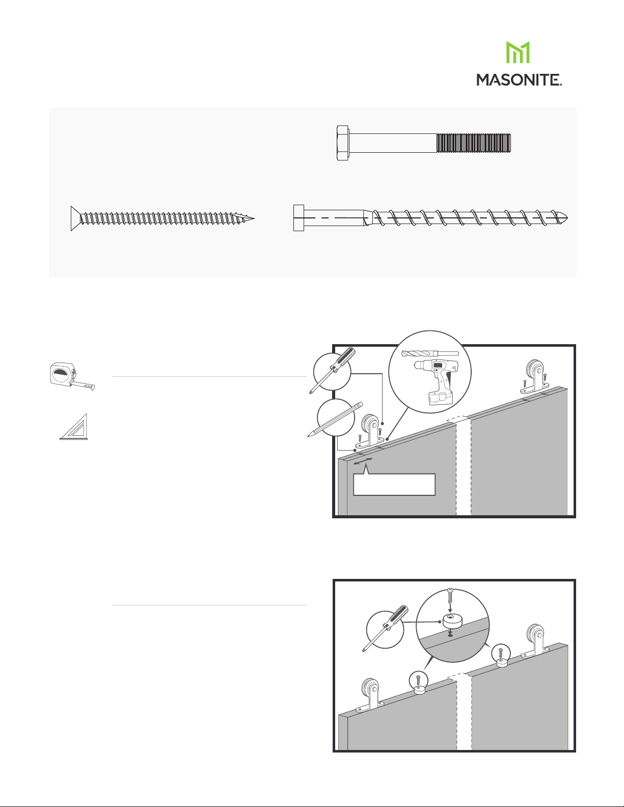
HARDWARE MATCH UP GUIDE
Refer to the following full scale hardware
drawings to quickly match up the hardware.
5/16" (8mm x 60mm)
Carriage Bolt
Tape Measure
Speed Square
# 10 x 2-1/2"
Wood Screws
ATTACHING ROLLER
1
TO DOOR PANEL
Position each roller 4" from the edge of the
door and centered.
Mark the first hole with a pencil and pre-drill
1/8" holes, then secure into place. Mark the
second hole with the roller in place to ensure
the roller is secure and straight on the door.
5/16" (8mm x 90mm)
Track Mount Lag Bolt
FIGURE 1. Roller Installation
1/8” (3.5 mm)
Drill D epth
Drill Depth
1"
XXX”
(25 m m)
(XX mm)
Position rollers minimum
Position rollers 4"
of 4” (101 mm) from edge
(101 m m) from th e edge
DOOR PREPARATION - ANTI-JUMP
2
BLOCK INSTALLATION
Position each anti-jump block at least 1" from
the edge of the rollers.
The hole for the anti-jump blocks should be
offset from the center of the door so the block
can be rotated out of the way to be able to
hang the door on the track. (FIGURE 2)
NOTE: For concrete wall installation
proceed to step 3. For Drywall
installation proceed to step 6.
FIGURE 2. Anti-jump blocks installation
©2021 Masonite International Corporation. RTL-21031 TM
Page 3
Track length
Door height + 1 3/4”
3” from
opening
3/8” (9.5 mm),
1/2” (12.7 mm)
gap under the
door
5/16” (8 mm)
Drill depth
1 3/8”
(30 mm)
Track length
Door height + 1 3/4”
3” from
opening
3/8” (9.5 mm),
1/2” (12.7 mm)
gap under the
door
Barn Door Installation Guide
BARN DOOR HARDWARE TOP MOUNT KIT
Tape Measure
Speed Square
Hammer
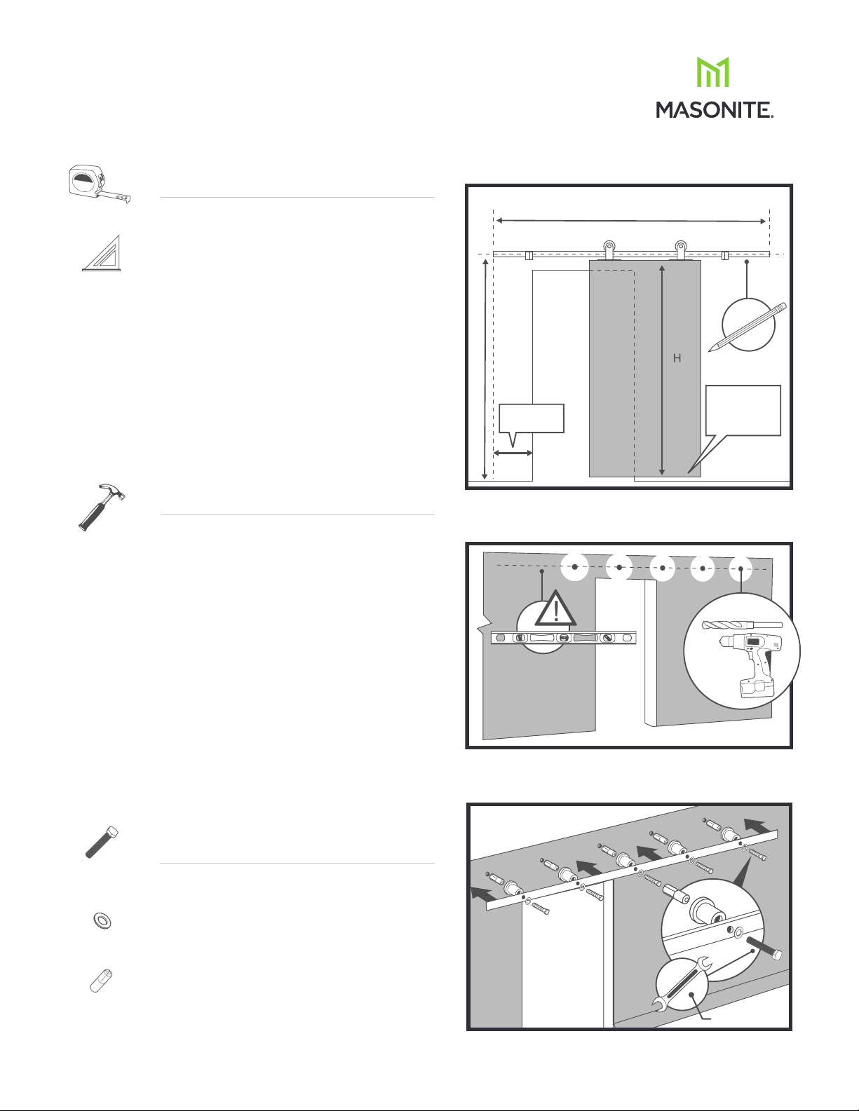
MARKING TRACK LOCATION FOR
3
CONCRETE WALL INSTALLATION
IF INSTALLING INTO DRYWALL PLEASE
PROCEED TO STEP 6.
Using a ladder, tape measure and speed square,
find the center line position of the track by
adding 1-3/4" to the door height and measuring
up from the floor. Mark with a pencil.
To find end location of the track, measure 3"
over from edge of opening. Mark with a pencil.
(FIGURE 3)
When installing with a standard 80" height
opening, the top trim will need to be removed
and the top of the side trim cut horizontally
along the height of the opening. (NOT SHOWN)
CONCRETE WALL
4
PREPARATION
Position the track in place using the marks in
previous step. Ensuring it is level and using
the track as a template, mark mounting hole
locations for the track using a pencil.
(FIGURE 4) See installation tip below.
Predrill the concrete at marked location using
5/16" masonry drill bit.
Remove metal anchors from bolts and install
into holes using a hammer. (FIGURE 5)
FIGURE 3. Locate the position of the track
Track length
Door height + 1 3/4”
3” from
opening
3/8 (9.5 mm),
1/2” (12.7 mm)
gap under the
door
FIGURE 4. Drilling mounting holes in concrete
5/16” (8 mm)
Drill depth
1 3/8”
(30 mm)
5/16 " (8mm x 6 0mm)
Carriage Bolt
3/8" Wa she r
5/16 " (8mm x 2 5mm)
5x
5x
5x
Anchor
INSTALLATION TIP: locate and temporarily
install track with one end bolt without spacer.
This will hold one end of the track up so you
can move the free end to ensure the track will
be level then proceed to mark
the other locations of mounting holes.
CONCRETE TRACK
5
PREPARATION
If installing Soft Close feature refer to
Soft Close instructions before mounting track.
Install track with bolts, washers and
spacers using 13 mm wrench. (FIGURE 5)
FIGURE 5. Track mount
13mm Wrench
©2021 Masonite International Corporation. RTL-21031 TM
Page 4
Track length
Door height + 1 3/4”
3” from
opening
3/8 (9.5 mm),
1/2” (12.7 mm)
gap under the
door
3/8” (9.5 mm),
1/2” (12.7 mm)
gap under the
door
Door height + 1 3/4”
3” from
opening
Track length
Solid wood
blocking
Track length
Door height + 1 3/4”
3” from
opening
3/8 (9.5 mm),
1/2” (12.7 mm)
gap under the
door
3/8” (9.5 mm),
1/2” (12.7 mm)
gap under the
door
Door height + 1 3/4”
3” from
opening
Track length
Solid wood
blocking
Framing material
(studs)
3/8” (9.5 mm),
1/2” (12.7 mm)
gap under the
door
Track length
Solid wood
blocking
Barn Door Installation Guide
BARN DOOR HARDWARE TOP MOUNT KIT
Tape Measure
Speed Square
DRY WALL
6
PREPARATION
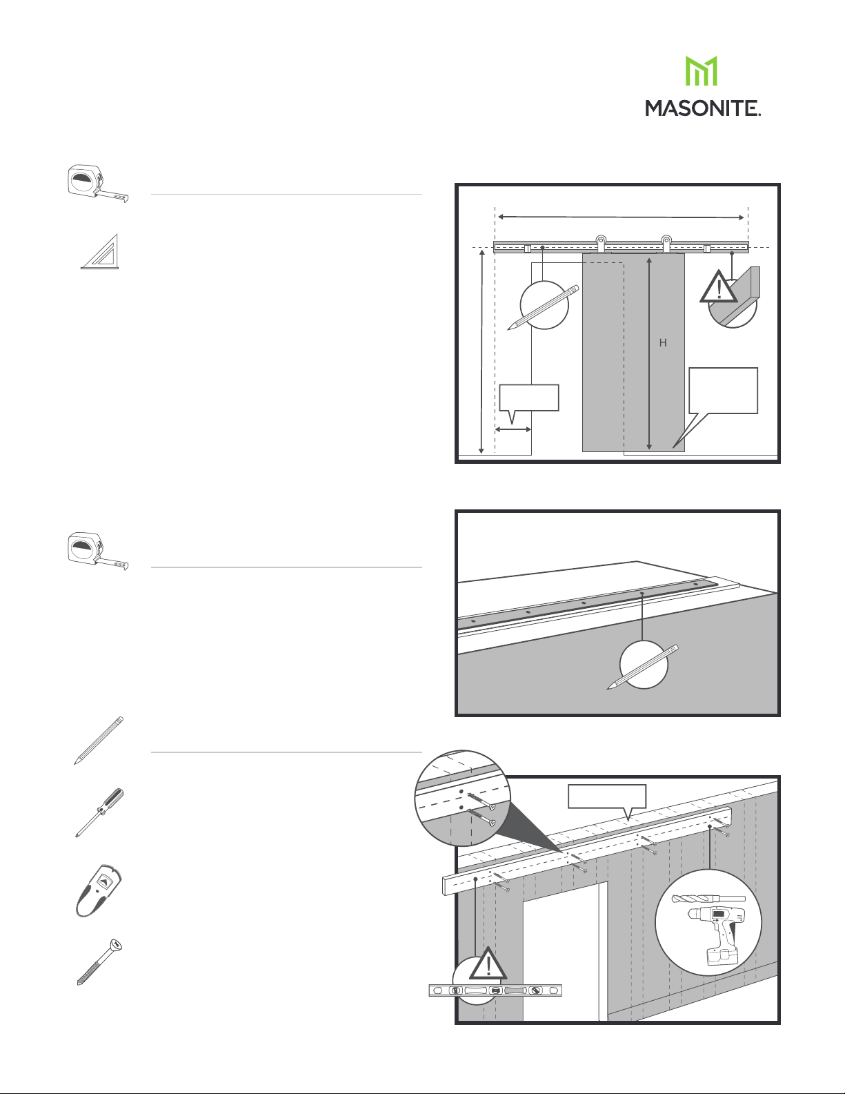
When installing on drywall or plaster, a 1x4
wood board must first be fastened to the
structural wall members (studs) behind the
drywall before mounting the track.
Using a ladder, tape measure and speed square,
find the center line position of the track by
adding 1-3/4" to the door height and measuring
up from the floor. Mark with a pencil.
To find end location of the track, measure
3" over from opening. Mark with a pencil.
(FIGURE 6)
NOTE: Mounting board to have same center as
track. End of mounting board may vary from
track end. See Step 7.
When installing with a standard 80" height
opening, the top trim will need to be removed
and the top of the side trim cut horizontally
along the height of the opening. (NOT SHOWN)
MARKING
7
MOUNTING HOLES
FIGURE 6. Locate the position of track and mounting board
Track length
Door height + 1 3/4”
3” from
opening
3/8 (9.5 mm),
1/2” (12.7 mm)
gap under the
door
FIGURE 7. Marking mounting holes on mounting board
Tape Measure
Pencil
Phillips
Screwdriver
Stud Finder
# 10 x 2-1/2
Wood S crews
On a flat surface, center the track on the
mounting board (insure the track is straight on
the board). Mark locations of track mounting
holes onto board. (FIGURE 7)
NOTE: If using the Soft Close feature, refer to
Soft Close instruction sheet before proceeding.
ATTAC H ING
8
MOUNTING BOARD
Use the stud finder to find the framing
material (studs) behind the drywall. Mark
locations. (Remember to mark location so
that you will be able to see them when
mounting 1x4 board.)
Position the mounting board on the wall
ensuring it is level. Attach through drywall
into studs using #10 x 2-1/2 screws (2 per
stud location). Predrill with 1/8” drill bit.
Position screws so they do not interfere
with track mounting holes. (FIGURE 8)
INSTALLATION TIP: Locate and install one
screw at end of board first. This will hold
one end of the board so you can move the
free end and ensure the board is level as
you install the other #10 x 2-1/2” screws.
FIGURE 8. Attaching mounting board to studs
Framing material
(studs)
1/8" (2" deep)
Drill depth
1 3/16"
(30 mm)
©2021 Masonite International Corporation. RTL-21031 TM
Page 5
3/8” (9.5 mm),
1/2” (12.7 mm)
gap under the
door
Door height + 1 3/4”
Minimum 2”
(51 mm)
81” x 5-1/2” x 7/8”
78 3/4” (2000 mm)
Solid wood
blocking
3/8” (9.5 mm),
1/2” (12.7 mm)
gap under the
door
Door height + 1 3/4”
Minimum 2”
(51 mm)
81” x 5-1/2” x 7/8”
78 3/4” (2000 mm)
Solid wood
blocking
Solid wood
blocking
3/8" (10 mm)
Drill depth
1 3/8"
(30 mm)
x2 Floor-mounted bottom guides
x4 #8 5/8" pan head philips screws
Barn Door Installation Guide
BARN DOOR HARDWARE TOP MOUNT KIT
5x
5/16 " (8mm x 9 0mm)
Track Mount Lag Bolts
MOUNTING
9
TRACK TO BOARD
Drill 1/4" dia pilot holes for track mounting lag
bolts into board at marked locations from
Step 7. (FIGURE 9)
ATTACHING TRACK
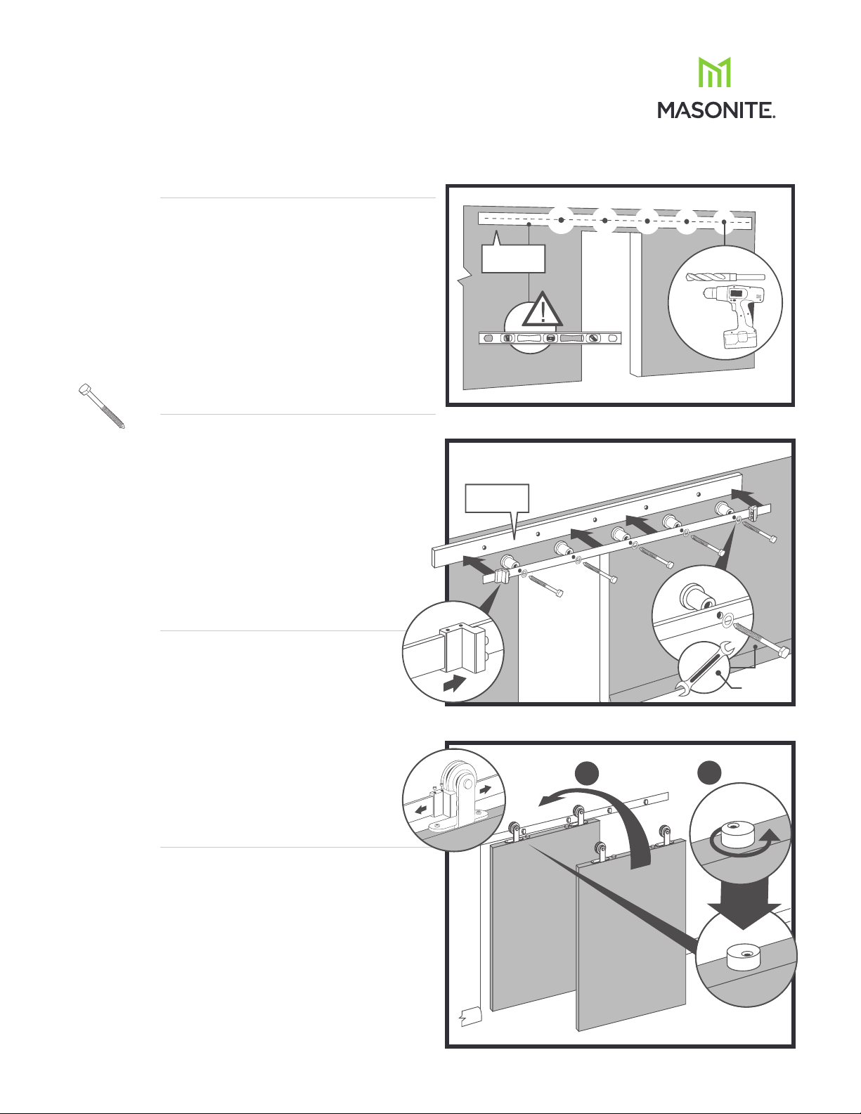
10
Attach track to mounting board with 3-3/4"
lag bolts with spacers and washers using
13 mm wrench. (FIGURE 10)
Washers can be found on concrete bolts.
TO MOUNTING BOARD
FIGURE 9. Drilling for track mounting lag bolts
Solid wood
blocking
1/4 " d i a
3/8" (10 mm)
Drill depth
1 3/8"
(30 mm)
FIGURE 10. Attaching track and installing stoppers
Solid wood
blocking
11
Slide stoppers on both ends of track
(note the stoppers are handed).
Secure with set screws using the allen
wrench that is included with stoppers.
12
Place assembled door with roller onto track
and rotate the anti-jump block. Slide door back
and forth to test how well the door covers
the opening. Reposition stoppers as needed.
(FIGURE 11)
If less travel of the door is required, the
stoppers can be moved inside end mounting
bolts. Remove the end mounting bolts and
spacers, slide the stopper to the new location
and reinstall bolt and spacer.
HANGING DOOR AND
ADJUSTING STOPPERS
13mm
Wrench
FIGURE 11. Hanging door and adjusting stoppers
1
2
©2021 Masonite International Corporation. RTL-21031 TM
Page 6
1/4" (8 mm)
Drill depth
1 3/16"
(30 mm)
Barn Door Installation Guide
BARN DOOR HARDWARE TOP MOUNT KIT
FLOOR-MOUNTED DOOR
13
GUIDE INSTALLATION
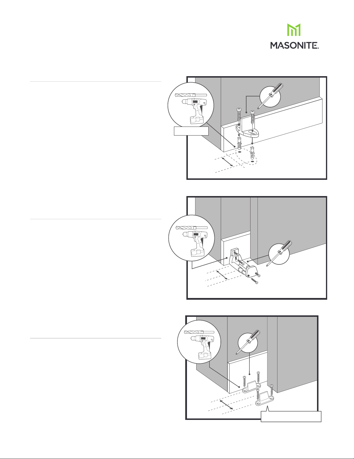
Used for standard doors that are grooved
in the bottom of the panel for the guide.
With the door hanging straight, position the floormount door guide inside groove in the bottom of the
door. Slide the door side to side to ensure the guide
is properly placed. Mark location of guide.
Attached guide with supplied screws. If needed,
supplied anchors can be used by drilling 1/4" dia
holes. (FIGURE 12)
To fasten guide, the door may need to be removed or
slide out of the way by loosening one of the stoppers.
If Soft Close units have been installed, refer to Soft
Close instructions for mounting activation brackets.
OPTIONAL WALL-MOUNTED
14
DOOR GUIDE INSTALLATION
The Wall-Mounted Guide can be used if the
floor condition makes it difficult to attach
the floor mounted guide.
Close to the opening, position and secure the
wall-mounted door guide directly into the wall or
trim, extending the guide as necessary to allow the
door to travel side-to-side. Tighten to secure in place.
NOTE: Adjust correctly for 1-3/8" or 1-3/4" thick
doors for smooth opening and closing operation.
FIGURE 12. Attaching floor mounted door guide
1/4" (8 mm)
Drill depth
1 3/16"
(30 mm)
IF NEEDED
FIGURE 13. Attaching optional wall mounted door guide
1/8" (3 1/2 mm)
Drill depth
1 3/16"
(30 mm)
To fasten guide, the door may need to be removed or
slide out of the way by loosening one of the stoppers.
ATTACHING OPTIONAL FLOOR
15
GUIDES USING SIDE METHOD
For custom doors that are not grooved on
the bottom, the side guides can be used.
Close to the opening, position both the floor-mounted
door guides to allow the door to travel side-to-side on
both sides of the door. Screw into place directly into
the floor.
Note: Measure correctly for 1-3/8" or 1-3/4" thick
doors for smooth opening and closing operation.
To fasten guide, the door may need to be removed or
slide out of the way by loosening one of the stoppers.
FIGURE 14. Attaching optional floor guides using side method
1/8" (4 mm)
Drill depth
1" (25.4 mm)
x2 Floor-mounted bottom guides
x4 #8 5/8" pan head philips screws
©2021 Masonite International Corporation. RTL-21031 TM
Page 7
x2 Floor-mounted bottom guides
x4 #8 5/8" pan head philips screws
Barn Door Installation Guide
BARN DOOR HARDWARE TOP MOUNT KIT
FINAL CHECK OF STOPPERS
16
AND ANTI-JUMP BLOCKS
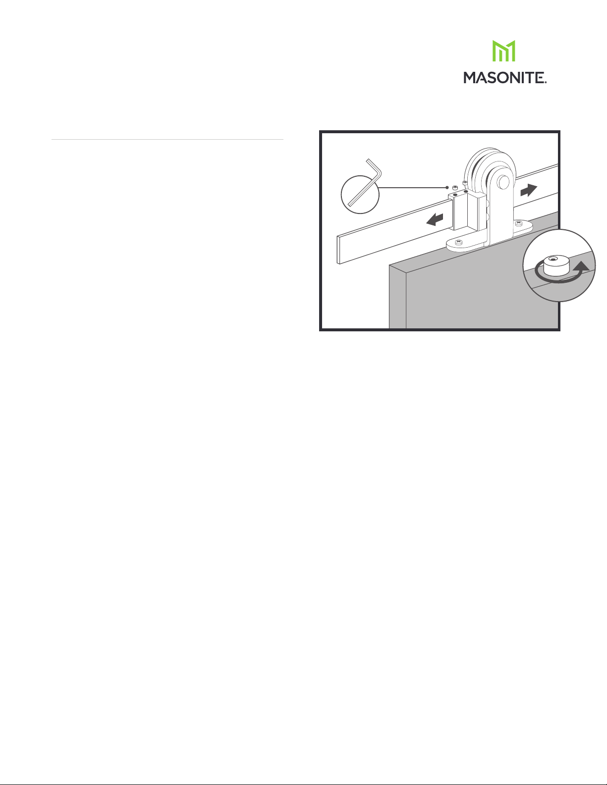
Check to see that stoppers are properly located and
tightened in place. Also check to see anti-jump blocks
are rotated correctly and tightened.
FIGURE 15. Securing stoppers and anti-jump blocks
©2021 Masonite International Corporation. RTL-21031 TM
 Loading...