

Page 1

Root®
Operator's Manual
Page 2

Page 3
For Sale in the USA
These operating instructions provide the necessary information for proper operation of all
models of the Root®. There may be information provided in this manual that is not relevant
for your system. General knowledge of pulse oximetry and an understanding of the features
and functions of Root are prerequisites for its proper use. Do not operate Root without
completely reading and understanding these instructions.
Notice: Purchase or possession of this device does not carry any express or implied license to
use with replacement parts which would, alone or in combination with this device, fall within
the scope of one of the relating patents.
Note: Cleared Use Only: The device and related accessories are cleared by the Food and Drug
Administration (FDA) and are CE Marked for noninvasive patient monitoring and may not be
used for any processes, procedures, experiments, or any other use for which the device is not
intended or cleared by the applicable regulatory authorities, or in any manner inconsistent
with the directions for use or labeling.
CAUTION: Federal (USA) law restricts this device to sale by or on the order of a physician. See
instructions for use for full prescribing information, including indications, contraindications,
warnings and precautions.
Wireless Radio
FCC ID:VFK-RDS7A IC:7362A-RDS7A IC Model: RDS-7A
Masimo Corporation
40 Parker
Irvine, CA 92618, USA
Tel.: 949-297-7000
Fax.: 949-297-7001
www.masimo.com
EU authorized representative for Masimo Corporation:
MDSS GmbH
Schiffgraben 41
D-30175 Hannover, Germany
Medical electrical equipment with respect to electric shock, fire, and
mechanical hazards only in accordance with
UL 60601-1/CAN/CSA C22.2 No. 601.1
Patents: www.masimo.com/patents.htm
PVi, Radical-7, rainbow, Root, RRa, SedLine, SET, Signal Extraction Technology, SpCO, SpHb,
SpMet, Masimo and , are federally registered trademarks of Masimo Corporation.
Iris, ISA, MOC-9, MyView, Radius-7 and SpOC are trademarks of Masimo Corporation.
The use of the trademark Patient SafetyNet is under license from University HealthSystem
Consortium.
All other trademarks and registered trademarks are property of their respective owners.
© 2017 Masimo Corporation
www.masimo.com 1 Masimo
Page 4

Page 5

Contents
About This Manual-------------------------------------------------------------------------------------------7
Product Description and Features, Intended Use and Indications for Use ----------------------- 9
Product Description and Features -------------------------------------------------------------------- 9
Intended Use -------------------------------------------------------------------------------------------- 9
Indications for Use -------------------------------------------------------------------------------------- 9
Contraindication --------------------------------------------------------------------------------------- 10
Safety Information, Warnings, and Cautions ---------------------------------------------------------- 11
Safety Warnings and Cautions ----------------------------------------------------------------------- 11
Performance Warnings and Cautions --------------------------------------------------------------- 12
Cleaning and Service Warnings and Cautions ---------------------------------------------------- 14
Compliance Warnings and Cautions ---------------------------------------------------------------- 14
Chapter 1: Description ------------------------------------------------------------------------------------ 17
Features -------------------------------------------------------------------------------------------------- 17
Chapter 2: Setting Up ------------------------------------------------------------------------------------- 21
Unpacking and Inspection --------------------------------------------------------------------------- 21
Guidelines for Setting Up ----------------------------------------------------------------------------- 21
Power On ------------------------------------------------------------------------------------------------ 22
Initial Battery Charging ------------------------------------------------------------------------------- 23
Radical-7 Connection ---------------------------------------------------------------------------------- 24
Radius-7 Connection ----------------------------------------------------------------------------------- 25
MOC-9 Connection ------------------------------------------------------------------------------------- 25
Nurse Call Connection -------------------------------------------------------------------------------- 26
Chapter 3: Operation -------------------------------------------------------------------------------------- 27
About the Main Screen -------------------------------------------------------------------------------- 27
About the Status Bar ----------------------------------------------------------------------------------28
About the Action Bar ---------------------------------------------------------------------------------- 31
Using the Touchscreen Interface -------------------------------------------------------------------- 32
Menu Navigation -------------------------------------------------------------------------------------- 35
Understanding Windows ----------------------------------------------------------------------------- 36
Accessing Main Menu Options ----------------------------------------------------------------------- 43
Alarm Interface ---------------------------------------------------------------------------------------- 60
www.masimo.com 3 Masimo
Page 6

Root Contents
Trend Download ---------------------------------------------------------------------------------------- 65
Session Management --------------------------------------------------------------------------------- 65
Screenshot Capture ------------------------------------------------------------------------------------ 65
Lights ---------------------------------------------------------------------------------------------------- 67
Chapter 4: Admit and Discharge to Patient SafetyNet---------------------------------------------- 71
Not Admitted ------------------------------------------------------------------------------------------- 71
Admitting a Patient ----------------------------------------------------------------------------------- 72
Discharging a Patient --------------------------------------------------------------------------------- 73
Not Monitoring Message ----------------------------------------------------------------------------- 74
Monitoring Resumed Message----------------------------------------------------------------------- 75
Electronic Medical Record (EMR) Push ------------------------------------------------------------ 75
Chapter 5: Radius-7 --------------------------------------------------------------------------------------- 79
Chapter 6: MOC-9 ----------------------------------------------------------------------------------------- 81
Using MOC-9 Ports ------------------------------------------------------------------------------------ 81
Chapter 7: Iris ---------------------------------------------------------------------------------------------- 83
Iris Status Screen -------------------------------------------------------------------------------------- 84
Using Iris Connectivity Ports ------------------------------------------------------------------------ 85
Chapter 8: Messages -------------------------------------------------------------------------------------- 87
Chapter 9: Troubleshooting ----------------------------------------------------------------------------- 89
Troubleshooting Radical-7, Radius-7, and MOC-9 Modules ------------------------------------- 89
Troubleshooting Root --------------------------------------------------------------------------------- 89
Chapter 10: Specifications ------------------------------------------------------------------------------- 91
Alarms --------------------------------------------------------------------------------------------------- 91
Nurse Call Specifications ----------------------------------------------------------------------------- 91
Connectors ---------------------------------------------------------------------------------------------- 91
Electrical------------------------------------------------------------------------------------------------- 92
Environmental ------------------------------------------------------------------------------------------ 92
Touchscreen Display ----------------------------------------------------------------------------------- 93
Wireless Specifications ------------------------------------------------------------------------------- 93
Compliance --------------------------------------------------------------------------------------------- 95
Guidance and Manufacturer's Declaration-Electromagnetic Emissions ---------------------- 96
Guidance and Manufacturer's Declaration-Electromagnetic Immunity ---------------------- 97
Recommended Separation Distances -------------------------------------------------------------- 99
www.masimo.com 4 Masimo
Page 7

Root Contents
Symbols ------------------------------------------------------------------------------------------------ 100
Chapter 11: Service and Maintenance---------------------------------------------------------------- 103
Cleaning ----------------------------------------------------------------------------------------------- 103
Replacing the Fuses --------------------------------------------------------------------------------- 103
Power-On Self Test ----------------------------------------------------------------------------------- 104
Nurse Call Setting Connections ------------------------------------------------------------------- 104
Battery Test ------------------------------------------------------------------------------------------- 105
Repair Policy ------------------------------------------------------------------------------------------ 105
Return Procedure ------------------------------------------------------------------------------------- 105
Contacting Masimo ---------------------------------------------------------------------------------- 106
Index ------------------------------------------------------------------------------------------------------- 109
www.masimo.com 5 Masimo
Page 8

Page 9

About This Manual
This manual explains how to set up and use Root®. Important safety information relating to
general use of Root appears in this manual. Read and follow any warnings, cautions, and
notes presented throughout this manual. The following are explanations of warnings,
cautions, and notes.
A warning is given when actions may result in a serious outcome (for example, injury, serious
adverse effect, death) to the patient or user.
WARNING: This is an example of a warning statement.
A caution is given when any special care is to be exercised by the patient or user to avoid
injury to the patient, damage to this device, or damage to other property.
CAUTION: This is an example of a caution statement.
A note is given when additional general information is applicable.
Note: This is an example of a note.
www.masimo.com 7 Masimo
Page 10

Page 11

Product Description and Features, Intended Use and Indications for Use
Product Description and Features
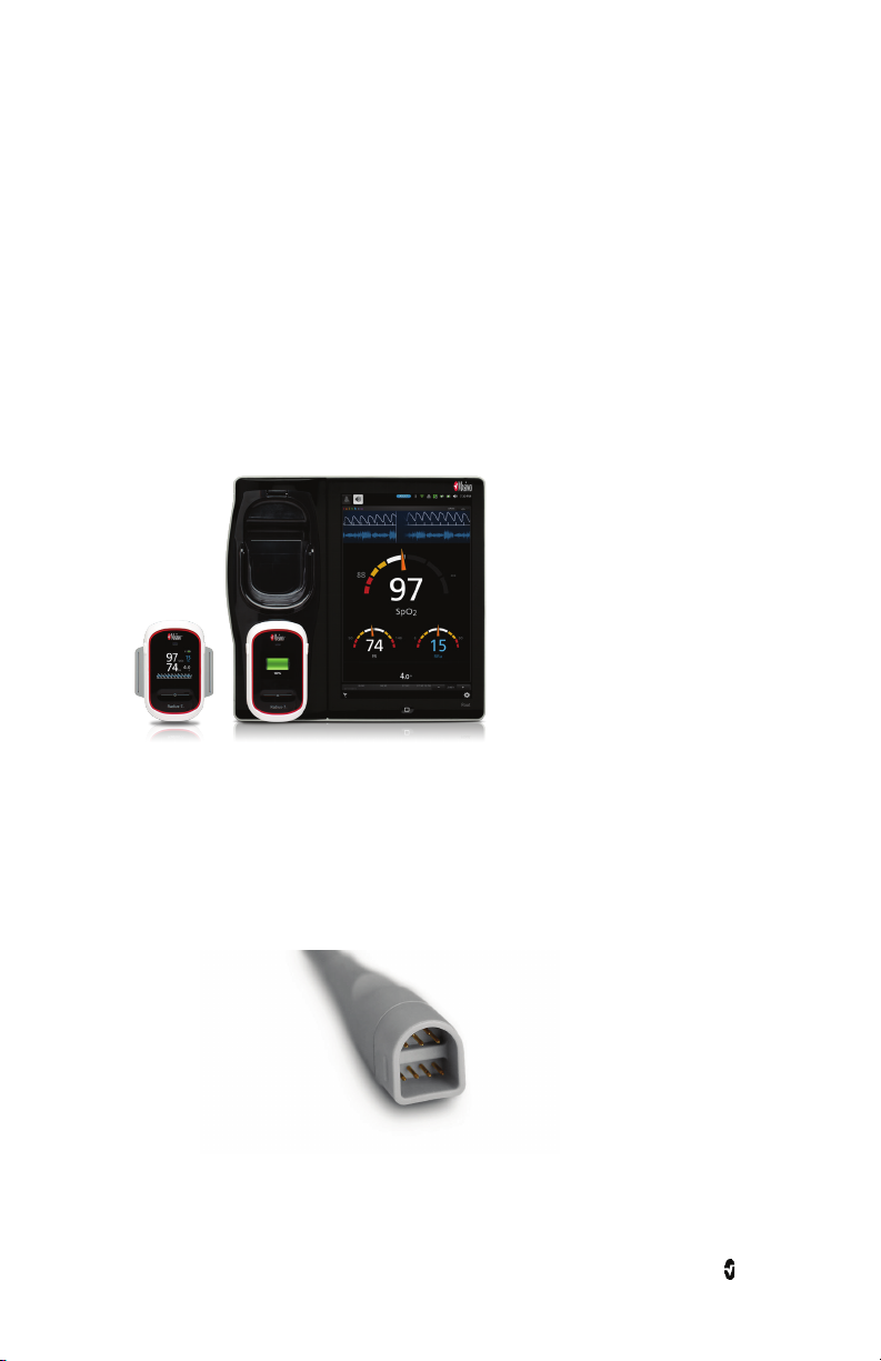
Root® is a patient monitoring and connectivity platform. It offers multiple high-impact
innovations for broad applications across the continuum of care.
• Instantly interpretable, high-visibility display of Masimo’s breakthrough SET
• Intuitive, touchscreen navigation for easy and adaptable use in any hospital
• Flexible measurement expansion through Masimo Open Connect (MOC-9™).
• Designed for third-party measurement expansion to allow other companies to add
• Built-in network connectivity gateway through Iris™ for standalone devices such as
• Docking and charging station for Radical-7
• Ability to display data on a secondary display.
For all prescribing information and instructions for use of the compatible medical devices
that are connected to Root, see Operator’s Manual or Instructions for Use for the specific
medical device.
®
SET measurements.
rainbow
environment.
to the platform measurements.
IV pumps, ventilators, beds, and other patient monitors.
®
and Radius-7® Battery Module.
®
and
Intended Use
The Masimo Root Monitoring System is indicated for use by healthcare professionals for the
monitoring of multiple physiological parameters in healthcare environments.
The Masimo Root Monitoring System can transmit data for supplemental remote viewing and
alarming (e.g., at a central station).
The Masimo Root Monitoring System can be used with the optional Radical-7, ISA product
family, Radius-7, and/or the SedLine module.
The Masimo Root Monitoring System is intended to be used with connected measurement
modules compatible with Root interfaces.
Indications for Use
The Masimo Root Monitoring System is indicated for use by healthcare professionals for the
monitoring of multiple physiological parameters in healthcare environments.
The Masimo Root Monitoring System can transmit data for supplemental remote viewing and
alarming (e.g., at a central station).
The optional Masimo Radical-7 Pulse CO-Oximeter and Accessories are indicated for the
continuous noninvasive monitoring of functional oxygen saturation of arterial hemoglobin
), pulse rate, carboxyhemoglobin saturation (SpCO), methemoglobin saturation
(SpO
2
(SpMet), total hemoglobin concentration (SpHb), and/or respiratory rate (RRa). The Masimo
www.masimo.com 9 Masimo
Page 12

Root Product Description and Features, Intended Use and Indications for Use
Radical-7 Pulse CO-Oximeter and accessories are indicated for use with adult, pediatric, and
neonatal patients during both no motion and motion conditions, and for patients who are
well or poorly perfused in hospitals, hospital-type facilities, mobile, and home environments.
In addition, the Masimo Radical-7 Pulse CO-Oximeter and accessories are indicated to provide
the continuous noninvasive monitoring data obtained from the Masimo Radical-7 Pulse
CO-Oximeter and accessories of functional oxygen saturation of arterial hemoglobin (SpO
and pulse rate to multi-parameter devices for the display of those devices.
)
2
The optional Masimo Radius-7 Wearable Pulse CO-Oximeter and Accessories are indicated for
the continuous noninvasive monitoring of functional oxygen saturation of arterial
hemoglobin (SpO
saturation (SpMet), total hemoglobin concentration (SpHb), and/or respiratory rate (RRa).
), pulse rate, carboxyhemoglobin saturation (SpCO), methemoglobin
2
The Masimo Radius-7 Wearable Pulse CO-Oximeter and accessories are indicated for use with
adult and pediatric patients during both no motion and motion conditions, and for patients
who are well or poorly perfused in hospitals and hospital-type facilities.
The optional ISA product family consists of three types of sidestream gas analyzers (ISA CO
ISA AX+ and ISA OR+), intended to be connected to other medical backboard devices for
monitoring of breath rate and the following breathing gases:
ISA CO2: CO2
ISA AX+: CO
, N2O, Halothane, Isoflurane, Enflurane, Sevoflurane and Desflurane
2
ISA OR+: CO2, O2, N2O, Halothane, Isoflurane, Enflurane, Sevoflurane and Desflurane
ISA CO
, ISA AX+ and ISA OR+ are intended to be connected to a patient breathing circuit for
2
monitoring of inspired/expired gases during anesthesia, recovery and respiratory care. The
intended environment is the operating suite, intensive care unit and patient room. ISA CO2 is
also intended to be used in road ambulances. The intended patient population is adult,
pediatric and infant patients.
The optional SEDLine Sedation Monitor is indicated for use in the operating room (OR),
intensive care unit (ICU), and clinical research laboratory. It is intended to monitor the state
of the brain by real-time data acquisition and processing of EEG signals. The system includes
the Patient State Index (PSi), a proprietary computed EEG variable that is related to the effect
of anesthetic agents
,
2
Contraindication
None.
www.masimo.com 10 Masimo
Page 13

Safety Information, Warnings, and Cautions
CAUTION: Root is to be operated by, or under the supervision of, qualified personnel only. The
manual, accessories, directions for use, all precautionary information, and specifications
should be read before use. Refer to Operator's Manuals for ISA, Kite, Patient SafetyNet,
Radical-7, Radius-7, and SedLine for additional safety information, warnings, and cautions.
Safety Warnings and Cautions
WARNING: Do not use Root if it appears or is suspected to be damaged.
WARNING: Do not adjust, repair, open, disassemble or modify Root. Injury to personnel or
equipment damage could occur. Return Root for servicing.
WARNING: Do not use Root during or nearby magnetic resonance imaging (MRI) or in an MRI
environment.
WARNING: Do not place Root or accessories in any position that might cause it to fall on the
patient.
WARNING: To ensure safety, avoid stacking multiple devices or placing anything on the
device during operation.
WARNING: Do not use Root in the presence of flammable anesthetics or other flammable
substance in combination with air, oxygen-enriched environments or nitrous oxide to avoid
risk of explosion.
WARNING: To reduce the risk of explosion, only replace battery with Masimo supplied parts.
WARNING: Do not start or operate the Root unless the setup was verified to be correct.
WARNING: To ensure safety, only use Masimo authorized devices with Root.
WARNING: To protect against fire hazard, replace only with recommended fuses of the same
type, current rating, and voltage rating.
WARNING: Do not remove the back panel of the device. This could cause injury to personnel
or device damage.
WARNING: Electrical Shock Hazard: To protect against injury, follow the directions below:
• Avoid placing the device on surfaces with visible liquid spills.
• Do not soak or immerse the device in liquids.
• Do not attempt to sterilize the device.
• Use cleaning solutions only as instructed in this Operator's Manual.
• Do not attempt to clean the Root while monitoring patient.
WARNING: Do not plug in or remove the power cord with wet hands to avoid risk of electric
shock. Ensure that your hands are clean and dry before touching the power cord.
WARNING: When positioned on a flat surface, the device should be secured with a mounting
system recommended by Masimo.
WARNING: As with all medical equipment, carefully route patient cables to reduce the
possibility of patient entanglement or strangulation.
www.masimo.com 11 Masimo
Page 14

Root Safety Information, Warnings, and Cautions
CAUTION: Do not place the Root where the controls can be changed by the patient.
CAUTION: To ensure patient isolation, connect only Masimo devices that have been designed
for Root.
CAUTION: Equipment intended to be connected to signal input/signal output ports should
comply with applicable electrical safety standards to further minimize the risk of electric
shock. Only devices that have been configured to operate with Root may function properly
when connected.
CAUTION: Only use the AC power cable provided by Masimo. Using a different AC power cable
could cause damage to Root. Check the power cord and plug to ensure that it is intact and
undamaged.
CAUTION: To avoid risk of electrical shock, this equipment must only be connected to a
supply mains with a protective earth connection. Do not under any circumstances remove the
grounding conductor from the power plug.
CAUTION: Use a grounded outlet for proper equipment grounding. A hospital-grade outlet is
required.
CAUTION: Do not place Root where the appliance inlet or the AC power plug cannot be
readily disconnected.
Note: Disconnect the device from AC mains by removing the AC power cord connector from
the device inlet.
Note: If there is any doubt about the integrity of the protective earth conductor arrangement,
operate Root on internal battery power until the AC power supply protective conductor is fully
functional.
Note: Do not monitor more than a single patient at a time on Root.
Note: It is recommended that Root is attached to an AC power source when it is not in use to
ensure that the battery remains fully charged.
Note: For medical technologies that require AC power, the battery should be adequately
charged to ensure backup power in case of AC power disruption.
Performance Warnings and Cautions
WARNING: Root should not be used as the sole basis for medical decisions. It must be used in
conjunction with clinical signs and symptoms.
WARNING: Root may be used during defibrillation. This may affect the accuracy or
availability of the parameters and measurements.
WARNING: Root may be used during electrocautery. This may affect the accuracy or
availability of the parameters and measurements.
WARNING: Wireless communication of alarms to a secondary monitoring station should not
be relied upon as a primary alarm.
WARNING: Do not place the Root against a surface that may cause the alarm to be muffled.
WARNING: Radical-7 may not fully charge in a high ambient temperature environment.
WARNING: Always ensure settings including alarms are appropriate for each patient prior to
use.
www.masimo.com 12 Masimo
Page 15

Root Safety Information, Warnings, and Cautions
WARNING: When using multiple devices in the same or similar environment, use of the same
patient profile (including the same alarm presets) to avoid confusion that can lead to patient
harm.
CAUTION: Ensure the speaker is not covered.
CAUTION: Before using Root under high intensity surgical lights, confirm that the display
settings allow for clear display of measurements.
CAUTION: Do not connect to an electrical outlet controlled by a wall switch or dimmer.
CAUTION: Do not place the Root on electrical equipment that may affect the device,
preventing it from working properly.
CAUTION: Failure to charge Root promptly after a Low Battery alarm may result in the device
shutting down.
CAUTION: To minimize radio interference, other electrical equipment that emits radio
frequency transmissions should not be in close proximity to Root.
CAUTION: If the Radical-7 or Radius-7 stops communicating with Root, parameters and
measurements will not show on the Root; however, this will not affect Radical-7's or
Radius-7's ability to monitor the patient.
CAUTION: In order to establish and maintain Root’s minimum Quality of Service, the
following network specifications should be met before and after installation:
• Wired Network Connection
During Ping Test, passing result if:
a. At least 98% of packets have latency ≤ 30 milliseconds, and
b. No more than 2 % packets loss.
• Wireless Network Connection
During Ping Test, passing result if:
a. At least 98% of packets have latency ≤ 100 milliseconds,
b. No more than 2 % packets loss, and
c. Primary access point signal strength at least -67 dBm.
CAUTION: The wireless quality of services may be influenced by the presence of other devices
that may create radio frequency interference (RFI). Some RFI devices to consider are as
follows: electrocautery equipment, cellular telephones, wireless PC and tablets, pagers, RFID,
MRI electrically powered wheelchair, etc. When used in the presence of potential RFI devices,
consideration should be taken to maximize separation distances and to observe for any
potential signs of interference such as loss of communication or reduced Wi-Fi signal
strength.
Note: Root is provided with a Wi-Fi signal indicator as an indication of Wi-Fi communication.
Note: Root’s alarm capabilities have been designed to be independent of the Wi-Fi
communication feature in order to preserve Root’s primary alarms.
www.masimo.com 13 Masimo
Page 16

Root Safety Information, Warnings, and Cautions
Kite
WARNING: When using Root the Kite accessory does not generate or manage alarms. The
Root alarms, used in conjunction with clinical signs and symptoms, are the primary sources
for determining that an alarm condition exists.
CAUTION: Kite is not a primary display. Medical decisions should be made using data from
the primary display of a device in conjunction with clinical signs and symptoms.
Patient SafetyNet System
Note: The wireless communication status between Root and Patient SafetyNet is displayed
by Patient SafetyNet.
Cleaning and Service Warnings and Cautions
WARNING: Electrical Shock Hazard: The Root battery should be installed and/or removed
from Root only by qualified personnel.
WARNING: Do not use petroleum-based or acetone solutions, or other harsh solvents, to
clean the Root. These substances affect the device’s materials and device failure can result.
CAUTION: Do not touch, press, or rub the display panels with abrasive cleaning compounds,
instruments, brushes, rough-surface materials, or bring them into contact with anything that
could scratch the display.
CAUTION: Do not submerge the Root in any cleaning solution or attempt to sterilize by
autoclave, irradiation, steam, gas, ethylene oxide or any other method. This will seriously
damage the device.
CAUTION: Electrical shock and flammability hazard: Before cleaning, always turn off the
device and disconnect from any AC power source.
CAUTION: An operator may only perform maintenance procedures specifically described in
the manual. Refer servicing to qualified service personnel trained in the repair of this
equipment.
CAUTION: Electrical Shock Hazard: Carry out periodic tests to verify that leakage currents of
patient-applied circuits and the system are within acceptable limits as specified by the
applicable safety standards. The summation of leakage currents must be checked and in
compliance with IEC 60601-1 and UL60601-1. The system leakage current must be checked
when connecting external equipment to the system. When an event such as a component
drop of approximately 1 meter or greater or a spillage of blood or other liquids occurs, retest
before further use. Injury to personnel could occur.
Note: Excessive cleaning solution can flow into the device and cause damage to internal
components.
Compliance Warnings and Cautions
WARNING: Changes or modifications not expressly approved by Masimo shall void the
warranty for this equipment and could void the user’s authority to operate the equipment.
WARNING: Do not incinerate the battery.
www.masimo.com 14 Masimo
Page 17

Root Safety Information, Warnings, and Cautions
WARNING: In accordance with international telecommunication requirements, the frequency
band of 2.4 GHz and 5.15 to 5.25 GHz is only for indoor usage to reduce potential for harmful
interference to co-channel mobile satellite systems.
CAUTION: Consideration to the compliance of the IEC 60601-1-1 standard should be made
when configuring Root as part of a Medical System.
CAUTION: Disposal of Product: Comply with local laws in the disposal of the device and/or its
accessories.
Note: Use Root in accordance with the Environmental Specifications section in the
Operator's Manual.
Note: This device complies with Part 15 of the FCC Rules. Operation is subject to the
following two conditions: (1) This device may not cause harmful interference, and (2) this
device must accept any interference received, including interference that may cause
undesired operation.
Note: This equipment has been tested and found to comply with the limits for a Class A
digital device, pursuant to part 15 of the FCC Rules. These limits are designed to provide
reasonable protection against harmful interference when the equipment is operated in a
commercial environment. This equipment generates, uses and can radiate radio frequency
energy and, if not installed and used in accordance with the instruction manual, may cause
harmful interference to radio communications. Operation of this equipment in a residential
area is likely to cause harmful interference in which case the user will be required to correct
the interference at his own expense.
In order to maintain compliance with FCC regulations, shielded cables must be used with this
equipment. Operation with non-approved equipment or unshielded cables is likely to result in
interference to radio and TV reception. If this equipment does cause harmful interference to
radio or television, which can be determined by turning the equipment off and on, the user is
encouraged to try to correct the interference by one or more of the following measures:
• Reorient or relocate the receiving antenna.
• Increase the separation between the equipment and receiver.
• Connect the equipment into an outlet on a circuit different from that to which the
receiver is connected.
• Consult the dealer or an experienced radio/TV technician for help.
Note: To satisfy RF exposure requirements, this device and its antenna must operate with a
separation distance of at least 20 cm from all persons and must not be co-located or
operating in conjunction with any other antenna or transmitter.
Note: This equipment has been tested and found to comply with the Class A limits for
medical devices according to the EN 60601-1-2: 2007, Medical Device Directive 93/42/EEC.
These limits are designed to provide reasonable protection against harmful interference in a
hospital environment.
Note: This Class A digital apparatus complies with Canadian ICES-003.
Note: Root is not intended for use during patient transport outside the healthcare facility.
www.masimo.com 15 Masimo
Page 18

Page 19
Chapter 1: Description
Root can be used in the following ways:
• As a docking station and charger for Radical-7 and Radius-7 Battery Module.
• As a bedside monitoring display for parameters on Radical-7, Radius-7, and MOC-9
modules.
• As a connectivity gateway for standalone devices.
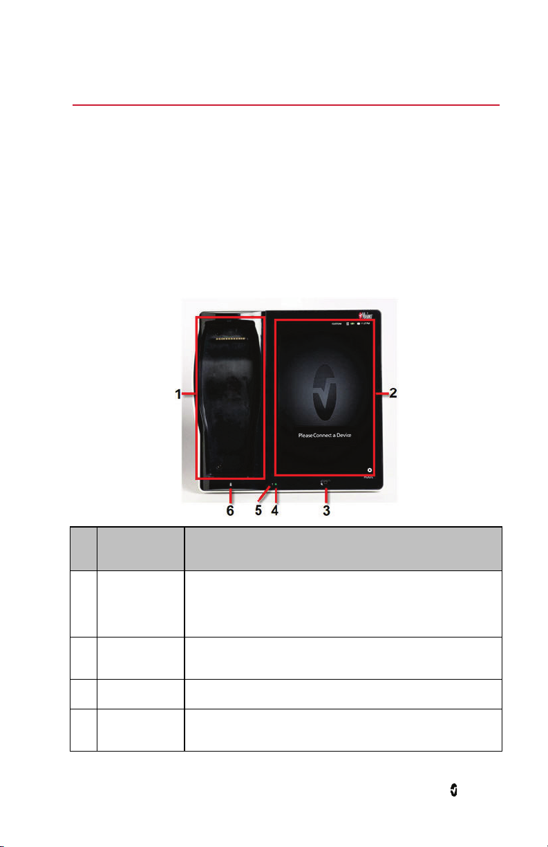
Features
Front View
Ref. Feature Description
Provides a docking station for the Radical-7 and Radius-7 (Note:
1 Docking Station
Root Display and
2
Touchscreen
3 Home Button Provides access to the Main Screen.
Root Charging
4
Indicator
www.masimo.com 17 Masimo
Battery Charging Adapter required for Radius-7). While docked, the
Radical-7 can communicate monitored parameters and
measurements.*
Provides a frontal display and interface for user interactions.
Shows an indication of the battery charge for Root.
Page 20
Root Chapter 1: Description
Ref. Feature Description
AC Power
5
Indicator
Shows an indication of AC power connection Root.
6
Radical-7
Charging
Indicator
Shows an indication of battery charge for the Radical-7 in the
Docking Station.
*Only the touchscreen version of the Radical-7 is able to communicate monitored parameters
and measurements. All other versions can only charge in the docking station but not
communicate with Root.
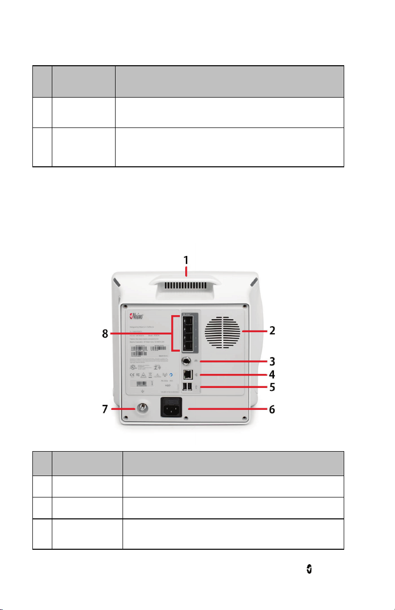
Back View
Ref. Feature Description
1 Handle Allows the user to transport Root.
2 Speaker Provides audible notification.
Nurse Call
3
Connector
Provides a connection to a Nurse Call system.
www.masimo.com 18 Masimo
Page 21
Root Chapter 1: Description
Ref. Feature Description
4 Ethernet Port Provides a network connection to Root using an RJ-45 cable.
5 USB Ports (2) Provide USB 2.0 connectivity.
Power Entry
6
Module
Equipotential
7
Ground Connector
Iris Connectivity
8
Ports (4)
Contains the input connector for a hospital grade AC power cord
and the fuse holder.
Provides optional functional earthing for Root to eliminate
potential differences. The use of the Equipotential Ground
Connector should be in accordance with IEC 60601-1.
Provide connection for standalone devices.
www.masimo.com 19 Masimo
Page 22
Root Chapter 1: Description
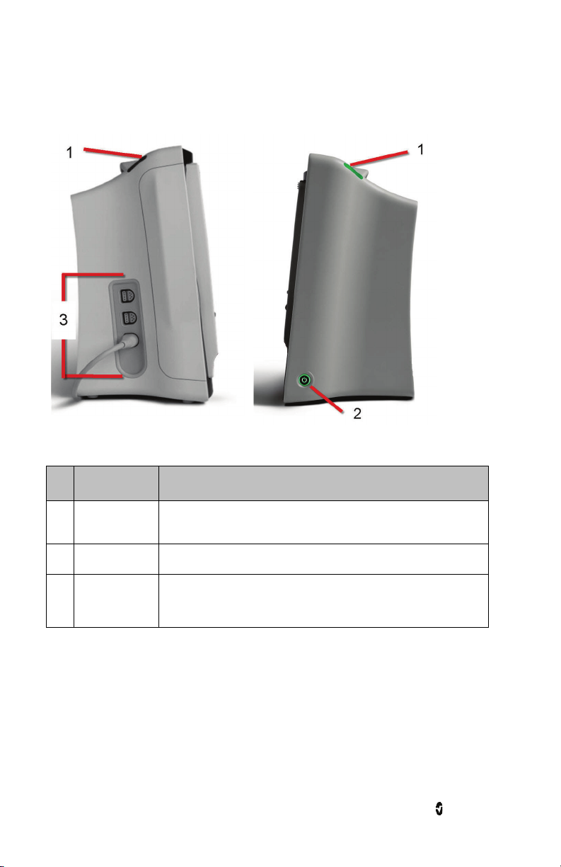
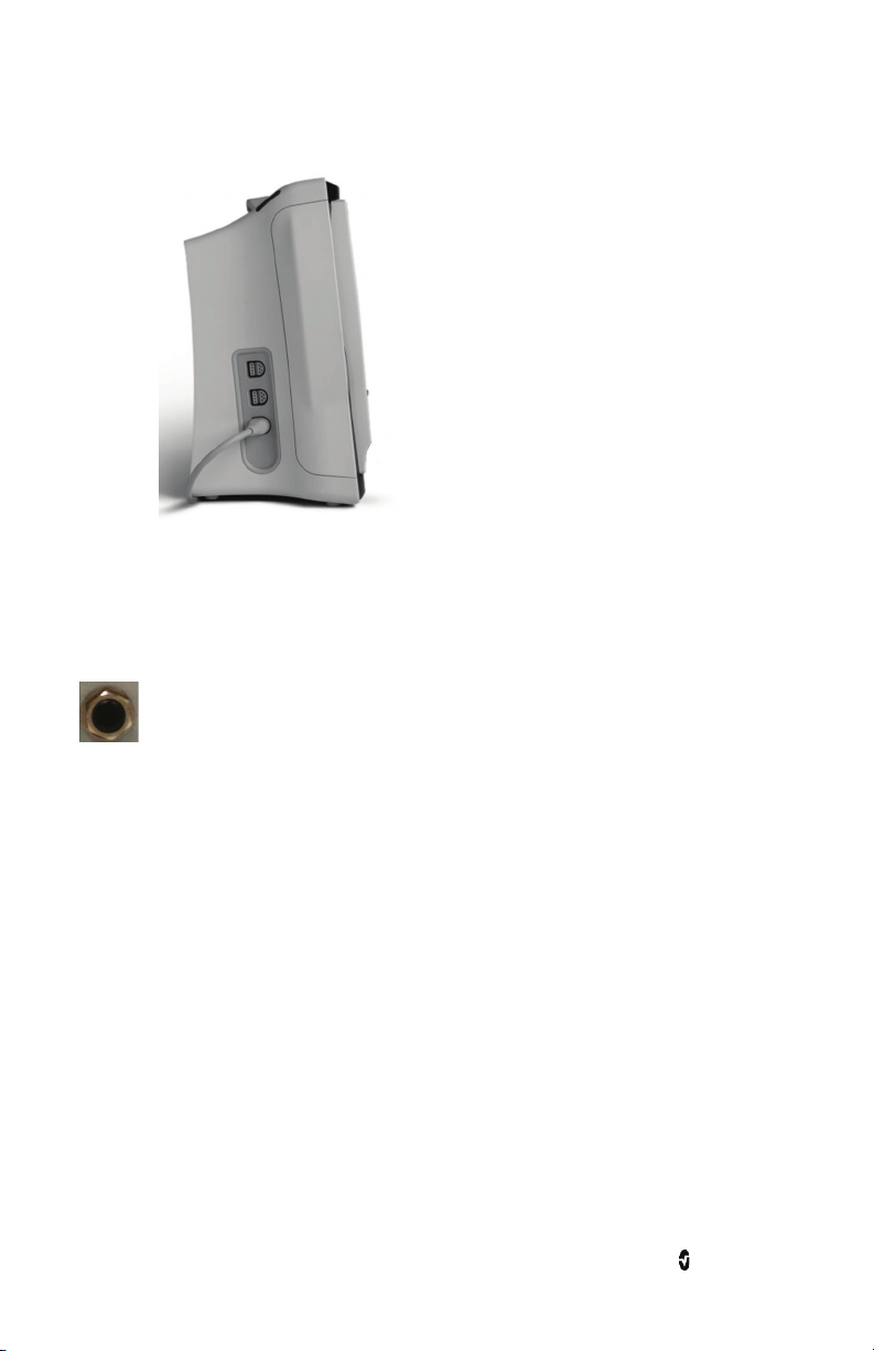
Side Views
Left Side Right Side
Ref. Feature Description
System Status
1
Lights
Provides an indication of system messages and alarm priority. See
System Status Lights on page 67.
2 Power Button Places Root in Power On, Sleep and Power Off modes.
3 MOC-9 Ports (3) Provide connectivity for MOC-9 modules.
www.masimo.com 20 Masimo
Page 23

Chapter 2: Setting Up
Unpacking and Inspection
To unpack and inspect Root
1. Remove Root from the shipping carton and examine it for signs of shipping
damage or exposed electronics.
2. Confirm that you have all components for the Root by checking all materials
against the packing list:
• Root
• AC power cord
Note: Save all packing materials, invoice and bill of lading. These may be required
to process a claim with the carrier.
If anything is missing or damaged, contact Masimo's Technical Service Department. See
Return Procedure on page 105.
Guidelines for Setting Up
Root has a built-in bracket interface that allows it to be mounted on a pole or roll stand.
When setting up Root, follow these guidelines:
• Place on a stable, hard, flat, and dry surface near the patient.
• Maintain a minimum of three (3) centimeters (one [1] inch) of free space around
Root.
• Ensure that the back panel speaker is not covered to avoid a muffled alarm sound.
• Charge Root's battery fully before use. See Initial Battery Charging on page 23.
Root should not be operated outside the environmental conditions listed in the
specifications section. See Environmental on page 92.
www.masimo.com 21 Masimo
Page 24
Root Chapter 2: Setting Up
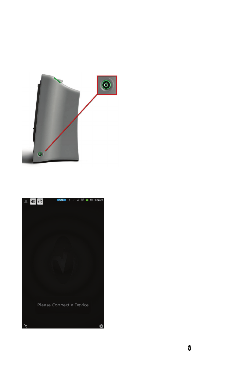
Power On
The Power Button can be used for Power On, Sleep, and Power Off. To Power On, press the
Power Button for two (2) seconds until a single audible tone sounds.
Once Root turns on, if no Radical-7, Radius-7, or MOC-9 module is connected, the Root display
shows the following message: Please Connect a Device. The user is now able to connect
Radical-7, Radius-7, and MOC-9 module.
For information about Sleep Mode and Power Off, see Sleep and Power Off on page 69.
www.masimo.com 22 Masimo
Page 25
Root Chapter 2: Setting Up
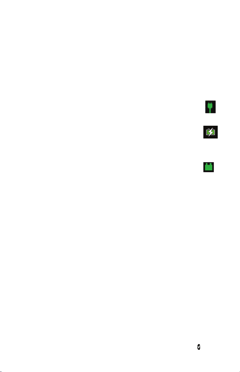
Initial Battery Charging
To charge the battery for the first time
1. Securely plug the AC power cord into power entry module.
2. Plug the hospital grade AC power cord into an AC power source.
3. Verify that Root's battery is charging by ensuring that the AC Power Indicator (1)
is green and the Battery icon on the Status Bar (2) is solid green or has the
charging symbol. See AC Power Indicator on page 68 and About the Status Bar
on page 28.
(1)
(2)
4. The Root Charging Indicator remains orange while the battery is charging and
will illuminate green
and About the Status Bar on page 28.
when Root is fully charged. See Root Battery on page 52
See Safety Information, Warnings, and Cautions on page 11.
www.masimo.com 23 Masimo
Page 26
Root Chapter 2: Setting Up
Radical-7 Connection
It is recommended that Root be powered on before performing the steps below.
1. Snap the Radical-7 into the Docking Station.
2. If the Radical-7 is not yet turned on, press the power button on the Radical-7 to
power it on.
3. When properly connected, the Radical-7 Charging Indicator light will illuminate.
An illuminated Radical-7 Battery icon will also appear in the Status Bar. See About
the Status Bar on page 28
4. Root display will show active measurements and parameters.
For Radical-7 charging conditions, see Radical-7 and Radius-7 Charging Indicator on page 68.
www.masimo.com 24 Masimo
Page 27
Root Chapter 2: Setting Up
Radius-7 Connection
It is recommended that Root be powered on before performing the steps below.
1. Ensure the Radius-7 Battery Charging Adapter is properly docked in the Docking
Station area of Root.
2. Activate the Bluetooth radio on Root. (for more information see Operator’s Manual
for Radius-7).
3. Place the Radius-7 Battery Module into the charging area of the Radius-7 Battery
Charging Adapter.
4. Root will emit a tone when pairing has completed (see Operator's Manual for
Radius-7 for more information).
5. When properly connected, an illuminated Radius-7 Battery icon will appear in the
Status Bar, and the rainbow Window will appear on the Root display.
MOC-9 Connection
To connect a MOC-9 module to Root
1. Identify the Masimo Open Connect (MOC-9 TM) end of the module.
www.masimo.com 25 Masimo
Page 28
Root Chapter 2: Setting Up
2. Insert the MOC-9 end of the module securely into a MOC-9 port on Root.
See Chapter 6: MOC-9 on page 81
Nurse Call Connection
Use a Nurse Call connection cable to connect to a Nurse Call System.
To connect to a Nurse Call System
1. Identify the Nurse Call connection end (1/4 inch round female connector) of the
cable.
2. Insert the Nurse Call connection cable securely into the compatible port on Root.
3. Depending on the connection type of the Nurse Call System, it may be necessary to
orient the other end of the Nurse Call connection cable to fit correctly into the
system connection.
4. For more information, see Device Settings on page 48.
www.masimo.com 26 Masimo
Page 29
Chapter 3: Operation
The information in this chapter assumes that Root is set up and ready for use. This chapter
provides necessary information for proper operation of the device. Do not operate Root
without completely reading and understanding these instructions.
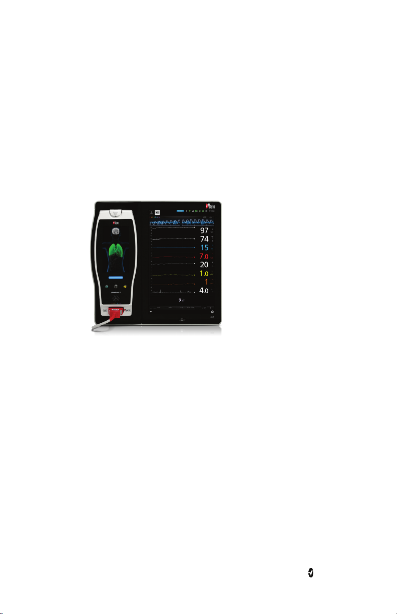
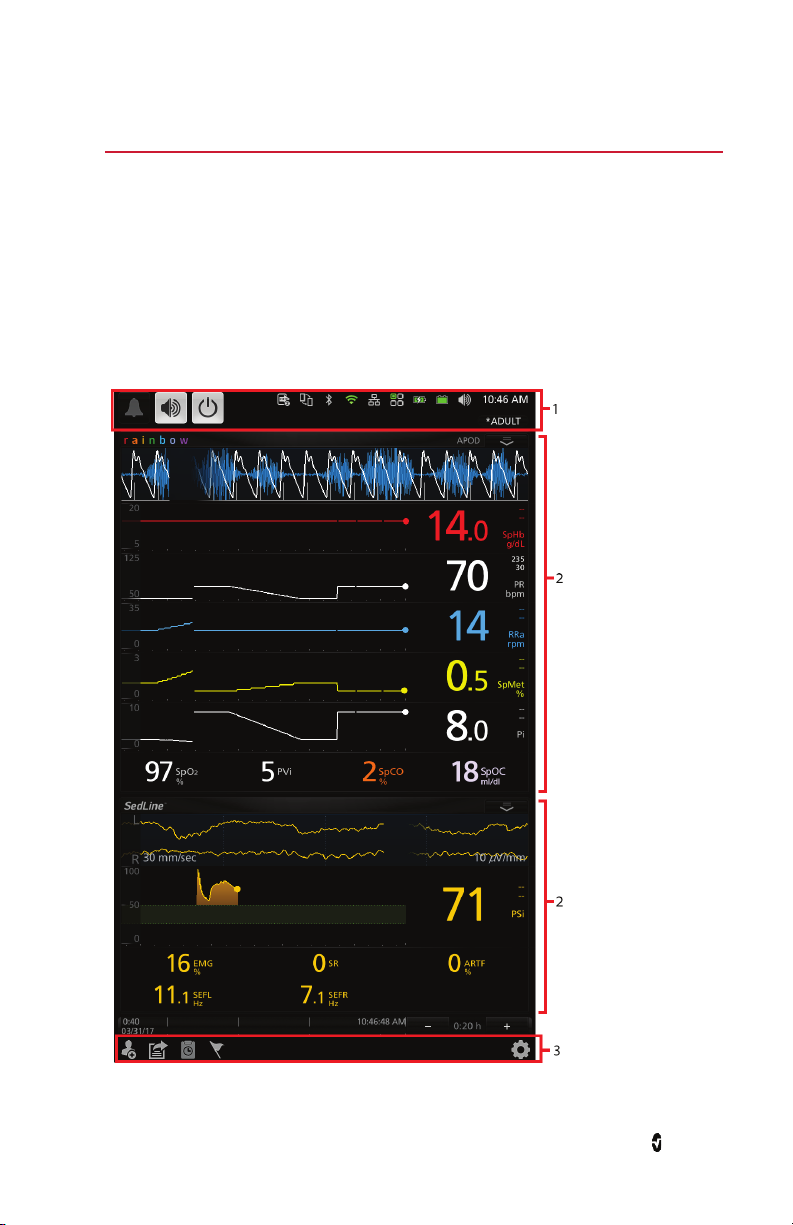
About the Main Screen
The Main Screen consists of several features. The following shows the Main Screen when two
different devices are connected: Radical-7 (top) showing rainbow
measurements and SedLine module (bottom) showing brain function measurements.
®
parameters and
www.masimo.com 27 Masimo
Page 30
Root Chapter 3: Operation
Ref. Feature Description
Status
1
Bar
2 Windows
Action
3
Bar
Displays system status as well as icons that provide shortcuts to menu
items or actions. See About the Status Bar on page 28.
Provides a dynamic, user-configurable display area for all the data from
connected medical devices.
Provides icons for access to Root options for Patient Admit, EMR Push,
Session Management, Manual Events and the Main Menu. See Accessing
Main Menu Options on page 43.
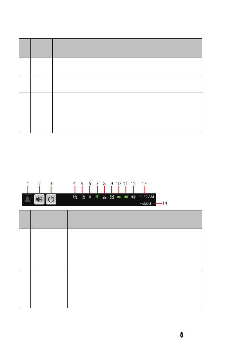
About the Status Bar
At the top of the Main Screen is the Status Bar with interactive icons. Each icon provides a
shortcut to a menu item or an action on Root. An example is shown below.
Ref. Feature Description
Displays alarm status and temporarily mutes all audible alarms for
1 Alarm Silence
Root, Radical-7, Radius-7, and MOC-9 modules.
See Alarm Silence on page 62.
Displays Audio Pause status and temporarily silences an alarm
2 Audio Pause
event.
See Audio Pause on page 62.
www.masimo.com 28 Masimo
Page 31

Root Chapter 3: Operation
Ref. Feature Description
Allows for patient monitoring to be temporarily suspended.
3 Standby Mode
4 IntelliBridge
5 Kite
6 Bluetooth
7 Wi-Fi
Available when using Root with Radical-7 or Radius-7.
See Standby Mode on page 64.
Provides access to the Device Output screen for activation or
deactivation of IntelliBridge connection. If this icon is visible, then
IntelliBridge connectivity has been enabled.
See Device Settings on page 48
Provides access to the Kite screen for activation or deactivation of
Kite connection. If this icon is visible, then Kite connectivity has
been enabled.
See Kite on page 49
Provides access to the Bluetooth screen. If this icon is visible, then
Bluetooth connectivity has been enabled.
See Bluetooth on page 51.
Provides access to the Wi-Fi screen. If this icon is visible, then Wi-Fi
connectivity has been enabled. The icon itself also indicates the
strength of the wireless signal.
See Wi-Fi on page 50.
Provides access to the Ethernet screen. If this icon is visible, then
8 Ethernet
www.masimo.com 29 Masimo
Ethernet connectivity has been enabled.
See Ethernet on page 51.
Page 32

Root Chapter 3: Operation
Ref. Feature Description
Provides access to the Iris screen. The example shown above
indicates that standalone devices are connected to Ports 1, 2, and 3
and the information is being sent to Patient SafetyNet or
9 Iris
Connectivity Gateway.
The color of the icon matches the status colors of connected
standalone devices on the Iris screen. See Chapter 7: Iris on page
83.
Displays charging status for Radical-7 or Radius-7 and provides
Radical-7 or
10
Radius-7 Battery
access to the Battery Radical-7 screen. The example shows that the
battery is currently charging.
See Radical-7 and Radius-7 Charging Indicator on page 68.
Displays charging status for Root and provides access to the Battery
11 Root Battery
Root screen. The example shows that the battery is currently
charging.
See Root Charging Indicator on page 68.
Provides access to the Sounds screen to adjust alarm and pulse tone
12 Sounds
volume. This icon does not indicate the actual volume level of the
alarm and pulse tone.
See Sounds on page 47.
Displays the current time and provides access to the Localization
13 Current Time
screen which contains settings related to local time, language and
geography.
See Localization on page 49.
Provides access to the Profiles screen. The example shown
14 Profiles
illustrates that Profiles is currently set to Adult for an adult patient.
See Profiles on page 59.
www.masimo.com 30 Masimo
Page 33

Root Chapter 3: Operation
About the Action Bar
At the bottom of the Main Screen is the Action Bar with interactive icons. Each icon provides
a shortcut to a menu item or an action on Root. An example is shown below.
Ref. Feature Description
1 Patient Admit Info
Provides Access for input of patient info either by importing or
manual entry.
2 EMR Push Provides Access to Manual Entry of EMR Push information.
3
Session
Management
Provides Access to Session Management. See Session
Management on page 65.
4 Manual Events Provides access for manual event markers.
Provides access to the configuration options for Root and
5 Main Menu
connected medical devices.
See Accessing Main Menu Options on page 43.
www.masimo.com 31 Masimo
Page 34
Root Chapter 3: Operation
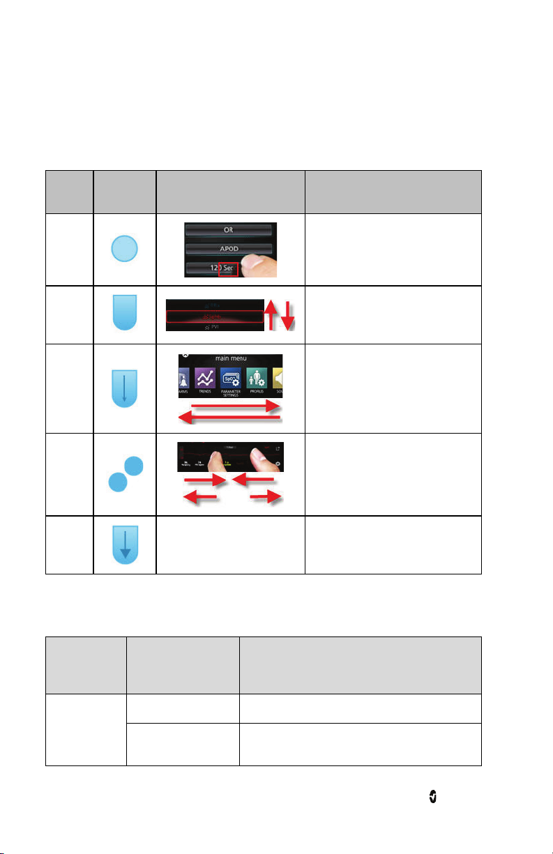
Using the Touchscreen Interface
Using the gestures described below, the user is able to customize the viewing experience,
including displaying the highest priority parameters and measurements. The availability of
navigation features is dependent on the connected medical devices.
Action Illustration Example Description
Press
Slide
Swipe
Pinch
Drag
and
Drop
Below is a list of all the different types of controls available on Root and the various ways to
interact with each type of control.
See Customizing Windows on
page 41.
Touch and release. Action performed
once finger is released.
Touch, move (left, right, up or down),
and release. Moves an object across
the display.
Touch, move (left, right, up or down),
and release quickly.
Touch, move, and release via two
touch points. Moving touch points
apart zooms in, and moving them
together zooms out.
Touch, hold, drag an object to
desired position, and drop it by
releasing.
Control Applicable Actions Description
Toggle Slide knob Switches between toggle states
Press left or right of
toggle
www.masimo.com 32 Masimo
Quickly moves knob left or right
Page 35

Root Chapter 3: Operation
Control Applicable Actions Description
Labeled Toggle Slide knob Switches between toggle states
Press left or right of
toggle
Press label Quickly moves knob left or right
Spinner Press center (focused)
tile
Swipe up or down When open, scrolls through spinner tiles
Press unfocused tile When open, scrolls tile into center (focused)
Press anywhere
outside spinner
Slider Slide knob Moves knob
Press anywhere along
slider path
Slider Spinner Slide knob Moves knob
Press anywhere along
slider path
Press center (focused)
tile
Quickly moves knob left or right
When closed, expands the spinner
When open, collapses the spinner
position
When open, collapses spinner
Quickly moves knob to Tap position
Quickly moves knob to Tap position
When closed, expands the spinner
When open, collapses the spinner
Swipe up/down When open, scrolls through spinner tiles
Press unfocused tile When open, scrolls tile into center (focused)
Press anywhere
outside spinner
Button Press Performs action (as defined by the button
Icon Menu Press tile Opens menu specified by tile
www.masimo.com 33 Masimo
position
When open, collapses spinner
description)
Page 36

Root Chapter 3: Operation
Control Applicable Actions Description
Swipe left or right
(anywhere)
Press bottom
indicator icon
Window Press parameter or
measurement
Press and hold Enables parameter and measurement drag and
Well Press parameter or
measurement
Press and hold Enables parameter and measurement drag and
Live Waveform Swipe down Separates pleth and acoustic waveforms
Swipe up Combines pleth and acoustic waveforms
Trend Line Pinch in Zooms in
Pinch out Zooms out
Scrolls icons left or right
Quickly centers tile corresponding to indicator icon
When no parameter or measurement alarm is
present, opens parameter or measurement menu
When parameter or measurement alarm is present,
silences parameter or measurement alarm
drop
When no parameter or measurement alarm is
present, opens parameter or measurement menu
When parameter or measurement alarm is present,
silences parameter or measurement alarm
drop
Pan Changes time range
Press y-axis Opens parameter or measurement trend menu
Trend Zoom Press '+' Increases time range
Press '-' Decreases time range
Press time label Resets time range to default
Alarm Silence
icon
www.masimo.com 34 Masimo
Press Silences all alarms
Page 37

Root Chapter 3: Operation
Control Applicable Actions Description
Audio Pause
Press Enables Audio Pause
icon
Other Status
Press Opens relevant menu
Bar icons
Back Arrow Press Exits menu, abandons any changes
Menu Navigation
When navigating through menus and configuring settings, all changes must be confirmed by
selecting OK. To cancel the changes, select Cancel. Any screen requiring selection of
option(s) will time out after one (1) minute of inactivity and return to the Main Screen.
To navigate to the previous screen, press the arrow at the top left corner of the touchscreen.
To return to the Main Screen, at any time, press the Home Button at any time. The Home
Button is always illuminated when Root is powered on.
www.masimo.com 35 Masimo
Page 38

Root Chapter 3: Operation
Understanding Windows
Root creates a Window for Radical-7, Radius-7, and compatible medical devices that are
connected to Root. Parameters or measurements can be expanded or minimized within a
Window to customize view. Radical-7 Windows are shown in the examples below.
Windows provide waveforms along with either a Trend View or an Analog View. Trend View
displays each parameter or measurement alongside a graph of its values over time. Analog
View displays values in relation to alarm ranges.
Details about the displayed information of parameters and measurements can be found in
the directions for use or Operator's Manual of Radical-7, Radius-7, and MOC-9 modules.
Trend View
Analog View
www.masimo.com 36 Masimo
Page 39

Root Chapter 3: Operation
Ref. Feature Description
1 Window
Action
2
Menu
3 Waveform
Trend
4a
Display
Analog
4b
Gauge
5 Well
The area where all data from a docked Radical-7, Radius-7, or connected
MOC-9 module are displayed.
This menu allows the user to change between Trend View and Analog
View. For NIBP and Temperature, the action menu allows access to
additional settings. Sensitivity settings can also be selected through the
action menu.
Shows a parameter or measurement over time (only for Radical-7,
Radius-7, and MOC-9 modules).
(Available only in Trend View) Parameters and measurements are shown
as Trend Displays in Trend View. A parameter or measurement's Trend
Display includes its Value Range, Numeric Value, Alarm Limits and
Parameter label. See Using Trend View on page 38.
(Available only in Analog View) Parameters and measurements are shown
as Analog Gauges in Analog View. A parameter's Analog Gauge includes its
Alarm Limits, Numeric Value, Parameter Label, as well as Alarming,
Caution and Normal Ranges. See Using Analog View on page 39.
Displays parameters and measurements which are not shown as Trend
Displays or Analog Gauges.
www.masimo.com 37 Masimo
Page 40

Root Chapter 3: Operation
Using Trend View
In Trend View, a parameter or measurement is displayed as a graph of its values over time.
The following diagram and table describe key features of a parameter's Trend Display in
Trend View.
Ref. Feature Description
1 Value Range
Press to access the Trend menu where the minimum and
maximum of the range can be modified.
Indicates current viewing of the parameter or measurement.
2 Trend Graph
Displays parameter and measurement over a period of time.
Zoom in and out of a Trend Graph by pinching out and in.
3 Numeric Value Indicates current reading of the parameter or measurement.
4 Alarm Limits
Parameter or
5
Measurement Label
Indicate high and low alarm limits for the parameter or
measurement, if supported.
Indicates the name of the parameter or measurement.
www.masimo.com 38 Masimo
Page 41

Root Chapter 3: Operation
Using Analog View
The Analog View shows parameter and measurement data as a needle pointing to
graduations in a circular array around a dial. This view provides indications of change that
can be interpreted at a quick glance.
Analog View displays alarming and normal ranges of a parameter or measurement. These
indicators can be used to alert clinicians to a patient's condition. To understand specific
parameters or measurements, refer to the directions for use or operator's manuals for
Radical-7, Radius-7, and the appropriate MOC-9 module(s).
The following diagrams and tables describe key features of a parameter's Gauge in Analog
View.
When alarm limits for a specific parameter or measurement are set, the corresponding
Analog gauge re-orients itself.
General features of the Analog View are:
Ref. Feature Description
1 Needle Indicates current status of a parameter or measurement.
2 Alarm Limits
3 Numeric Value
Parameter or Measurement
4
Label
www.masimo.com 39 Masimo
Indicate high and low alarm limits for the parameter or
measurement.
Indicates current reading of the parameter or
measurement.
Indicates the name of the parameter or measurement.
Page 42

Root Chapter 3: Operation
Specific ranges of the Analog View are:
Ref. Feature Color Description
1 Normal Range White
Area of the display range where an alarm will not be
triggered.
2 Caution Range Yellow Area of the display range that provides a caution indicator.
Alarming
3
Range
Red Area of the display range where an alarm will be triggered.
Some ranges display as quarter circles, others display as half circles. A quarter circle displays
when the value has a physiologic normal level at one end of the range. A half circle displays
when the value has a physiologic normal level in the middle of the display range.
In the example below, the SpO
88% will trigger an alarm, and the PR gauge is shown as a half circle, where values below 50
gauge is shown as a quarter circle, where values lower than
2
bpm and above 140 bpm will trigger an alarm.
Quarter Circle Half Circle
www.masimo.com 40 Masimo
Page 43

Root Chapter 3: Operation
Customizing Windows
Windows can be customized by expanding and minimizing parameters and measurements in
both Trend View and Analog View. When a parameter is minimized, it is only displayed in the
Well with its Numeric Value and Parameter Label. When a parameter is expanded, it will be
shown as either a Trend Display or Gauge.
To expand a parameter or measurement
Order Instruction
Step 1 Press and hold the Numeric Value until it dims.
Step 2 Drag the Numeric Value over any Trend Display.
Step 3 Release the Numeric Value.
www.masimo.com 41 Masimo
Page 44

Root Chapter 3: Operation
Minimizing a parameter or measurement
Order Instruction
Step 1 Press and hold the Numeric Value until it shrinks.
Step 2 Drag the Numeric Value to the Well.
Step 3 Release the Numeric Value.
www.masimo.com 42 Masimo
Page 45

Root Chapter 3: Operation
Accessing Main Menu Options
To access the Main Menu options
At the bottom right corner of the touchscreen, press the Main Menu icon.
The Main Menu options are:
Layout
See Layout on page 44.
rainbow
See Rainbow on page 46
Sounds
See Sounds on page 47.
Device Settings
See Device Settings on page 48.
About
See About on page 58.
Trend Settings
See Trend Settings on page 58.
Profiles
See Profiles on page 59.
Iris
See Chapter 7: Iris on page 83.
www.masimo.com 43 Masimo
Page 46

Root Chapter 3: Operation
Layout
Use the Layout screen to select sizing options for Windows and Trend Displays.
Available Layouts
When a Radical-7 or Radius-7 is docked to Root and/or multiple MOC-9 modules are
connected to Root, the user will have the option to select from several pre-configured layouts.
Image below shows layout options available with Radical 7 docked in Root.
Note: Rainbow window can be viewed on a Radical 7, using software V1.5.3.5 or greater, in
several of the pre-configured layouts.
www.masimo.com 44 Masimo
Page 47

Root Chapter 3: Operation
Additional Settings for Layouts
There are different ways to display the parameters and measurements by changing the
Layout Style.
Option Description Factory Default
Trend Style
Analog
Range
The following diagram and tables explain the differences between Fixed and Dynamic modes
for a Trend View.
Controls the sizing of Trend
Displays.
Controls Analog Range
Setting.
Settings
Dynamic Fixed or Dynamic
Fixed Fixed or Dynamic
User Configurable
Settings
www.masimo.com 45 Masimo
Page 48

Root Chapter 3: Operation
Fixed
Ref. Description
1 A set number of Trend Displays can be shown at the same time and all Trend Displays
are fixed in size. Every additional parameter or measurement expanded will replace an
existing Trend Display.
For more information about expanding parameters, see Customizing Windows on page
41.
2 Size of each Trend Display is fixed.
Dynamic
Ref. Description
1 Size of all Trend Displays decreases or increases to accommodate parameter(s)
expanded or minimized. All Trend Displays are always evenly sized.*
For more information about expanding and minimizing parameters, see Customizing
Windows on page 41.
2 *Size of each Trend Display is automatically adjusted.
*When the number of Trend Displays reaches maximum viewing capacity, additional
parameters expanded will result in the replacement of existing Trend Displays.
Rainbow
The rainbow icon is displayed only when a Radical-7 or Radius-7 is docked to Root. See
Operator manuals for Radical-7 or Radius-7.
www.masimo.com 46 Masimo
Page 49

Root Chapter 3: Operation
Sounds
Use the Sounds screen to control the volume level of sounds and duration of audio pause for
Root.
Option Description Factory
Configurable Settings
Default
Setting
Alarm
Volume
Pulse Tone
Volume
Sets the alarm volume level.
Sets the pulse tone volume
level.
Highest
volume
Highest
volume
Slide towards the left to decrease
volume to silence.
Slide towards the left to decrease
volume to silence.
1, 2, 3 minutes, Permanent*,
Permanent with Reminder*.
If Permanent is selected, there will
Audio
Pause
Duration
Sets the length of time that
the audible alarm remains
silenced, when Audio Pause is
enabled. See Audio Pause on
page 62.
2 minutes
be no audible alarms when Audio
Pause is enabled, but visual alarms
will still display.
If Permanent with Reminder is
selected, a tone will sound every
three (3) minutes as a reminder
that Permanent is active when
Audio Pause is enabled.
*Requires the all mute enabled option to be toggled to ON in the Access Control menu. See
Access Control on page 53.
www.masimo.com 47 Masimo
Page 50

Root Chapter 3: Operation
Device Settings
The Device Settings menu allows the user to view and customize settings for Root.
The Device Settings options are:
Localization
See Localization on page 49.
Kite
See Kite on page 49
Wi-Fi
See Wi-Fi on page 50.
Ethernet
See Ethernet on page 51.
Bluetooth
See Bluetooth on page 51.
Root Battery
See Root Battery on page 52.
Radical-7 Battery
See Radical-7 and Radius-7 Battery on page 52.
Brightness
See Brightness on page 53.
Access Control
See Access Control on page 53.
Device Output
See Device Settings on page 48.
www.masimo.com 48 Masimo
Page 51

Root Chapter 3: Operation
Localization
Use the Localization screen to view the current date and time and configure settings related
to local time, language and geography. The user can also access the Localization screen by
pressing the current time on the Status Bar. See About the Status Bar on page 28.
Option Description Factory Default
Configurable Settings
Setting
Language
Date Format
Time Format
Line
Frequency
Selects the language display
for Root.
Sets the display format for
current date.
Sets the display format for
current time.
Sets to match regional power
line frequency.
English
mm/dd/yy
12 hour
60 Hz 50 Hz or 60 Hz
Choose from available
languages.
mm/dd/yy or
dd/mm/yy
12 hour or
24 hour
Date Sets the current date. N/A N/A
Time Sets the current time. N/A N/A
Kite
Use the Kite screen to enable or disable Kite connectivity.
Option Description Factory
Configurable Settings
Default
Setting
Enable Kite
Connection
Activates or deactivates an active
Kite connection.
Off On or Off
www.masimo.com 49 Masimo
Page 52

Root Chapter 3: Operation
Option Description Factory
Configurable Settings
Default
Setting
Pairing Key
Four (4) digit code automatically
assigned for active Kite session.
N/A
Automatic with active
Kite connection
Wi-Fi
The Wi-Fi radio allows for networked communication of data and alarm signals between Root
and a secondary patient monitoring station, Masimo’s Patient SafetyNet over an IEEE 802.11
a/b/g wireless network. The wireless data transmission is an optional network data
transmission to the wired network data transmission, using Root’s integral Ethernet Port.
Root uses only configured MAC addresses to establish wireless communications to prevent
unauthorized connections to other wireless devices. As risk mitigation to the loss of the
wireless communication, Root’s alarm capabilities have been designed to be independent of
the Wi-Fi communication feature in order to preserve Root’s primary alarms.
Use the Wi-Fi screen to enable or disable Wi-Fi connectivity. When Root is connected to a
Wi-Fi network, the Wi-Fi icon on the Status Bar conveys the strength of the connection. See
About the Status Bar on page 28.
Option Description Factory Default
Setting
Configurable Settings
Wi-Fi
Enables or disables Wi-Fi
connectivity.
Off On or Off
Additional fields in the Wi-Fi screen display read-only settings about the Wi-Fi connection
that cannot be configured by the user.
Your Masimo sales representative can provide necessary information regarding an initial
Wi-Fi connection. For more information, see the Patient SafetyNet Operator's Manual.
CAUTION: Unanticipated failure or alteration of network components (including but not
limited to: disconnection or malfunctioning of a networking device/switch/router/ethernet
cable) may result in loss of connectivity of Kite to other hospital systems. Altering or making
changes to the hospital network should be done with proper knowledge.
www.masimo.com 50 Masimo
Page 53

Root Chapter 3: Operation
Ethernet
Use the Ethernet screen to enable or disable Ethernet connectivity. When Ethernet
connectivity is enabled, the Ethernet icon will appear in the Status Bar. See About the Status
Bar on page 28.
Option Description Factory Default
Setting
Ethernet
Enables or disables Ethernet
connectivity.
On On or Off
Configurable
Settings
Additional fields in the Ethernet screen display read-only settings about the Ethernet
connectivity that cannot be configured by the user.
Bluetooth
The Bluetooth radio allows for the detection of the close proximity of Masimo’s MyView
Presence Tag. Root’s detection of Masimo’s MyView Presence Tag is an optional feature that
allows for the display of predetermined customized settings by a clinician. Root utilizes only
configured MAC addresses to establish Bluetooth communication to prevent unauthorized
connection to other Bluetooth enabled devices.
Use the Bluetooth screen to enable or disable Bluetooth connectivity. When Bluetooth
connectivity is enabled, the Bluetooth icon will appear in the Status Bar. See About the
Status Bar on page 28.
Option Description Factory Default
Setting
Bluetooth
Enables or disables Bluetooth
connectivity.
Off On or Off
Configurable
Settings
For more information on how to configure MyView Presence Tag, see the Patient SafetyNet
Operator's Manual.
www.masimo.com 51 Masimo
Page 54

Root Chapter 3: Operation
Root Battery
Use the Root Battery screen to view the specific percentage of charge on the battery. The user
can also access Root's Battery screen by pressing the Battery icon on the Status Bar. See
About the Status Bar on page 28.
Option Description
State of Charge Provides a read-only display of battery level remaining.
Battery Diagnostics Allows trained personnel to access battery diagnostic information.
Radical-7 and Radius-7 Battery
Use the Battery screen to view the specific percentage of charge on the Radical-7 or
Radius-7's battery. For Radical-7, the user can also access the Battery screen by pressing the
Battery icon on the Status Bar. See About the Status Bar on page 28.
Option Description
State of Charge Provides a read-only display of battery level remaining.
Battery Diagnostics Allows trained personnel to access battery diagnostic information.
www.masimo.com 52 Masimo
Page 55

Root Chapter 3: Operation
Brightness
Use the Brightness screen to adjust the brightness of the Root display.
Option Description Factory
Default
Configurable
Settings
Setting
Auto
Brightness
Allows automatic adjustment of Root's
display brightness based on ambient light.
Off On or Off
Adjust the brightness level of the Root
Brightness
display by sliding the button (4 is
4 1, 2, 3, 4
brightest).
Access Control
Access Control contains configurable options and settings that require a password.
To enter Access Control
1. Press the key.
2. When the numeric screen displays, enter the following numbers: 6 2 7 4
Asterisks (****) will be displayed.
To undo an entry, press Backspace.
3. Press Enter to access the password protected screen.
Note: The password will have to be entered every time this screen is accessed.
www.masimo.com 53 Masimo
Page 56

Root Chapter 3: Operation
Option Description Factory
Power On Profile
All Mute
Enabled
Lock Alarm
Volume
Optical Sensor
Off Alarm Delay
Standby
Enabled
Standby
Reminder Tone
Interval
Sets the profile used when
the device is powered on.
Enables or disables
parameter Alarm Silence
menu option. See Sounds
on page 47.
Sets the lowest alarm
volume level.
Enables or disables alarm
delay when Optical Sensor
is off.
Enables or disables option
for Standby Mode. See
Standby Mode on page 64.
Allows for time interval of
30 sec, 1 min, 2 min, 3 min,
5 min, 10 min, or 15 min, as
well as Off.
Default
Setting
Previous
Profile
Off On or Off
Off 3, 4, or Off
0 Sec.
Off On or Off
30 sec
Configurable
Settings
Adult, Adult
Modified, Neonatal,
Pediatric, or
Previous Profile
0, 5, 10, 15, 30, or
60 seconds
30 sec, 1 min, 2 min,
3 min, 5 min, 10
min, 15 min, or Off
Allow Unsigned
Upgrade
Sessions
Enabled
USB Port 1*
baud rate
USB Port 2*
baud rate
www.masimo.com 54 Masimo
Allows for Root software to
be reverted back to older
version
Enables or disables Session
Management. See Session
Management on page 65
Enables option to change
baud rate of device
Enables option to change
baud rate of device
Off On or Off
Off On or Off
9600, 19200,
921600
921600
38400, 57600,
115200, 230400, or
921600
9600, 19200,
38400, 57600,
115200, 230400, or
921600
Page 57

Root Chapter 3: Operation
Option Description Factory
Default
Setting
Data Collection
Enabled
Enables or disables physical
data collection mode.
Off On or Off
Enables or disables EDF
EDF Collection
Enabled
data collection from
SedLine (See Operator's
Off On or Off
Manual for SedLine)
Synchronized
Waveforms
Enabled
Presence
Monitoring
Enables or disables
Synchronization Waveform
view.
Enables or disables
Presence Monitoring
Off On or Off
Off On or Off
Saves current profile
Save as Adult
parameter as the Adult
N/A
Profile.
Save as
Pediatric
Saves current profile
parameter as the Pediatric
Profile.
N/A
Configurable
Settings
Press Save to
update the profile.
Press Save to
update the profile.
Save as Neo
Factory Defaults
Saves current profile
parameter as the Neonatal
Profile.
Options are restored to
factory value.
N/A
N/A Press Restore.
Press Save to
update the profile.
*Changes to USB Ports baud rate will take effect after Root is power cycled, turned off then on
again.
Note: Restore Factory Defaults can only be performed during non-monitoring and no cable
connections are present.
www.masimo.com 55 Masimo
Page 58

Root Chapter 3: Operation
Device Output
The Device Output screen allows the user to configure additional data output options. A Nurse
Call can be triggered based on alarm, low Signal IQ events or both. In addition, Nurse Call
Polarity can be inverted to accommodate local Nurse Call station requirements.
Option Description Factory
Default
Setting
Nurse Call
Trigger
Controls the source of monitoring
which sets off the trigger.
Alarms
Controls the mechanism of action for
Nurse Call
Polarity
triggering to occur. Should be changed
to accommodate institutional Nurse
Normal Normal or Inverted
Call settings.
USB Port 1 Controls the output type for USB Port 1. None
USB Port 2 Controls the output type for USB Port 2. IAP
IntelliBridge
Output Options
Controls the data type output for
IntelliBridge.
Radical
Configurable
Settings
Alarms, Low SIQ,
Alarms + SIQ
None, SatShare,
ASCII 1,
IntelliBridge, or IAP
None, SatShare,
ASCII 1,
IntelliBridge, or IAP
• Radical *
• Sedline, O3
Sensor
1/2/L/R*
• O3 Sensor
1/2/L/R*
• SedLine
Numerics
only*
• Radical
Module A*
*Options when IntelliBridge is selected.
Note: The Nurse Call feature is disabled when Audio Pause is enabled and Nurse Call Trigger
is set to Alarms. For more information about Audio Pause, see Audio Pause on page 62.
www.masimo.com 56 Masimo
Page 59

Root Chapter 3: Operation
IntelliBridge Connectivity
IntelliBridge connectivity allows Root to transmit parameters and waveforms to Philips
multi-parameter patient monitors that support Philips IntelliBridge device interfacing
modules. This option allows parameters and waveforms on Root to be displayed on a Philips
monitor and, if applicable, transmitted to the electronic medical record system.
Masimo parameters from SET, rainbow SET, and SedLine, channels are supported.
Masimo waveforms from SET, rainbow SET, channels are supported.
Note: Root supports the transmission of data only. Validations of the retrieval and display of
data transmitted is the responsibility of the IntelliBridge manufacturer.
Parameters Supported
IntelliBridge connectivity allows for up to six (6) parameters and two (2) waveforms or eight
(8) parameters and no waveform to be displayed on Philips monitors.
Channel Supported Parameters Waveforms
SET® SpO2, PR, Pi, PVi Pleth
rainbow® RRa, SpHb, SpCO, SpOC, SpMet RRa
SedLine® Psi™, SR, EMG, ARTF, SEFR, SEFL N/A
Capnography
2
FiENF, EtDES, FiDES, EtHAL, FiHAL, EtISO, FiISO,
EtSEV, FiSEV, MAC
CO
, uom %, CO2 uom kPa,
2
CO
, uom mmHg, O2, AA1
2
etCO
, FiCO2, RR, etN2O, FiN2O, EtO2, FiO2, EtENF,
www.masimo.com 57 Masimo
Page 60
Root Chapter 3: Operation
About
Use the About screen to view the serial number as well as software and hardware version
information about Root. These details may be helpful during troubleshooting.
Option Description
Serial Number Displays the serial number for the device.
MCU 1 Displays software version number.
Processor Displays processor version number.
MCU 2 Displays software version number.
MIB Displays MOC-9 interface revision.
Information about Radical-7, Radius-7, and MOC-9 modules will display in a separate list.
These fields are read-only and cannot be configured by the user.
Trend Settings
Use the Trend Settings screen to configure trend viewing on the Main Screen and trend data
storage on Root.
Option Description Factory Default
Setting
Default
Duration
Duration captured by
Trend Graph.
2 hours
www.masimo.com 58 Masimo
Configurable Settings
10, 20, 30, and 45 minutes
1, 2, 3, 4, 5, 6, 7, 8, 9, 10, 11, 12,
18, and 24 hours
Page 61

Root Chapter 3: Operation
Option Description Factory Default
Configurable Settings
Setting
Clear Trends
Delete all stored trend
data.
N/A
Press Clear to delete all stored
trend data.
To configure trend settings of specific parameters and measurements, see Directions for Use
or Operator's Manuals for Radical-7, Radius-7, and appropriate MOC-9 module(s).
Profiles
Use the Profiles screen to select patient type.
Option Description Factory Default
Setting
Profile Name
Configure
Profile
Identifies the Profiles setting
in the device.
Identifies the patient category
type.
Adult
Adult Adult, Pediatric, Neonatal
Root can be configured for various patient types by using the Profiles feature. Profile selection
controls the management of patient configuration settings on Root. The settings of the three
default profiles (Adult, Pediatric, and Neonatal) configure parameter alarms, averaging time,
and sensitivity modes.
Root has the ability to support up to eight (8) custom profiles to accommodate usage in any
hospital environment. For more information regarding Profiles, see the Instructions for Use or
Operator’s Manuals for Radical-7, Radius-7, and appropriate MOC-9 module(s).
Configurable Settings
Adult, Pediatric,
Neonatal, Custom
Iris
The status of the four (4) Iris Connectivity Ports as well as the connection type (for example,
monitor, pump, ventilator) will be displayed on the Iris Status screen. See Iris Status Screen
on page 84.
www.masimo.com 59 Masimo
Page 62

Root Chapter 3: Operation
Alarm Interface
Alarms can have different priority levels and come from different sources. The following
tables describe alarm behaviors in more detail.
Priority Alarm Sound
High 10-pulse burst
Medium 3-pulse burst
Alarm
Source
Parameter
Level
Example Explanation
The example shown here is a PR alarm as
the reading (142) exceeds the upper
alarm limit (140). Note that the borders
of both the PR Trend Display as well as
the Window are illuminated red, and the
explanation of the alarm is shown at the
top of the Window (High PR > 140).
www.masimo.com 60 Masimo
Page 63

Root Chapter 3: Operation
Alarm
Source
Window
Level
System
Level
Example Explanation
The example shown here is a "High
Impedance" alarm in the lower Window.
Note that the border of the Window
illuminates red, and the explanation of
the alarm is shown at the top of the
Window (High Impedance Detected).
The example shown here is a "Low
Battery" alarm. Note that the border of
the entire Root display is illuminated
yellow, and the explanation of the alarm
is shown in the Status Bar (Low Battery).
For more details about specific alarms on Radical-7, Radius-7, and MOC-9 modules, see
Directions for Use or Operator’s Manuals for Radical-7, Radius-7, and MOC-9 modules.
www.masimo.com 61 Masimo
Page 64

Root Chapter 3: Operation
Alarm Silence
The Alarm Silence icon is an indicator as well as a functional button. It always indicates the
presence of alarms, and it can be used to temporarily suspend audible alarms for a
pre-configured amount of time, known as Silence Duration.
Silence Duration configurations vary across different parameters and measurements. For
more information about Silence Duration, refer to the instructions for use or Operator’s
Manuals for Radical-7, Radius-7, and appropriate MOC-9 module(s).
Icon
Appearance
Description Visual
Alarms
There are currently no active alarms, and no alarms have been
silenced.
No
There are currently no active alarms, but at least one alarm
has been and is still silenced.
No
There is currently at least one active alarm that has not been
silenced.
Yes
There is currently at least one active alarm, but all active
alarms are silenced.
Yes
Audio Pause
Audio Pause temporarily suspends all audible alarms on Root. When it is active, visual alarms
are not impacted and will still display. The Audio Pause icon is located on the left side of the
Status Bar – do not confuse with the Sounds icon on the right side of the Status Bar. See
About the Status Bar on page 28.
By default, Audio Pause is inactive, and the icon appears in the following way:
Audio Pause inactive
www.masimo.com 62 Masimo
Page 65

Root Chapter 3: Operation
To activate Audio Pause, press the icon. It will turn red and the remaining Audio Pause
Duration time counts down next to the icon. The default duration for Audio Pause is 120
seconds. In the example below, Audio Pause is activated, and there are 15 seconds left until
Audio Pause is inactive again.
To configure Audio Pause, see Sounds on page 47.
Audio Pause active. 15 seconds until Audio Pause is inactive.
Note: When Audio Pause is activated, powering off and then powering on Root will return
Audio Pause to its default inactive state.
www.masimo.com 63 Masimo
Page 66

Root Chapter 3: Operation
Standby Mode
Standby Mode allows for patient monitoring to be temporarily suspended. The Standby icon
(see image below) is located in the top-left corner of the screen.
To enable Standby Mode (suspend monitoring)
1. On Root, open the Access Control menu.
2. Swipe the standby enabled button to ON. Return to the home screen on Root, and
the Standby icon will appear on the screen in the top-left corner.
3. Press the Standby icon, and a notification message will appear on the screen
indicating that monitoring is suspended (see image below).
To exit Standby Mode (resume monitoring)
• Tap anywhere on the screen.
WARNING: When Root is in Standby Mode, monitoring is suspended and no alarms will be
active, with the exception of the low battery alarm.
Note: Standby Mode will not affect any devices using Root's Iris Connectivity to Masimo
Patient SafetyNet.
www.masimo.com 64 Masimo
Page 67

Root Chapter 3: Operation
Trend Download
Root can store up to 96 hours of trend data captured at 2-second intervals from Radical-7,
Radius-7, and MOC-9 modules. Trend data from Root can be transferred to a computer via
USB for evaluation.
Trend data is stored in non-volatile memory, so it is not erased when Root is shut off. Trend
data download is initiated using the Masimo Instrument Configuration Tool, which converts
the data to a .TXT or .CSV file.
Session Management
Session Management, when enabled, allows clinicians to input a label (session name) which
will output with data downloaded from Root.
Enabling Session Management
To enable session management go to Devices Settings. Choose Access Control then slide the
Sessions Enabled button to the on position.
Starting Session Management
Press the session management icon on the Action Bar. Session Name window will open
in which you can label the session. When data is downloaded from Root it can be identified by
the label assigned to a particular session. See About the Action Bar on page 31.
Note: When Session Management is enabled multiple sessions can be recorded, not
simultaneously but sequentially.
Ending Session Management
To end a session, go to the Action Bar, press the session management icon with the timer
overlay . End Session window will open. Push the End button to end the session.
Note: The maximum time for a session is 96 hours.
Screenshot Capture
The user is able to take screenshots of Root displays and download them as .png files onto a
USB drive. To ensure quick downloads, the number of screenshots that can be stored in Root
is limited to 20; once the limit is reached, every new screenshot taken will replace the oldest
screenshot taken.
Note: Download the images onto a USB drive to avoid loss of the screenshots.
Note: There must be a folder titled “screen_shot” in the USB drive with a FAT or FAT32 system
file to enable the download of the screenshots.
www.masimo.com 65 Masimo
Page 68

Root Chapter 3: Operation
Capturing Screenshots
To take a screenshot, swipe across the Root screen from right to left using three fingers
simultaneously (see image below). A confirmation flash will appear on the entire screen and
a status message will be displayed briefly at the top of the Root screen. The status message
indicates the filename of the screenshot taken.
Downloading Screenshots
To download the screenshots:
1. If attached, remove Radical-7, Radius-7 and/or any MOC-9 modules from Root.
Acknowledge any alarms triggered on Root.
2. Plug the USB drive into one of the two USB ports that are located on the rear panel
of Root, and the screenshots will automatically begin to download. A status
message will display briefly at the top of the Root screen to indicate the start of
the download.
Note: There must be a folder titled “screen_shot” in the USB drive with a FAT or
FAT32 system file to enable the download of the screenshots.
www.masimo.com 66 Masimo
Page 69

Root Chapter 3: Operation
3. A confirmation status message will display briefly at the top of the Root screen
when the file transfer is complete.
4. Unplug the USB drive from Root.
To import the screenshots from the USB drive onto a computer, open the folder titled
“screen_shot” (from the USB drive) on the computer to access the .png files.
Lights
System Status Lights
The System Status Lights provide visual indications of alarms and system messages. The
lights will illuminate in different colors depending on the state of the device.
To locate the System Status Lights, see Side Views on page 20.
System Status Light
Light Status Alarm Priority Indication
None None Monitoring has not started.
Green None There is currently no active alarms.
Flashing Yellow Medium There is an active alarm of medium priority.
Flashing Red High There is an active alarm of high priority.
The alarm priority is determined by the Radical-7, Radius-7, and MOC-9 module(s) that are
connected to Root. The following are system level alarm messages that accompany System
Status Lights when Radical-7, Radius-7, and MOC-9 modules are not connected:
Status Light Message Alarm Priority
Low battery Medium
Service required High
www.masimo.com 67 Masimo
Page 70

Root Chapter 3: Operation
AC Power Indicator
Whenever Root is connected to an AC power source, the AC power indicator illuminates.
Light Status Indication
Green Root is connected to an AC power source.
Off Root is not connected to an AC power source.
Root Charging Indicator
Whenever Root is connected to an AC power source, if not fully charged, its battery will
charge.
Light Status Battery Indication
Green Battery is fully charged.
Orange Battery is charging.
Red Battery charging error.
Off Battery is not being charged. Root is not connected to AC power source.
Radical-7 and Radius-7 Charging Indicator
When Root is connected to an AC power source, it is able to charge a correctly docked
Radical-7 or Radius-7. This is true whether the device is powered on, in Sleep Mode, or
powered off. Conversely, when Root is not connected to AC power, it will not charge the
device.
www.masimo.com 68 Masimo
Page 71

Root Chapter 3: Operation
The light status provides a visual indication of the battery condition:
Light Status Battery Indication
Green Battery is fully charged.
Orange Battery is charging.
Red Battery is unable to charge.
Off Battery is fully charged, not being charged.
Sleep and Power Off
To put Root in the Sleep Mode or Power Off Mode, follow these steps:
State Description
Sleep
Mode
Power Off
Mode
Press and hold the Power Button for two (2) seconds until one (1) audible tone
sounds.
Sleep Mode conserves power while enabling a quicker startup sequence.
Press and hold the Power Button for eight (8) seconds, until two (2) audible
tones sound. The Home Button will flash, and the Power Button will flash orange.
Power Off Mode completely shuts down Root and results in a longer startup
sequence.
www.masimo.com 69 Masimo
Page 72

Page 73

Chapter 4: Admit and Discharge to Patient SafetyNet
The Admit/Discharge icon is located at the bottom left of the screen and allows for clinicians
to admit or discharge patient's on Masimo Patient SafetyNet directly from Root.
Note: In order to use this feature Masimo Patient SafetyNet software version 5.0.1.0 or
higher is required.
Not Admitted
A Not Admitted message will appear on the Root screen when the sensor is placed onto a
patient and a patient has not yet been admitted on the Root. Press the Admit button on the
screen to admit the patient or press skip and the patient data will not be transmitted to the
Masimo Patient Safety Net.
www.masimo.com 71 Masimo
Page 74

Root Chapter 4: Admit and Discharge to Patient SafetyNet
Admitting a Patient
To admit a patient:
1. Press the admit icon on the bottom-left of the main screen.
2. Enter the authentication PIN.
3. Either press the patient info search button (1) to select existing patient
information, or enter new patient information in the data fields (2).
4. Press the assignments search button (3) and select the primary and secondary
pagers (4).
5. Press the Admit button (5).
www.masimo.com 72 Masimo
Page 75

Root Chapter 4: Admit and Discharge to Patient SafetyNet
Discharging a Patient
To discharge a patient:
1. Press the discharge icon on the bottom-left of the main screen.
2. Enter the authentication PIN.
3. Press the Discharge button. A confirmation message will appear.
www.masimo.com 73 Masimo
Page 76
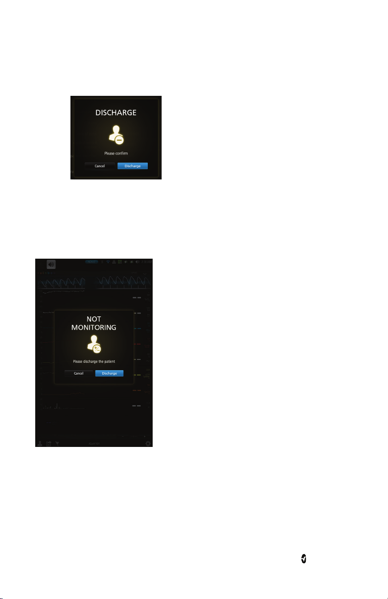
Root Chapter 4: Admit and Discharge to Patient SafetyNet
4. Press the Discharge confirmation button.
Note: Once patient is discharged from Root, or session is ended, the NIBP
parameter display will be cleared.
Not Monitoring Message
When the sensor is off the patient for an extended period of time, a Not Monitoring message
will appear on the screen. Acknowledge the message by pressing Cancel or Discharge. Press
Discharge to discharge the patient that is currently admitted on the Root, or press Cancel to
keep the same patient admitted.
www.masimo.com 74 Masimo
Page 77

Root Chapter 4: Admit and Discharge to Patient SafetyNet
Monitoring Resumed Message
When the sensor is taken off and placed back onto a patient, a Monitoring Resumed message
will appear on the Root screen.
If this is a new patient, press Discharge on the screen to discharge the previous patient. If the
same patient is being monitored, press Confirm to continue monitoring the same patient.
Electronic Medical Record (EMR) Push
The Electronic Medical Record (EMR) Push feature allows clinicians to send validated patient
vitals data from any of the Masimo devices, MOC-9 modules, or Iris devices connected to Root
directly to a Patient Data Management System, such as an Electronic Medical Record (EMR).
Determining EMR Push is Active
When connected to a configured Patient SafetyNet or Iris Gateway, the EMR Push icon
appears on the bottom of the Root main/home screen when it is active.
Note: To use this feature, Masimo Patient SafetyNet software version 5.0.1.0 or higher is
required.
Note: The system can be configured to require clinicians to provide access credentials to
activate the EMR Push feature.
www.masimo.com 75 Masimo
Page 78

Root Chapter 4: Admit and Discharge to Patient SafetyNet
Sending Data to the EMR
1. To send user data, select the EMR push icon at the bottom of the Root
main/home screen.
2. When the EMR Push screen appears, the following manual entry items can be
configured before sending data to EMR:
• Glucose
• Temperature
• Systolic blood pressure
• Diastolic blood pressure
• Level of Consciousness
• Pain Scale
• Supplemental O
See EMR Push Manual-Entry Item Settings on page 78 for information and settings.
2
www.masimo.com 76 Masimo
Page 79

Root Chapter 4: Admit and Discharge to Patient SafetyNet
3. The information gathered by the device is sent to the EMR, by default.
In the example below, note that the temperature has been obtained using the
Root with integrated temperature function.
4. Select to send the data, including any manual entries, to the EMR.
5. A Successfully Sent Data to EMR confirmation screen appears. Select OK.
6. Select OK to return Root to the main screen.
www.masimo.com 77 Masimo
Page 80

Root Chapter 4: Admit and Discharge to Patient SafetyNet
EMR Push Manual-Entry Item Settings
Options Description
Default
User Configurable Settings
Settings
Factory
Glucose
Patient Glucose
reading
NA User numeric input
RR* Respiration Rate -- -- and 1 to 70 in increments of 1
-- and from 80.1°F to 110.0°F in
Temperature**
Patient temperature
measurement
--
increments of 0.1
-- and from 26.8°C to 43.3°C in
increments of 0.1
Systolic**
Diastolic**
Level of
Consciousness
Pain Scale
Patient systolic
measurement
Patient diastolic
measurement
Patient level of
Consciousness
Level of pain patient
feels
-- -- and 41 to 260 in increments of 1
-- -- and 21 to 200 in increments of 1
--, A (Alert), V (Responds to Voice),
--
P (Responds to Pain), or U
(Unresponsive)
-- -- and 1 to 10 in increments of 1
* Not displayed unless an appropriate device or sensor is connected to Root.
** Not displayed if a temperature/blood pressure measurement is taken using Root with
noninvasive blood pressure and temperature.
www.masimo.com 78 Masimo
Page 81

Chapter 5: Radius-7
The Radius-7 is a patient wearable device for continuous monitoring when the patient is
ambulatory. It measures arterial oxygen saturation (SpO
(Pi), and Pleth Variability Index (PVi
®
), carboxyhemoglobin (SpCO®), total oxygen content (SpOC), methemoglobin
(SpHb
®
(SpMet
), Acoustic Respiration Rate (RRa®). It uses a Bluetooth® connection to transfer
®
) along with optional measurements of hemoglobin
), pulse rate (PR), perfusion index
2
parameter data to Root. When Radius-7 is connected to Root via Bluetooth, the device
automatically creates a Window that displays all the data from Radius-7.
Root also acts as a charging station for Radius-7. Radius-7 is docked onto Root via a Battery
Charging Adapter. See Radius-7 Operator's Manual for more information.
www.masimo.com 79 Masimo
Page 82

Page 83

Chapter 6: MOC-9
Flexible measurement expansion is enabled through MOC-9. It can display parameters and
measurements captured by SedLine, ISA Capnography, and third-party technologies in an
all-in-one view on Root.
When any MOC-9 module is connected, Root automatically creates a Window that displays all
the data from that module. The example below shows the “SedLine” and “Capnography”
Windows which display data from the SedLine brain function monitoring and ISA
capnography MOC-9 modules that are connected to Root.
Using MOC-9 Ports
Use a MOC-9 cable to connect other MOC-9 modules to Root.
To use an MOC-9 Port
1. Identify the MOC-9 end of the cable.
2. Orient the cable to fit correctly into an MOC-9 Port.
3. Insert the MOC-9 cable securely into any of the three (3) compatible ports on
www.masimo.com 81 Masimo
Root.
Page 84

Page 85

Chapter 7: Iris
Iris allows a variety of standalone devices to connect to Root. Patient data can be passed
through Root to Patient SafetyNet or Connectivity Gateway, which can send the data to
electronic health records.
Below is an example of one way Root can be used in a network setting using Patient
SafetyNet. Root receives and may display information from Radical-7, MOC-9 modules, as well
as standalone devices.
Ref. Description
1 Standalone devices connected via Iris (e.g., monitor, pump, ventilator)
2
Root
3 Patient SafetyNet View Station
4 Patient SafetyNet or Masimo Connectivity Gateway
5 Notification devices
6 Electronic Health Records system
www.masimo.com 83 Masimo
Page 86

Root Chapter 7: Iris
Iris Status Screen
Information about Iris Connectivity Ports is displayed on this screen, which is accessible by
selecting the Iris option on the Main Menu.
Connection
Status Color
Green
Yellow
Gray No standalone device is connected to the Iris Connectivity Port.
www.masimo.com 84 Masimo
Description of Connection
Standalone device is successfully connected to Root, and Root is
successfully connected to a Patient SafetyNet or Connectivity Gateway.
Standalone device connection to Iris adapter is established, but there is
no communication to SafetyNet or Connectivity Gateway
Page 87

Root Chapter 7: Iris
Additionally, the Ports are also mapped to the Iris icon on the Status Bar. When a standalone
device is connected to Root via one of the Ports, the corresponding part of the icon will be lit
green or yellow. In the example below, a standalone device is connected to Iris Connectivity
Port 1.
Port 1 (connected)
Port 3 Port 4
Port 2
Status and connection type are read-only and not configurable by the user. For more
information on Iris connectivity, see Instructions for Use or Operator’s Manual for the
appropriate version of Masimo Patient SafetyNet.
Using Iris Connectivity Ports
Use Iris Adapters and RJ-45 cables to connect standalone devices to Root.
To connect a standalone device via an Iris Connectivity Port:
1. Connect the Iris Adapter to the standalone device. Refer to the Iris Adapter
Directions for Use.
2. Connect the RJ-45 end of the Iris Adapter to any of the four (4) compatible Iris
Connectivity Ports on Root using a RJ-45 cable.
www.masimo.com 85 Masimo
Page 88

Page 89

Chapter 8: Messages
The following messages are specific to Root:
Message Explanation Next Step
Battery Charge is
Low.
MOC-9 module
Disconnected
(e.g. SedLine
Disconnected)
Radical-7
Disconnected
Radius-7
Disconnected
For additional messages, see Instructions for Use or Operator's Manuals for Radical-7,
Radius-7, and MOC-9 modules.
The internal battery needs to be
charged. System Status Lights
flash yellow.
A MOC-9 module is disconnected
from Root.
Radical-7 is disconnected from
Root.
Radius-7 is disconnected from
Root.
Charge Root's battery using AC
power.
Reconnect module or acknowledge
message by pressing the Alarm
Silence icon.
Reconnect Radical-7 or
acknowledge message by pressing
the Alarm Silence icon.
Reconnect Radius-7 or acknowledge
message by pressing the Alarm
Silence icon.
www.masimo.com 87 Masimo
Page 90

Page 91

Chapter 9: Troubleshooting
Troubleshooting Radical-7, Radius-7, and MOC-9 Modules
For information on troubleshooting values that are provided from Radical-7, Radius-7, and
MOC-9 modules, refer to their respective Instructions for Use or Operator's Manuals.
Troubleshooting Root
Symptom Possible Cause Correction
Power Button not
pressed long
enough.
Press Power Button for two (2) seconds.
Root does not turn on.
Root turns on, but
Main Screen is dim or
blank.
Touch functionality is
not responsive.
Not displaying data
from Radical-7,
Radius-7, or MOC-9
modules.
Iris screen does not
display connection
status for standalone
devices.
The battery may be
depleted.
One of the fuses is
not operating
properly.
The brightness
setting is not
correct.
Internal failure.
Connection error.
Connection error. Unplug and replug the Iris Adapter.
Connect Root to AC power to charge battery.
Replace the fuse. See Replacing the Fuses on
page 103.
Adjust the brightness setting. See Brightness
on page 53.
If the condition persists, Root requires service.
Contact Masimo Technical Support. See
Return Procedure on page 105.
Root requires service. Contact Masimo
Technical Support. See Return Procedure on
page 105.
Ensure that the connections are securely in
place and properly plugged in, or that the
cable is not defective. For Radius-7, ensure
that the device is paired with Root via
Bluetooth. Refer to Operator's Manual of
Radius-7 for more information.
www.masimo.com 89 Masimo
Page 92

Root Chapter 9: Troubleshooting
on
on
on
Symptom Possible Cause Correction
Iris screen does not
display connection
status for standalone
devices.
Root has a continuous
speaker tone.
Power Button does not
respond when
pressed.
Home Button does not
work when pressed.
Battery does not
charge.
Root Charging
Indicator illuminates
red.
Nurse Call does not
communicate.
Connection error.
Internal failure.
Power Button may
need to be pressed
for a longer time.
Internal failure.
Internal failure.
AC power cable may
be disconnected.
Internal failure.
Connection error.
If the problem persists, refer to instructions for
use or operator's manual for the connected
standalone devices or Iris section of the
instructions for use or operator’s manual for
the appropriate version of Patient SafetyNet.
To silence an alarm, press the Power Button for
eight (8) seconds. If alarm continues to sound,
Power Off Root. Root requires service. See
Return Procedure on page 105.
To Power On when turned off or in Sleep Mode,
press Power Button for two (2) seconds.
To Power Off when turned on or in Sleep Mode,
press the Power Button for eight (8) seconds.
Root requires service. See Return Procedure
page 105.
Root requires service. See Return Procedure
page 105.
Unplug and replug AC power cable.
Root requires service. See Return Procedure
page 105.
Unplug and replug Nurse Call connector.
See Nurse Call Setting Connections on page
104.
www.masimo.com 90 Masimo
Page 93

Chapter 10: Specifications
This chapter contains specifications of Root.
For information on the specifications of Radical-7, Radius-7, MOC-9 modules, and standalone
devices, see Directions for Use or Operator's Manuals for these devices.
Alarms
Audio Alarm
Type
System Status
Light Color
Audio Description
High Priority Flashing Red 10-pulse burst, pulse spacing: 0.250s, 0.250s,
0.500s, 0.250s, repeat time:10s
Medium
Priority
Flashing Yellow 3-pulse burst, pulse spacing: 0.375s, 0.375s, repeat
time: 7s
Low Priority Solid Yellow No audio
Nurse Call Specifications
The Nurse Call relays have the following electrical specifications per switch:
Parameter Specification
Max Voltage 36 VDC or 24 VAC peak
Connectors
Connector Type Number of Ports
Ethernet 10/100 Mbps 1
Nurse Call 1/4 inch round female 1
MOC-9 Masimo Connector 3
USB USB 2.0 2
Iris RS-232/RJ-45 4
www.masimo.com 91 Masimo
Page 94

Root Chapter 10: Specifications
Electrical
Root
AC Power requirements 100-240 VAC~, 47-63 Hz, 65VA Max
Fuses (2) 2 Amp, Metric, (5x20mm), 250V, 1500A Breaking Capacity
Battery
Type Lithium Ion
Voltage 10.8V (Nominal)
Capacity 4 hours*
Maximum Charging Time 4 hours
*This represents approximate run time at the lowest brightness, using a fully charged battery.
Environmental
Root
Operating Temperature 32°F to 122°F (0°C to 50°C)
Transport/Storage Temperature -40°F to 158°F (-40°C to 70°C)
Operating Humidity 10% to 95%, non-condensing
Storage Humidity 10% to 95%, non-condensing
500 mbar to 1060 mbar
Operating Air Pressure
-1000 ft to 18,000 ft
(-304 m to 5,486 m)
www.masimo.com 92 Masimo
Page 95

Root Chapter 10: Specifications
Touchscreen Display
Characteristic Description
Type Backlit Active Matrix TFT LCD
Resolution 1280 x 800 pixels
Size 10.1 in (25.65 cm) Diagonal
Color 24 bit RGB
Touchscreen Type Multi-Touch P-Cap
Wireless Specifications
Communication (Wi-Fi)
Type WLAN Radio: IEEE 802.11 a/b/g
Frequency
802.11a: 5180-5240 MHz, 5745-5825 MHz
802.11b/g: 2412-2462 MHz
Max Peak Output Power WLAN 17 dBm
Classification of Output
Power Rating
Conducted
Output Power Type Fixed at the Factory
Modulation Types OFDM, BPSK, CCK
Modulation Signals Analog and Digital
802.11a - 6, 9, 12, 18, 24, 36, 48, 54 Mbps.
Available Data Rates
802.11b - 1, 2, 5.5, 11 Mbps.
802.11g - 6, 9, 12, 18, 24, 36, 48, 54 Mbps.
www.masimo.com 93 Masimo
Page 96

Root Chapter 10: Specifications
Communication (Bluetooth)
Type Bluetooth
Frequency 2402-2480 MHz
Max Peak Output Power Bluetooth 1.3 dBm
Classification of Output
Power Rating
Conducted
Output Power Type Fixed at the Factory
Modulation Types DH5
Modulation Signals Analog and Digital
Available Data Rates Bluetooth 1 Mbps
Security and Authentication
Encryption 64/128-bit WEP, Dynamic WEP, WPA-TKIP, WPA2-AES
Authentication
Open System, Shared Key, Pre-Shared Key (PSK), 802.1X:
LEAP, PEAP< TTLS, TLS, EAP-FAST
Radio Compliance
USA FCC ID: VKF-RDS7A or VKF-RDS7
Model - RDS-7A or RDS-7
Canada IC:7362A-RDS7A or 7362A-RDS7
IC Model: RDS-7A or RDS-7
RSS-210
Europe
EN 300 328
EN 301 893
EN 301 489-1
EN 301 489-17
R & TTE Directive
www.masimo.com 94 Masimo
Page 97

Root Chapter 10: Specifications
Compliance
EMC Compliance
EN 60601-1-2, Class A
Software Compliance
EN 60601-1-4:1996 + A1: 1999
Electrical and Mechanical Safety
UL 60601-1:2003
CAN/CSA 22.2 No. 601.1:2005
IEC 60601-1 / UL 60601-1: 1988 + A1: 1991 + A2:1995
EN 60601-1: 1990 + AI: 1993 + A2:1995
IEC 60601-1:2005
IEC-60601-2-49:2001
IEC-60601-1-8
Equipment Classification per IEC 60601-1
Type of Protection
Class I (on AC power)
Internally powered (on battery power)
Degree of Protection of Electrical Shock Defibrillation proof BF-Applied Part
Protection against harm from liquid
ingress
IPX1 Protection against liquid drops falling
vertically
Mode of Operation Continuous Operation
www.masimo.com 95 Masimo
Page 98

Root Chapter 10: Specifications
Guidance and Manufacturer's Declaration-Electromagnetic Emissions
Guidance and Manufacturer's Declarations - Electromagnetic Emissions
The ME Equipment is intended for use in the electromagnetic environment specified below.
The customer or the user of the ME Equipment should assure that it is used in such an
environment.
Emission Test Compliance Electromagnetic Environment - Guidance
RF Emissions
CISPR 11
RF Emissions
CISPR 11
Harmonic
Emissions
IEC 61000-3-2
Voltage
Fluctuations /
Flicker Emissions
IEC 61000-3-3
Group 1
Class A
Class A
Complies
ME Equipment uses RF energy only for its internal
function. Therefore, its RF emissions are very low and are
not likely to cause any interference in nearby electronic
equipment.
For hospital environment only.
Not intended for use in a domestic environment.
www.masimo.com 96 Masimo
Page 99

Root Chapter 10: Specifications
Guidance and Manufacturer's Declaration-Electromagnetic Immunity
Guidance and Manufacturer's Declaration - Electromagnetic Immunity
The ME Equipment is intended for use in the electromagnetic environment specified below.
The customer or the user of the ME Equipment should assure that it is used in such an
environment.
Immunity Test IEC 60601
Electrostatic
discharge (ESD)
IEC 61000-4-2
Electrical fast
transient/burst
IEC 61000-4-4
Surge
IEC 61000-4-5
Voltage dips, short
interruptions and
voltage variations on
power supply input
lines.
IEC 61000-4-11
Test Level
+6 kV contact
+8 kV air
+2 kV for
power supply
lines.
+1 kV for
input/output
lines.
+1 kV differential
mode
+2 kV common
mode
100% for 0.5
cycle
60% for 5
cycles
30% for 25
cycles
100% for 5
seconds
Compliance
Level
+6 kV
contact
+8 kV air
-- Mains power quality should be that of
-- Mains power quality should be that of
-- Mains power quality should be that of
Electromagnetic Environment Guidance
Floors should be wood, concrete or
ceramic tile. If floors are covered with
synthetic material, the relative
humidity should be at least 30%.
a typical commercial or hospital
environment.
a typical hospital environment.
a typical commercial or hospital
environment. Root provides a battery
for continued operation during power
mains interruption for a maximum of 4
hours.
Power frequency (50
/ 60 Hz) magnetic
field.
IEC 61000-4-8
www.masimo.com 97 Masimo
3 A/m 3 A/m Power frequency magnetic fields
should be at levels characteristic of
typical location in a typical hospital
environment.
Page 100

Root Chapter 10: Specifications
should be
Guidance and Manufacturer's Declaration - Electromagnetic Immunity
Conducted RF
IEC 61000-4-6
Radiated RF
IEC 61000-4-3
3 Vrms
150 kHz to 80
MHz
3 V/m
80 MHz to 2.5
GHz
3 Vrms
Portable and mobile RF
communications equipment
used no closer to any part of the ME
Equipment, including cables, than the
recommended separation distance
calculated from the equation
applicable to the frequency of the
transmitter.
Recommended separation distance
3 V/m
80 MHz to 800 MHz
800 MHz to 2.5 GHz
where P is the maximum output power
rating of the transmitter in watts (W)
according to the transmitter
manufacturer and d is the
recommended separation distance in
meters (m).
Field strengths from fixed RF
transmitters, as determined by an
electromagnetic site survey
a
, should
be less than the compliance level in
each frequency rangeb.
Interference may occur in the vicinity
of equipment marked with the
following symbol:
Note 1: At 80 MHz and 800 MHz, the higher frequency range applies.
Note 2: These guidelines may not apply in all situations. Electromagnetic propagation is
affected by absorption and reflection from structures, objects and people.
www.masimo.com 98 Masimo
 Loading...