

Page 1
OPERATOR’S
MANUAL
Covers:
Rad-57c:
with SpO2 and SpCO
Rad-57m:
with SpO2 and SpMet
Rad-57cm:
with SpO
2,
SpCO
and SpMet
Signal Extraction
Pulse CO-Oximeter™
Masimo Rainbow® SET
®
Page 2

Signal Extraction Pulse CO-Oximeter™
OPERATOR'S MANUAL
Page 3

Page 4

Rad-57 Signal Extraction Pulse CO-Oximeter Operator’s Manual
The Rad-57 Signal Extraction Pulse CO-Oximeter Operating Instructions intend to provide the nec-
essary information for proper operation of all Rad-57 Pulse CO-Oximeter models.
General knowledge of Pulse CO-Oximetry and an understanding of the features and functions of
the Rad-57 Signal Extraction Pulse CO-Oximeter models are prerequisites for proper use.
Do not operate any of the Rad-57 Signal Extraction Pulse CO-Oximeter models without completely
reading and understanding these instructions.
NOTICE
Purchase or possession of this device does not carry any express or implied license to use with
replacement parts which would, alone or in combination with this device, fall within the scope of one
of the relating patents.
CAUTION:
FEDERAL LAW (U.S.) RESTRICTS THIS DEVICE TO SALE BY OR ON THE ORDER OF A
PHYSICIAN.
For further information contact:
Masimo Corporation
40 Parker
Irvine, CA 92618
USA
Tel.: 949-297-7000
Fax.: 949-297-7001
www.masimo.com
EU Authorized Representative for Masimo Corporation:
MDSS GmbH
Schiffgraben 41
30175 Hannover, Germany
Tel.: +49-511-62 62 86 30
Fax.: +49-511-62 62 86 33
MEDICAL ELECTRICAL EQUIPMENT WITH RESPECT TO ELECTRIC
SHOCK, FIRE AND MECHANICAL HAZARDS ONLY IN ACCORDANCE
WITH UL 60601-1/CAN/CSA C22.2 No. 601.1
80fk
Covered by one or more of the following U.S. Patents: RE38,492, RE38,476, 7,221,971, 7,215986,
7,186,966, 6,979,812, 6,861,639, 6,850,787, 6,826,419, 6,816,741, 6,745,060, 6,699,194,
6,684,090,, 6,654,624, 6,650,917, 6,643,530, 6,606,511, 6,515,273, 6,501,975, 6,463,311,
6,430,525, 6,388,240, 6,360,114, 6,263,222, 6,236,872, 6,229,856, 6,206,830, 6,157,850,
6,067,462, 6,011,986, 6,002,952, 5,919,134, 5,769,785, 5,758,644, 5,685,299, 5,632,272,
5,490,505, 5,482,036, international equivalents, or one or more of the patents referenced at www.
masimo.com/patents.htm. Other patents pending.
© 2009 Masimo Corporation. Masimo, , SET, LNCS, LNOP, Signal IQ, Discrete Saturation
Transform, DST, FastSat and SpCO are registered trademarks of Masimo Corporation.
Rad-57, Rad-57c, Rad-57m, Rad-57cm, SIQ, LNOPv, SpMet, Pulse CO-Oximeter and APOD are
trademarks of Masimo Corporation.
EC REP
Page 5

Rad-57 Signal Extraction Pulse CO-Oximeter Operator’s Manual
SAFETY INFORMATION, WARNINGS, CAUTIONS AND NOTES
The Rad-57™ Handheld Pulse CO-Oximeter™ is designed to minimize the possibility
of hazards from errors in the software program by following sound engineering design
processes, Risk Analysis and Software Validation.
■ Explosion hazard. Do not use the Pulse CO-Oximeter in the presence of flammable
anesthetics or other flammable substance in combination with air, oxygen-enriched
environments, or nitrous oxide.
■ High intensity extreme lights (such as pulsating strobe lights) directed on the sensor,
may not allow the Pulse CO-Oximeter to obtain vital sign readings.
■ The Pulse CO-Oximeter is NOT intended for use as an apnea monitor.
■ A Pulse CO-Oximeter should be considered an early warning device. As a trend
towards patient hypoxemia is indicated, blood samples should be analyzed by
laboratory instruments to completely understand the patient’s condition.
■ Pulse rate measurement is based on the optical detection of a peripheral flow pulse
and therefore may not detect certain arrhythmias. The pulse oximeter should not be
used as a replacement or substitute for ECG based arrhythmia analysis.
■ The Pulse CO-Oximeter is to be operated by qualified personnel only. This manual,
accessory directions for use, all precautionary information, and specifications should
be read before use.
■ Electric shock hazard. Do not open the Pulse CO-Oximeter cover except to replace
the batteries. Only a qualified operator may perform maintenance procedures
specifically described in this manual. Refer servicing to Masimo for repair of this
equipment.
■ As with all medical equipment, carefully route patient cabling to reduce the possibility
of patient entanglement or strangulation.
■ Do not place the Pulse CO-Oximeter or accessories in any position that might cause
it to fall on the patient. Do not lift the Pulse CO-Oximeter by the patient cable.
■ Interfering Substances: SpO
2
is a functional calculation of arterial oxygen saturation.
Carboxyhemoglobin and methemoglobin may erroneously increase SpO2 readings.
The level of increase is approximately equal to the amount of carboxyhemoglobin and/
or methemoglobin present. Dyes, or any substance containing dyes, that change usual
blood pigmentation may cause erroneous readings.
■ Severe anemia may cause erroneous SpO2 readings.
■ Elevated levels of Total Bilirubin may lead to inaccurate SpO2 measurements.
■ Hemoglobin synthesis disorders may cause erroneous SpHb readings.
■ Do not use the Pulse CO-Oximeter or oximetry sensors during magnetic resonance
imaging (MRI) scanning. Induced current could potentially cause burns. The Pulse
CO-Oximeter may affect the MRI image, and the MRI unit may affect the accuracy of
the oximetry measurements.
■ If using Pulse CO-Oximetry during full body irradiation, keep the sensor out of the
radiation field. If sensor is exposed to the radiation, the reading might be inaccurate
or the device might read zero for the duration of the active radiation period.
ii
Page 6

Rad-57 Signal Extraction Pulse CO-Oximeter Operator’s Manual
iii
SAFETY INFORMATION, WARNINGS, CAUTIONS AND NOTES
■ Always remove the sensor from the patient and completely disconnect the patient
from the Pulse CO-Oximeter before bathing the patient.
■ Do not place the Pulse CO-Oximeter where the controls can be changed by the patient.
■ Do not place the Pulse CO-Oximeter face against a surface. This will cause the alarm
to be muffled.
■ Do not place the Pulse CO-Oximeter on electrical equipment that may affect the
Pulse CO-Oximeter, preventing it from working properly.
■ Do not expose the Pulse CO-Oximeter to excessive moisture such as direct exposure
to rain. Excessive moisture can cause the Pulse CO-Oximeter to perform inaccurately
or fail.
■ Do not place containers containing liquids on or near the Pulse CO-Oximeter. Liquids
spilled on the Pulse CO-Oximeter may cause it to perform inaccurately or fail.
■ Failure of Operation - If the Pulse CO-Oximeter fails any part of the setup
procedures remove the Pulse CO-Oximeter from operation until qualified service
personnel have corrected the situation.
■ Patient Safety - If a sensor is damaged in any way, discontinue use immediately.
■ Disposal of product - Comply with local laws in the disposal of the device and/or its
accessories.
■ The Pulse CO-Oximeter can be used during defibrillation, but the readings may be
inaccurate for up to 20 seconds.
■ This equipment has been tested and found to comply with the limits for medical
devices to the EN 60601-1-2: 2002, Medical Device Directive 93/42/EEC. These limits
are designed to provide reasonable protection against harmful interference in a typical
medical installation. This equipment generates, uses and can radiate radio frequency
energy and, if not installed and used in accordance with the instructions, may cause
harmful interference to other devices in the vicinity. However, there is no guarantee
that interference will not occur in a particular installation. If this equipment does
cause harmful interference to other devices, which can be determined by turning the
equipment off and on, the user is encouraged to try to correct the interference by one
or more of the following measures:
■ Reorient or relocate the receiving device.
■ Increase the separation between the equipment.
■ Consult the manufacturer for help.
■ A functional tester cannot be utilized to assess the accuracy of the Pulse CO-Oximeter
or any sensors.
Page 7

Rad-57 Signal Extraction Pulse CO-Oximeter Operator’s Manual
table of contents
iv
SECTION 1 - OVERVIEW
About this manual .......................................................................................................... 1-1
Warnings, Cautions and Notes ...................................................................................... 1-2
Product Description .......................................................................................................1-3
Model Summary ....................................................................................................... 1-3
Features and Benefits .............................................................................................. 1-3
Indications for use .................................................................................................... 1-4
Pulse CO-Oximetry ........................................................................................................ 1-5
SpO
2
General Description........................................................................................ 1-5
SpCO General Description ....................................................................................... 1-5
SpMet General Description ...................................................................................... 1-5
Principle of Operation ............................................................................................... 1-6
Functional vs. Fractional Saturation ......................................................................... 1-6
Measured vs. Calculated Values .............................................................................. 1-7
Masimo SET Signal Extraction Technology for SpO2 measurements ...................... 1-7
SpCO and SpMet measurements during patient motion ......................................... 1-7
Masimo SET Parallel Engines .................................................................................. 1-8
Masimo SET DST® .................................................................................................. 1-8
SECTION 2 - SYSTEM DESCRIPTION
Introduction .................................................................................................................... 2-1
Rad-57c Front Panel Controls .......................................................................................2-2
Rad-57m Front Panel Controls ......................................................................................2-4
Rad-57cm Front Panel Controls ....................................................................................2-6
Rad-57 Rear Panel (all models) ....................................................................................2-8
Symbols .................................................................................................................... 2-9
SECTION 3 - SETUP
Introduction .................................................................................................................... 3-1
Unpacking and Inspection .............................................................................................3-1
Preparation for Monitoring .............................................................................................3-1
Power Requirements ................................................................................................ 3-1
Monitor Setup ................................................................................................................3-2
Initial Setup............................................................................................................... 3-2
SECTION 4 - OPERATION
Introduction .................................................................................................................... 4-1
Basic Operation ............................................................................................................. 4-1
General Setup and Use ............................................................................................ 4-1
Default Settings ........................................................................................................ 4-3
Successful SpO
2
Monitoring .......................................................................................... 4-4
Masimo Sensors....................................................................................................... 4-4
Numeric Display - SpO2 ........................................................................................... 4-4
Numeric Display - Pulse Rate ................................................................................. 4-5
Numeric Display - SpCO .......................................................................................... 4-5
Numeric Display - SpMet ......................................................................................... 4-5
Numeric Display - PI ................................................................................................ 4-5
Low Signal IQ (Low SIQ).......................................................................................... 4-5
Low Perfusion ........................................................................................................... 4-6
Actions To Be Taken ................................................................................................ 4-6
Sensitivity ................................................................................................................. 4-7
Page 8

Rad-57 Signal Extraction Pulse CO-Oximeter Operator’s Manual
v
table of contents
Battery Level Indicator.............................................................................................. 4-7
Low Battery Audible Alarm ....................................................................................... 4-8
Normal Patient Monitoring .............................................................................................4-9
Setup Menu.................................................................................................................. 4-10
Menu Navigation .................................................................................................... 4-10
Setup Menu Level 1 – Alarm Volume and Alarm Silence ...................................... 4-10
Setup Menu Level 2 – Alarm Limits ....................................................................... 4-10
Setup Menu Level 3 – Sensitivity, Averaging, FastSat and SmartTone ..................4-11
Setup menu Level 4 - Trend Settings ..................................................................... 4-11
Setup Menu Level 5 - LED brightness and Factory Defaults ................................. 4-12
Menu selection ....................................................................................................... 4-12
Power Off ................................................................................................................ 4-12
Special Menu ............................................................................................................... 4-12
Special Menu – Line Frequency Configuration ............................................................ 4-13
Trend Setup and Use ................................................................................................... 4-14
Introduction ............................................................................................................. 4-14
TrendCom Utility Installation ................................................................................... 4-14
TrendCom Utility Operation .................................................................................... 4-14
Erasing Trend Memory ........................................................................................... 4-15
Trend Data Format ................................................................................................. 4-15
Sample Trend Output .............................................................................................. 4-16
SECTION 5 - ALARMS / MESSAGES
Alarm Indication ............................................................................................................. 5-1
Alarm Limits ...................................................................................................................5-1
Alarm Silence ........................................................................................................... 5-3
Alarm Silenced Indicator .......................................................................................... 5-3
Messages ................................................................................................................. 5-4
SECTION 6 - TROUBLESHOOTING
Troubleshooting .............................................................................................................. 6-1
SECTION 7 - SPECIFICATIONS
Rad-57 Family Specifications ........................................................................................7-1
Performance ............................................................................................................. 7-1
Accuracy ................................................................................................................... 7-1
Electrical ................................................................................................................... 7-2
Environmental........................................................................................................... 7-2
Physical characteristics ............................................................................................ 7-2
SECTION 8 - SENSOR AND PATIENT CABLES
Introduction .................................................................................................................... 8-1
Selecting a Sensor ................................................................................................... 8-1
Sensor Application Instructions ................................................................................ 8-1
Masimo Rainbow
®
Sensors............................................................................................ 8-2
Rainbow Reusable Sensors ..................................................................................... 8-2
Rainbow Adhesive Sensors ..................................................................................... 8-2
Masimo SpO2 Sensors .................................................................................................. 8-2
Red Reusable Sensors ........................................................................................... 8-2
LNOP® Reusable Sensors ........................................................................................................... 8-3
SECTION 4 - OPERATION (CONTINUED)
Page 9

Rad-57 Signal Extraction Pulse CO-Oximeter Operator’s Manual
table of contents
vi
LNOP® Adhesive Sensors ....................................................................................... 8-3
LNOP
®
Specialty Sensors ....................................................................................... 8-3
LNCS® Reusable Sensors ...................................................................................... 8-3
LNCS® Adhesive Sensors ...................................................................................... 8-4
LNOPv™ Adhesive Sensors ............................................................................................ 8-4
Sensor Accuracy ..................................................................................................... 8-4
Cleaning And Reuse Of Masimo Reusable Sensors and Cables ............................ 8-4
Reattachment of Single Use Adhesive Sensors ...................................................... 8-4
SECTION 9- SERVICE / MAINTENANCE
Introduction .................................................................................................................... 9-1
Cleaning ......................................................................................................................... 9-1
Battery Replacement ................................................................................................ 9-2
Performance Verification ................................................................................................ 9-3
Power-On Self-Test ................................................................................................... 9-3
Key Press Button Test .............................................................................................. 9-3
Alarm Limit Test ........................................................................................................ 9-3
LED Brightness ........................................................................................................ 9-3
Service and Repair ........................................................................................................9-4
Repair Policy ............................................................................................................ 9-4
Return Procedure ..................................................................................................... 9-4
Sales & End-user License Agreement .................................................................... 9-5
Warranty .........................................................................................................................9-5
Exclusions ...................................................................................................................... 9-5
End-user License .......................................................................................................... 9-6
Restrictions ................................................................................................................... 9-7
SECTION 10- ACCESSORIES
Accessories.................................................................................................................. 10-1
SECTION 8 - SENSOR AND PATIENT CABLES (CONTINUED)
Page 10

Rad-57 Signal Extraction Pulse CO-Oximeter Operator’s Manual 1-1
1
overview
About this Manual
This manual explains how to set up and use the Rad-57c, Rad-57m and Rad-57cm Signal
Extraction Pulse CO-Oximeter. These three products will be generally referred to as the Rad-
57. Features and specifications apply to all models unless otherwise noted. Important safety
information relating to general use of the Rad-57 appears before this introduction. Other
important safety information is located throughout the manual where appropriate.
Read the entire safety information section before you operate the monitor.
In addition to the safety section, this manual includes the following sections:
SECTION 1 OVERVIEW gives a general description of Pulse CO-Oximetry.
SECTION 2 SYSTEM DESCRIPTION describes the Rad-57 system, functions and
features.
SECTION 3 SETUP describes how to setup the Rad-57 for use.
SECTION 4 OPERATION describes the operation of the Rad-57.
SECTION 5 ALARMS AND MESSAGES describes the alarm system messages.
SECTION 6 TROUBLESHOOTING gives troubleshooting information.
SECTION 7 SPECIFICATIONS gives the detailed specifications of the Rad-57.
SECTION 8 SENSORS AND PATIENT CABLES outlines how to use and care for
Masimo Rainbow SET, LNOP
®
, LNOPv™ and LNCS® sensors, Masimo
Rainbow SET patient cables and Masimo SET patient cables.
SECTION 9 SERVICE AND MAINTENANCE describes how to maintain, service and
obtain repair for the Rad-57.
SECTION 10 ACCESSORIES
Page 11

1-2 Rad-57 Signal Extraction Pulse CO-Oximeter Operator’s Manual
1
Warnings, Cautions and Notes
Please read and follow any warnings, cautions and notes presented throughout this
manual. An explanation of these labels are as follows:
A WARNING is provided when actions may result in a serious outcome (i.e., injury,
serious adverse affect, death) to the patient or user. Look for text in a gray shaded box.
Sample of Warning:
WARNING: THIS IS A SAMPLE OF A WARNING STATEMENT.
A CAUTION is given when any special care is to be exercised by the patient or user to
avoid injury to the patient, damage to this device or damage to other property.
Sample of Caution:
CAUTION: THIS IS A SAMPLE OF A CAUTION STATEMENT.
A NOTE is provided when extra general information is applicable.
Sample of Note:
NOTE: This is a sample of a Note.
overview
1
Page 12

Rad-57 Signal Extraction Pulse CO-Oximeter Operator’s Manual 1-3
1
overview
Product Description
The Rad-57 Handheld Pulse CO-Oximeter with Masimo Rainbow
®
SET® Technology is
a noninvasive, arterial oxygen saturation and pulse rate monitor. The Rad-57 features a
multicolored LED display that continuously displays numeric values for SpO
2
and pulse
rate, a Low Signal IQ Indicator (Low SIQ) indicator, alarm status, alarm silence and battery
life.
Certain models include LED indicator bars for Perfusion Index (PI), Carboxyhemoglobin
saturation (%SpCO), Methemoglobin percentage (%SpMet), and SpCO/SpMet sensor
connected.
MODEL SUMMARY
All models include SpO
2
and pulse rate.
MODEL FEATURES
Rad-57c Includes SpCO and PI
Rad-57m Includes SpMet and PI
Rad-57cm Includes SpCO, SpMet and PI
The following list outlines the key features and benefits of the Rad-57 Handheld Pulse
CO-Oximeter.
FEATURES AND BENEFITS
■ Clinically proven Masimo SET
®
technology performance
■ Proven for accurate SpO
2
and pulse rate monitoring in motion and low perfusion
environments
■ SpO
2
, pulse rate, Perfusion Index, % SpCO* and SpMet* displays
■ Low Signal IQ (SIQ™) indicator
■ Lightweight, convenient handheld design
■ Over 8 hours of continuous use on 4 “AA” alkaline batteries
■ Visual battery life indicator
■ Audible Alarm for sensor-off and low battery
■ Alarms for high/low SpO
2
, high/low pulse rate, SpCO* and SpMet*
■ FastSat
®
(for SpO2 measurement)
■ Three sensitivity levels - Max, Normal and APOD
TM
(for SpO2 measurement)
■ 72 hours of trending memory
■ Adjustable alarm volume
■ Adjustable averaging 2 to 16 seconds
*See Model Summary for applicable device.
Page 13

1-4 Rad-57 Signal Extraction Pulse CO-Oximeter Operator’s Manual
1
INDICATIONS FOR USE
The Rad-57 and accessories are indicated for the continuous, noninvasive monitoring of
functional oxygen saturation of arterial hemoglobin (SpO
2
), pulse rate, carboxyhemoglobin
saturation (measured by an SpCO/SpMet sensor)* and methemoglobin saturation
(measured by a SpCO/SpMet sensor)*. The Rad-57 and accessories are indicated for use
with adult, pediatric and neonatal patients during both motion and no motion conditions,
and for patients who are well or poorly perfused in hospitals, hospital-type facilities, mobile
and home environments.
*See Model Summary for applicable device.
overview
1
Page 14

Rad-57 Signal Extraction Pulse CO-Oximeter Operator’s Manual 1-5
1
1
overview
Pulse CO-Oximetry
SpO2 GENERAL DESCRIPTION
Pulse oximetry is a continuous and non-invasive method of measuring the level of arterial
oxygen saturation in blood. The measurement is taken by placing a sensor on a patient,
usually on the fingertip for adults, and the hand or foot for neonates. The sensor connects
to the pulse oximetry device with a patient cable. The sensor collects signal data from the
patient and sends it to the device. The device displays the calculated data in two ways:
1) As a percent value for arterial oxygen saturation (SpO
2
)
2) As a pulse rate (PR)
The following figure shows the general monitoring setup.
SpCO GENERAL DESCRIPTION
Pulse CO-Oximetry is a continuous and non-invasive method of measuring the levels
of carbon monoxide concentration (SpCO) in arterial blood. It relies on the same basic
principles of pulse oximetry (spectrophotometry) to make its SpCO measurement. The
measurement is obtained by placing a sensor on a patient, usually on the fingertip for
adults and the hand or foot for infants. The sensor connects either directly to the Pulse
CO-Oximetry device or through a patient cable. The sensor collects signal data from the
patient and sends it to the device. The Rad-57c and Rad-57cm display the calculated data
as percentage value for the SpCO, which reflect blood levels of carbon monoxide bound
to hemoglobin.
SpMet GENERAL DESCRIPTION
Pulse CO-Oximetry is a continuous and non-invasive method of measuring the levels
of methemoglobin concentration (SpMet) in arterial blood. It relies on the same basic
principles of pulse oximetry (spectrophotometry) to make its SpMet measurement. The
measurement is obtained by placing a sensor on a patient, usually on the fingertip for
adults and the hand or foot for infants. The sensor connects either directly to the Pulse
CO-Oximetry or through a patient cable. The sensor collects signal data from the patient
and sends it to the device. The Rad-57m and Rad-57cm display the calculated data as
percentage value for the SpMet.
1
3
2
1. Device
2. Sensor
3. Patient Cable
Page 15
1-6 Rad-57 Signal Extraction Pulse CO-Oximeter Operator’s Manual
1
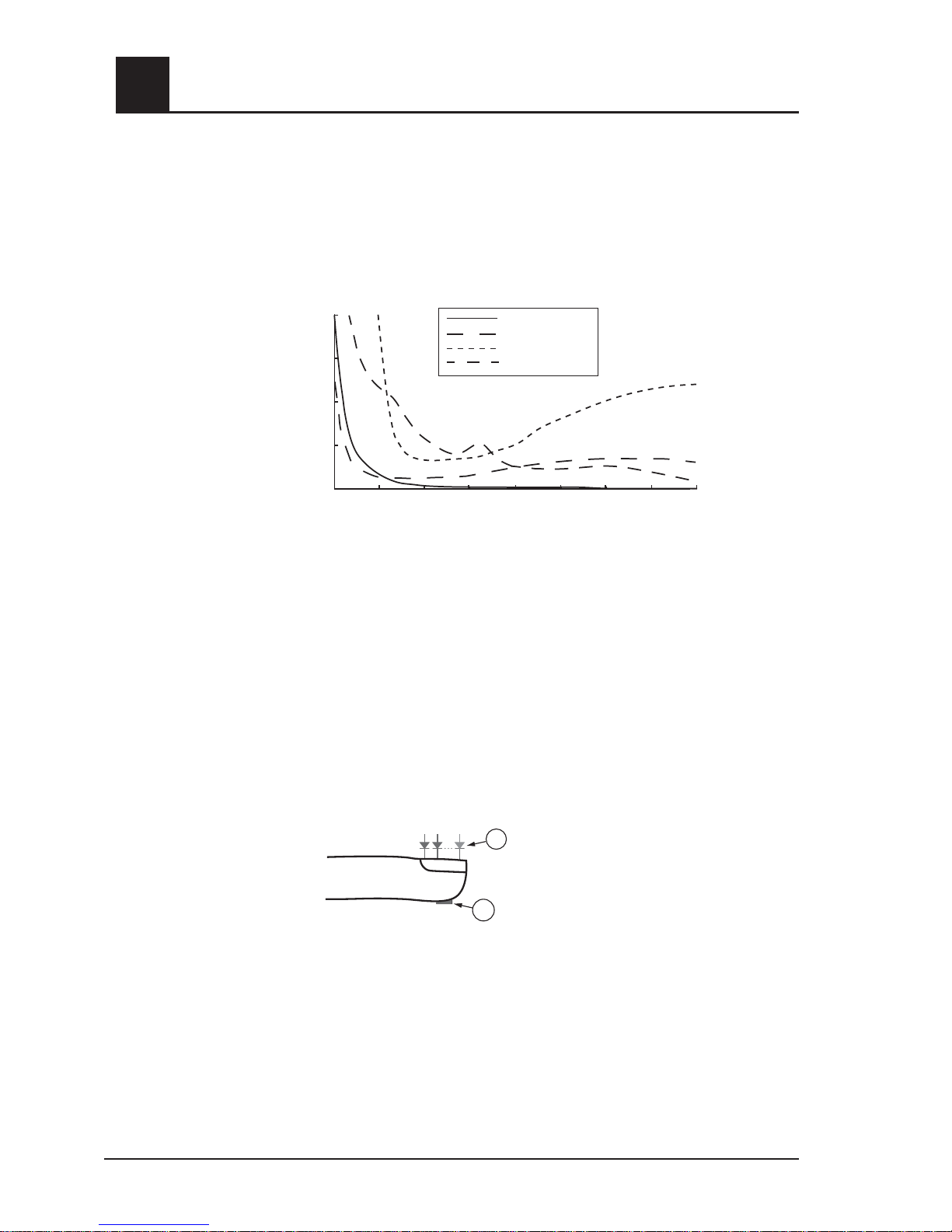
PRINCIPLE OF OPERATION
Pulse oximetry is governed by the following principles:
1. Oxyhemoglobin (oxygenated blood), deoxyhemoglobin (non-oxygenated blood),
carboxyhemoglobin (blood with carbon monoxide content) and methemoglobin
(blood with oxidized hemoglobin content) species differ in their absorption of visible
and infrared light (using spectrophotometry, see figure below).
2. The amount of arterial blood in tissue changes with your pulse (photoplethysography).
Therefore, the amount of light absorbed by the varying quantities of arterial blood
changes as well.
The Rad-57 Pulse CO-Oximeter uses a multi-wavelength sensor to distinguish between
oxygenated blood, deoxygenated blood, blood with carbon monoxide content and blood
with oxidized hemoglobin. The Rad-57 utilizes a sensor with various light-emitting diodes
(LEDs) that pass light through the site to a photodiode (detector). See figure below. Signal
data is obtained by passing various visible and infrared lights (LED’s, 500 to 1000nm)
through a capillary bed (for example, a fingertip, a hand, a foot) and measuring changes in
light absorption during the blood pulsatile cycle. This information may be useful to clinicians.
The maximum radiant power of the strongest light is rated at 22mW. The detector receives
the light, converts it into an electronic signal and sends it to the Rad-57 for calculation.
Once the Rad-57 receives the signal from the sensor, it utilizes Masimo Rainbow SET
signal extraction technology to calculate the patient’s functional oxygen saturation, blood
levels of carboxyhemoglobin (SpCO*), methemoglobin (SpMet*) and pulse rate. The SpCO
and SpMet measurements rely on a multiwavelength calibration equation to quantify the
percentage of carbon monoxide and methemoglobin in arterial blood. The maximum of
the skin surface temperature is measured at an ambient temperature of less than 106º F
(41º C). This is verified by Masimo sensor skin temperature test procedures.
* See Model Summary for applicable device.
overview
Rad-57cm Signal Extraction Pulse CO-Oximeter Operator’s Manual
1
600
650 700 750 800 850 900 950 1000
0
2
4
6
8
Wavelength (nm)
Absorption (mm-1)
Carboxyhemoglobin
Oxyhemoglobin
Methemoglobin
Deoxyhemoglobin
1
2
1. Light Emitting Diodes (LEDs)
(7 + wavelengths)
2. Detector
Page 16

Rad-57 Signal Extraction Pulse CO-Oximeter Operator’s Manual 1-7
1
Rad-57 Signal Extraction Pulse CO-Oximeter Operator’s Manual
1
overview
FUNCTIONAL VS. FRACTIONAL SATURATION
The Rad-57 is calibrated to measure and display functional saturation (SpO
2
): the amount
of oxyhemoglobin expressed as a percentage of the hemoglobin that is available to
transport oxygen. Note that carboxyhemoglobin is not capable of transporting oxygen, but
is recognized as oxygenated hemoglobin by conventional pulse oximetry.
MEASURED VS. CALCULATED VALUES
SpO2, SpCO* and SpMet* measurements that can be obtained from the Rad-57 are
commonly compared to invasive measurements obtained from blood gas samples. When
comparing invasive and noninvasive measurements and interpreting values, caution
should be used, as the calculated values obtained from the blood gas sample may differ
from the SpO2, SpCO and SpMet measurements of the Pulse CO-Oximeter. In the case
of SpO2, different results are usually obtained from the arterial blood gas sample if the
calculated measurement is not appropriately corrected for the effects of variables that
shift the relationship between the partial pressure of oxygen (PO2) and saturation, such
as: pH, temperature, the partial pressure of carbon dioxide (PCO2), 2,3-DPG, and fetal
hemoglobin. In the case of SpCO and SpMet, in addition to the effects of temperature and
pH, different results are also expected if concentration of methemoglobin in the blood gas
sample are abnormal (less than 90% for arterial oxygen saturation, and greater than 2%
for methemoglobin concentration). As blood gas samples are usually taken over a period
of 20 seconds (the time it takes to draw the blood) a meaningful comparison can only be
achieved if the oxygen saturation, carboxyhemoglobin and methemoglobin concentration of
the patient are stable and not changing over the period of time that the blood gas sample
is taken.
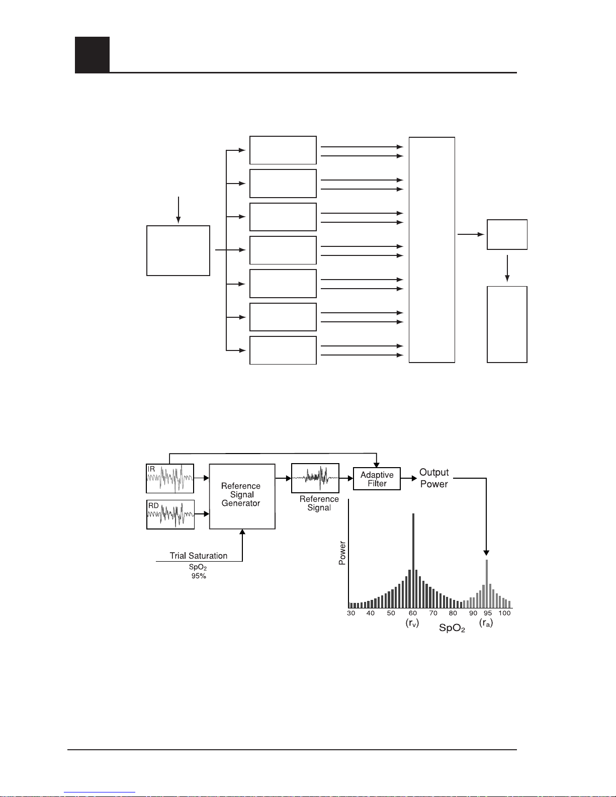
MASIMO SET SIGNAL EXTRACTION TECHNOLOGY FOR SpO
2
MEASUREMENTS
Masimo Signal Extraction Technology’s signal processing differs from conventional
pulse oximeters. Conventional pulse oximeters assume that arterial blood is the only
blood moving (pulsating) in the measurement site. During patient motion, however, the
non-arterial blood also moves, causing conventional pulse oximeters to read low values,
because they cannot distinguish between the arterial and venous blood movement
(sometimes referred to as noise). Masimo SET pulse oximetry utilizes parallel engines and
adaptive digital filtering. Adaptive filters are powerful because they are able to adapt to the
varying physiologic signals and/or noise and separate them by looking at the whole signal
and breaking it down to its fundamental components. The Masimo SET signal processing
algorithm, Discrete Saturation Transform
®
(DST)®, reliably identifies the noise, isolates it
and, using adaptive filters, cancels it. It then reports the true arterial oxygen saturation for
display on the monitor.
SpCO AND SpMet MEASUREMENTS DURING PATIENT MOTION
The Rad-57 displays measurements of SpCO* and SpMet* during patient motion. However,
because of the changes in the physiological parameters such as blood volume, arterialvenous coupling, etc. that occur during patient motion, the accuracy of such measurements
may not be readable during excessive motion.
* See Model Summary for applicable device.
Page 17
1-8 Rad-57 Signal Extraction Pulse CO-Oximeter Operator’s Manual
1
MASIMO RAINBOW SET PARALLEL ENGINES
This figure is for conceptual purposes only.
MASIMO SET DST
®
overview
Intermediate Calculations
Confidence
Intermediate Calculations
Confidence
Intermediate Calculations
Confidence
Intermediate Calculations
Confidence
Intermediate Calculations
Confidence
Intermediate Calculations
Confidence
Intermediate Calculations
Confidence
Pre-Processing &
Data Reduction
Digitized, Filtered &
Normalized
LED
Wavelengths
R/IR
(Conventional
Pulse Oximetry)
DST
Adaptive
Filter
SST ™
®
FST:
Proprietary
Algorithm 3
FST:
Proprietary
Algorithm 4
Rainbow
Specific
Algorithms
Pulse
Rate
Algorithm
Confidence
Based
Arbitrator
Post
Processor
%SpO
2
%SpCO
%SpMet
PI
PR
Page 18

Rad-57 Signal Extraction Pulse CO-Oximeter Operator’s Manual 2-1
2
Introduction
The Rad-57 is a full featured Pulse CO-Oximeter designed for ease of operation. All pulse
oximetry measurement information, as well as device status data, is displayed on the front
panel of the device. All user input is handled by control buttons on the front panel and the
sensor cable connection is located at the top edge of the device.
The Rad-57 is powered by 4 “AA” alkaline batteries, which provides a minimum of 8 hours
of battery life.
■ Rad-57 offers full Masimo Rainbow SET Technology in a small, hand held device.
■ Rad-57 supports the full line of Masimo sensors (see Section 8, sensors and
patient cables).
■ Provides 72 hours of trending memory
A Direct Connect Rainbow reusable sensor or patient cable or a Direct Connect Red
reusable sensor or patient cable attaches to the patient cable connector on the top of the
Rad-57. The Rad-57 can be used either as a transport monitor or as a handheld Pulse
CO-Oximeter for spot checks.
2
system description
Page 19
2-2 Rad-57 Signal Extraction Pulse CO-Oximeter Operator’s Manual
2
system description
CONTROL / INDICATOR DESCRIPTION
1
Patient Cable Connector
Connects to a Rainbow Sensor or Rainbow Patient Cable,
Red Sensor or a Red Patient Cable with an LNOP, LNOPv
or LNCS Sensor.
2
SpCO indicator
Slow flashing indicator: The confidence in the SpCO value
obtained is low.
Fast flashing indicator: Flashes when an SpCO alarm
condition exists.
3
Saturation (%SpO2) and
Carboxyhemoglobin
(%SpCO) Displays
The functional arterial hemoglobin oxygen saturation is
displayed in units of SpO2. When searching for a saturation
and pulse, it will flash dashed lines.
Refer to the Display Button description.
4
%SpCO Bar
Illuminates when SpCO capable sensor is attached. Bar will
flash for SpCO alarm conditions. Continuously indicates the
concentration of carboxyhemoglobin in increments of: 3, 6, 9,
12, 15, 20, 25, 30, 35, > 40.
5
Pulse Rate Display
The pulse rate in beats per minute (bpm). When searching for
a saturation and pulse, it will flash dashed lines.
Rad-57c
Rad-57c Front Panel Controls
2
3
4
5
1
11
12
14
16
17
18
6
8
9
13
15
7
10
<3
6
9
12
15
20
25
30
35
>40
%SpCO
SpCO
Signal Extraction Pulse CO-Oximeter
%SpO
2
rainbow
%SpCO
1
2
3
1.75
>5
1.5
1.25
.5
.25
<.1
BPM
PI
Page 20

Rad-57 Signal Extraction Pulse CO-Oximeter Operator’s Manual 2-3
2
system description
CONTROL / INDICATOR DESCRIPTION
6
Display Button
Pressing this button will display the numeric SpCO value
in place of the SpO2 numeric value and CO in the place of
pulse rate. Pressing this button again will return to the SpO
2
/pulse rate numeric value.
7
Mode / Enter Button
Used to enter the setup menus and to select/activate certain
entries within the menu/setup system.
8
Next Button
Used within the menu/setup system to move through setup
options. Not active during normal patient monitoring.
9
Power On / Off
Press to turn the device on.
Press-and-hold for 2 seconds to turn the device off.
10
Battery Level Indicator
Four LED’s indicate the status of the battery. When the final
indicator begins flashing, replace the batteries.
11
Visual Alarm Indicator
Illuminates when any alarm condition exists. This indicator
may not be turned-off or otherwise over-ridden.
12
%SpO2 / %SpCO
Indicator
Indicator above label will illuminate to provide an additional
visual indication of the value currently being displayed.
13
PI
Perfusion Index, or PI, is a relative assessment of the
perfusion at the monitoring site. PI is displayed on a 10
segment LED bar, ranging from < .1% (very weak perfusion)
to >5% (strong perfusion). The highest LED will remain lit
continuously to allow a PI level to be viewed. The Perfusion
Index is the ratio of the AC (pulsatile) to DC (non-pulsatile)
components of the IR (Infrared) signal where the AC and DC
components correspond to the pulsatile and non-pulsatile
amounts of blood, respectively.
14
Low SIQ
Flashes to indicate low SpO2 Signal IQ. Refer to Section
4, Low Signal IQ.
15
Alarm Silenced Indicator
Flashes to indicate the alarm is temporarily silenced. A solid
illuminated light indicates that the alarms are permanently
silenced until the power is cycled or the alarms are enabled
per Setup Menu 1 in Section 4.
16
Alarm Silence Button
Push once to temporarily silence the alarm for 120 seconds.
Push a second time to return the device to standard alarm
monitoring.
17
Up button
Down button
During saturation monitoring, use these buttons to adjust the
volume of the pulse beep tone.
Within the menu/setup system, these buttons are used to
select values within each menu option.
18
Speaker
Provides audible indication of alarm conditions, pulse tone
and feedback for key-presses. Ensure the speaker is not
covered or the device is placed face-down on bedding or
other sound absorbing surface.
Page 21
2-4 Rad-57 Signal Extraction Pulse CO-Oximeter Operator’s Manual
2
system description
CONTROL / INDICATOR DESCRIPTION
1
Patient Cable
Connector
Connects to a Rainbow Sensor or Rainbow Patient Cable,
Red Sensor or a Red Patient Cable with an LNOP, LNOPv
or LNCS Sensor.
2
SpMet indicator
Slow flashing indicator: The confidence in the SpMet value
obtained is low.
Fast flashing indicator: Flashes when an SpMet alarm
condition exists.
3
Saturation (%SpO2)
Display
The functional arterial hemoglobin oxygen saturation is
displayed in units of SpO
2
. When searching for a saturation
and pulse, it will flash dashed lines.
4
%SpMet Bar
Illuminates when SpMet capable sensor is attached. Bar will
flash for SpMet alarm conditions. Continuously indicates the
concentration of Methemoglobin in increments: .5, 1-5, 7.5,
10, 15 >20%.
5
%SpMet / Pulse Rate
Display
Indicator above label will illuminate to provide an additional
visual indication of the SpMet value currently being
displayed.
The pulse rate in beats per minute (bpm). When searching
for a saturation and pulse, it will flash dashed lines.
Rad-57m
Rad-57m Front Panel Controls
2
3
4
5
1
11
12
14
16
17
18
6
8
9
13
15
7
10
.5
1
2
3
4
5
7.5
10
15
>20
SpMet
%SpMet
Signal Extraction Pulse CO-Oximeter
%SpO
2
1
2
3
1.75
>5
1.5
1.25
.5
.25
<.1
%SpMet
BPM
PI
rainbow
Page 22

Rad-57 Signal Extraction Pulse CO-Oximeter Operator’s Manual 2-5
2
system description
CONTROL / INDICATOR DESCRIPTION
6
Display Button
Pressing this button will display the numeric SpMet value
in place of the pulse rate numeric value until the SpMet
button is pressed again.
7
Mode / Enter Button
Used to enter the setup menus and to select/activate
certain entries within the menu/setup system.
8
Next Button
Used within the menu/setup system to move through setup
options. Not active during normal patient monitoring.
9
Power On / Off
Press to turn the device on.
Press-and-hold for 2 seconds to turn the device off.
10
Battery Level Indicator
Four LED’s indicate the status of the battery. When the
final indicator begins flashing, replace the batteries.
11
Visual Alarm Indicator
Illuminates when any alarm condition exists. This indicator
may not be turned-off or otherwise over-ridden.
12
%SpO2 Indicator
Indicator above label will illuminate to provide an additional
visual indication of the value currently being displayed.
13
PI
Perfusion Index, or PI, is a relative assessment of the
perfusion at the monitoring site. PI is displayed on a
10 segment LED bar, ranging from < .1% (very weak
perfusion) to >5% (strong perfusion). The highest LED will
remain lit continuously to allow a PI level to be viewed. The
Perfusion Index is the ratio of the AC (pulsatile) to DC (nonpulsatile) components of the IR (Infrared) signal where the
AC and DC components correspond to the pulsatile and
non-pulsatile amounts of blood, respectively.
14
Low SIQ
Flashes to indicate low SpO2 Signal IQ. Refer to Section
4, Low Signal IQ.
15
Alarm Silenced Indicator
Flashes to indicate the alarm is temporarily silenced.
A solid illuminated light indicates that the alarms are
permanently silenced until the power is cycled or the
alarms are enabled per Setup Menu 1 in Section 4.
16
Alarm Silence Button
Push once to temporarily silence the alarm for 120
seconds. Push a second time to return the device to
standard alarm monitoring.
17
Up button
Down button
During saturation monitoring, use these buttons to adjust
the volume of the pulse beep tone.
Within the menu/setup system, these buttons are used to
select values within each menu option.
18
Speaker
Provides audible indication of alarm conditions, pulse tone
and feedback for key-presses. Ensure the speaker is not
covered or the device is placed face-down on bedding or
other sound absorbing surface.
Page 23

2-6 Rad-57 Signal Extraction Pulse CO-Oximeter Operator’s Manual
2
system description
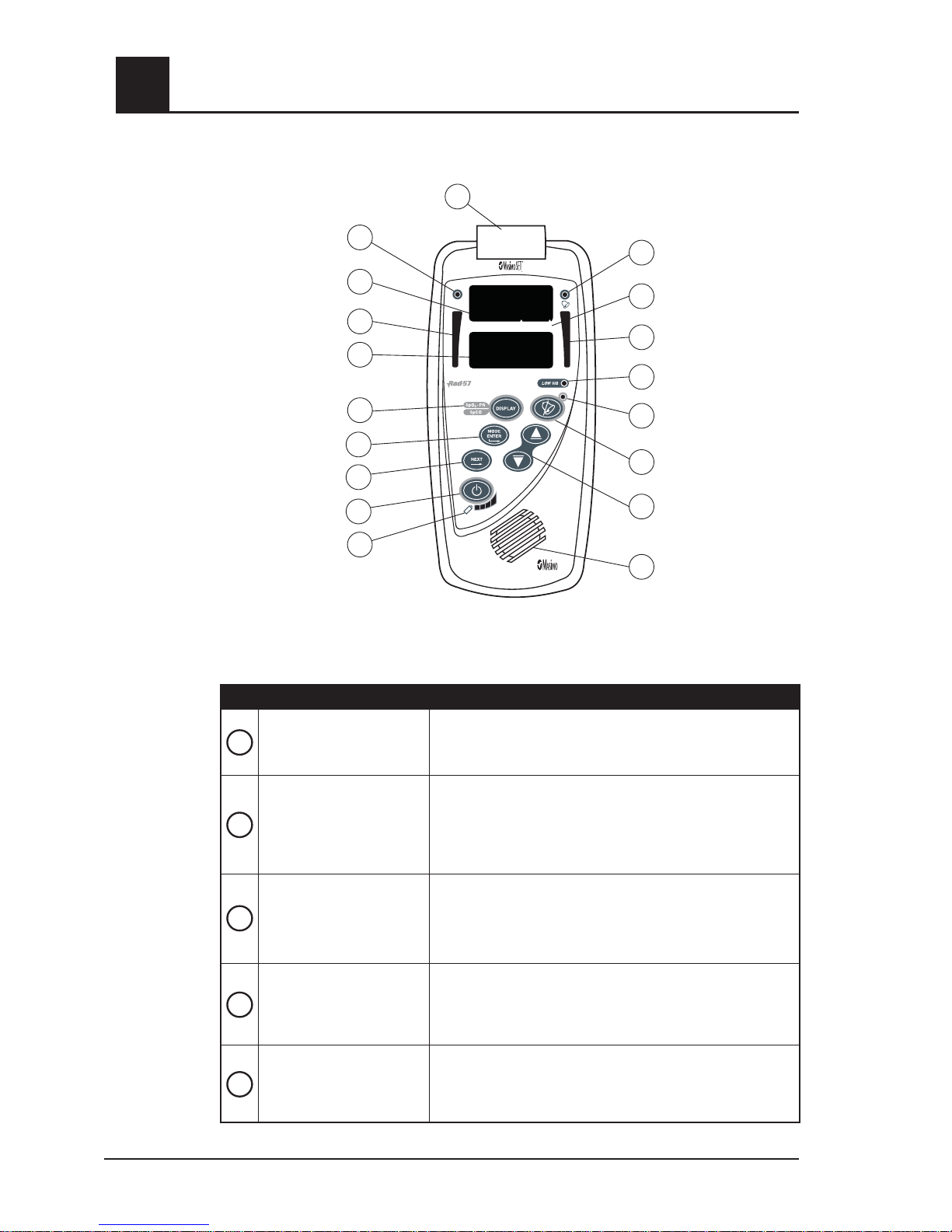
Rad-57cm
Rad-57cm Front Panel Controls
CONTROL / INDICATOR
DESCRIPTION
1
Patient Cable
Connector
Connects to a Rainbow Sensor or Rainbow Patient Cable,
Red Sensor or a Red Patient Cable with an LNOP, LNOPv
or LNCS Sensor.
2
Low PI Indicator
The Perfusion Index (PI) LED illuminates a constant light
when arterial pulsations are very low (weak perfusions).
3
Saturation
(%SpO2) and
Carboxyhemoglobin
(%SpCO) Displays
The functional arterial hemoglobin oxygen saturation is
displayed in units of SpO2. When searching for a saturation
and pulse, it will flash dashed lines.
See SpCO/SpMet Button description, below.
4
%SpCO Bar
Illuminates when SpCO capable sensor is attached. Bar will
flash for SpCO alarm conditions. Continuously indicates the
concentration of carboxyhemoglobin in increments of: 3, 6,
9, 12, 15, 20, 25, 30, 35, > 40.
5
Pulse Rate Display
and Methemoglobin
(%SpMet) Displays
The pulse rate in beats per minute (bpm). When searching
for a saturation and pulse, it will flash dashed lines.
See Display button description.
2
3
4
5
1
11
12
15
17
18
19
6
8
9
13
16
7
10
14
<3
6
9
12
15
20
25
30
35
>40
%SpCO
Signal Extraction Pulse CO-Oximeter
rainbow
Low PI
%SpO
2
%SpCO
%SpMet
BPM
%SpMet
.5
1
2
3
4
5
7.5
10
15
>20
Page 24

Rad-57 Signal Extraction Pulse CO-Oximeter Operator’s Manual 2-7
2
system description
CONTROL / INDICATOR DESCRIPTION
6
Display Button
Pressing this button will display the numeric SpCO value
in place of the SpO2 numeric value and the SpMet value in
place of the pulse rate. Pressing this button again will display
" PI " in place of SpCO and the PI numeric value in place of
the SpMet value. Pressing this button again will return to the
SpO2 and pulse rate numeric values.
7
Mode / Enter Button
Used to enter the setup menus and to select/activate certain
entries within the menu/setup system.
8
Next Button
Used within the menu/setup system to move through setup
options. Not active during normal patient monitoring.
9
Power On / Off
Press to turn the device on.
Press-and-hold for 2 seconds to turn the device off.
10
Battery Level Indicator
Four LED’s indicate the status of the battery. When the final
indicator begins flashing, replace the batteries.
11
Visual Alarm Indicator
Illuminates when any alarm condition exists. This indicator
may not be turned-off or otherwise over-ridden.
12
%SpO2 / %SpCO
Indicator
Indicator above label will illuminate to provide an additional
visual indication of the value currently being displayed.
13
%SpMet Bar
Bar will flash for SpMet alarm conditions. Continuously
indicates the concentration of Methemoglobin in increments:
.5, 1-5, 7.5, 10, 15 >20%.
14
%SpMet/BPM
Indicator above label will illuminate to provide an additional
visual indication of the value currently being displayed.
15
Low SIQ
Flashes to indicate low SpO2 Signal IQ. Refer to Section 4,
Low Signal IQ.
16
Alarm Silenced
Indicator
Flashes to indicate the alarm is temporarily silenced.
A solid illuminated light indicates that the alarms are
permanently silenced until the power is cycled or the alarms
are enabled per Setup Menu 1 in Section 4.
17
Alarm Silence Button
Push once to temporarily silence the alarm for 120 seconds.
Push a second time to return the device to standard alarm
monitoring.
18
Up button
Down button
During saturation monitoring, use these buttons to adjust the
volume of the pulse beep tone.
Within the menu/setup system, these buttons are used to
select values within each menu option.
19
Speaker
Provides audible indication of alarm conditions, pulse tone
and feedback for key-presses. Ensure the speaker is not
covered or the device is placed face-down on bedding or
other sound absorbing surface.
Page 25

2-8 Rad-57 Signal Extraction Pulse CO-Oximeter Operator’s Manual
2
system description
Rad-57 Rear Panel (all models)
CONTROL / INDICATOR
DESCRIPTION
Serial Number Label Located on outside of case
Agency Approvals Label Located on outside of case
Battery Cover Located on back of device
Battery Cover Release
Press down and slide the battery cover off the bottom of
the oximeter
AA
AA
AA
AA
1
2
3
4
1
1
2
3
4
Page 26
Rad-57 Signal Extraction Pulse CO-Oximeter Operator’s Manual 2-9
2
SYMBOLS
The following symbols are found on the back of the Rad-57 Signal Pulse CO-Oximeter or
packaging and are defined below:
SYMBOL DESCRIPTION
Caution, consult accompanying documents
Type BF applied par t complying with IEC 60601-1
WEEE Compliant
Mark of Conformity to European Medical Device Directive 93/42/EEC
Rx ONLY
Federal law restricts this device to sale by or on the order of a physician
(USA audiences only)
Underwriter's Laboratories Inc. approved
5%-95% RH
Storage humidity range: 5% to 95%
-40 C
+70 C
+1060 hPa - +500 hPa
795 mmHg - 375 mmHg
Storage temperature range: +70˚C to -40˚C
Storage altitude range: +1600hPa to +500hPa
Keep dry
Fragile/breakable, handle with care
Year of Manufacture
Manufacturer
system description
Page 27

Page 28

Rad-57 Signal Extraction Pulse CO-Oximeter Operator’s Manual 3-1
3
Introduction
Before the Rad-57 Pulse CO-Oximeter can be used in a clinical setting, it needs to be
inspected, properly setup and the batteries need to be installed.
Unpacking and inspection
Remove the device from the shipping carton and examine for signs of shipping damage.
Check all materials against the packing list. Save all packing materials, invoice and bill of
lading. These may be required to process a claim with the carrier
If anything is missing or damaged, contact the Technical Service Department. The contact
address and phone numbers are listed in Section 9, Service and Repair.
Preparation for monitoring
The following sections of the manual describe the preparation, set-up and initial installation
of the Rad-57 Pulse CO-Oximeter.
POWER REQUIREMENTS
The Rad-57 is powered by 4 “AA” alkaline batteries. Do not use any other type of batteries
or power source to run the device. The battery compartment is accessed from the back of
the device. To install the batteries first remove the battery cover by depressing the small
rectangular button at the bottom of the cover, and sliding the cover down off the bottom of
the device. Install the batteries in the directions indicated by the battery icons inside the
battery compartment. Replace the battery cover by sliding it back up from the bottom of
the device until the rectangular locking button snaps back into position.
WARNING: USE ONLY ALKALINE BATTERIES. USE OF NON ALKALINE
BATTERIES MAY AFFECT THE ACCURACY OF THE BATTERY LEVEL METER.
WARNING: USE OF BATTERIES WITH A CELL VOLTAGE OF MORE THAN 1.5V
COULD CAUSE DAMAGE TO THE RAD-57.
Battery charge level is indicated by four LED indicators at the bottom of the front panel.
All four indicators will be lit when the batteries are full, with fewer indicators being lit as the
batteries lose their charge. When less than ten (10) percent battery life remains, the final
battery indicator will begin to flash and an audible alarm will sound.
setup
p
Page 29

3-2 Rad-57 Signal Extraction Pulse CO-Oximeter Operator’s Manual
3
Monitor Setup
INITIAL SETUP
1. Inspect the oximeter case for damage.
2. Install 4 (four) new AA alkaline batteries.
3. Turn the device on, the LEDs will scroll in the display window as the sensor
calibrates, verify all indicators illuminate and speaker sounds a brief tone.
4. Configure the device for your regional power line frequency (50 or 60 hz) if needed.
Default is 60 hz (standard for the United States). See Section 4, Special Menu,
Special menu - Line Frequency Configuration.
CAUTION: THE DEVICE MUST BE CONFIGURED TO MATCH YOUR LOCAL POWER
LINE FREQUENCY TO ALLOW FOR THE CANCELLATION OF NOISE
INTRODUCED BY FLUORESCENT LIGHTS AND OTHER SOURCES.
No other setup is required. Refer to Section 4, General Setup and Use for additional steps
to verify proper functioning of the device.
setup
Page 30

Rad-57 Signal Extraction Pulse CO-Oximeter Operator’s Manual 4-1
4
operation
Introduction
To operate the Rad-57 Pulse CO-Oximeter effectively, the operator must:
■ Know how the oximeter derives its readings (see Section 1, Pulse CO-Oximetry)
■ Be familiar with its controls and operation.
■ Understand its status and alarm messages (see Section 5, Alarm Identification,
System Messages and Section 6, Troubleshooting).
Basic Operation
GENERAL SETUP AND USE
1. Inspect the oximeter case for damage.
2. Ensure that the batteries are correctly installed.
3. Connect a Rainbow Sensor or a Red Patient Cable with an LNOP, LNOPv or LNCS
sensor
to the Patient Cable connector of the oximeter. Make sure it is a secure
connection and the cable is not twisted, sliced or frayed. See Section 5, Messages,
to view messages that may be displayed pertaining to sensors and cables.
4. Select a sensor that is compatible with the oximeter before connecting it to the
patient cable. See Section 8, Sensors and Patient Cables. If using a single patient
adhesive or disposable sensor, check that the emitter (red light) and the detector are
properly aligned. If using a reusable sensor, make sure it opens and closes smoothly.
Remove any substances that may interfere with the transmission of light between the
sensor’s light source and detector.
5. Attach the sensor to the patient. Refer to the Directions for Use of the sensor.
6. Properly align and insert the male-connector end of the sensor into the female-
connector end of device (or patient cable). Make sure it is a secure connection.
7. Press the Power button to turn the oximeter on.
8. Verify all front-panel indicators momentarily illuminate and an audible tone is heard.
9. Verify the front panel display is free of alarm and system failure messages (see
Section 5, Alarms and Messages) and the battery indicator shows sufficient charge
(see Section 4, Battery Level Indicator).
10. Verify that the display shows the current device settings in the following order:
■ SpO2 Low Alarm Limit
■ SpO2 High Alarm Limit
■ Pulse Rate Low Alarm Limit
■ Pulse Rate High Alarm Limit
■ SpCO Low Alarm Limit*
■ SpCO High Alarm Limit*
■ SpMet Low Alarm Limit*
■ SpMet High Alarm Limit*
■ Sensitivity
■ Averaging Time
■ FastSat: On or Off
*See Model Summary for applicable device.
Page 31

4-2 Rad-57 Signal Extraction Pulse CO-Oximeter Operator’s Manual
4
operation
11. On the display, for each corresponding parameter and applicable unit, verify
the readings for SpO
2
, SpCO, SpMet and pulse rate (See Model Summary for
applicable unit).
NOTE: “- - - “ will flash on the numeric display until the SpO
2
, SpCO, SpMet and
pulse rate readings have stabilized (less than 20 seconds for SpO
2
and up to 25 sec-
onds for SpCO and SpMet).
12. Verify that the patient alarms are functional by setting the high and low SpO
2
and
pulse rate alarm limits beyond the patient readings.
■ An alarm tone sounds.
■ The violated alarm parameter flashes.
13. Verify the sensor alarms are functional by removing the sensor from the sensor site.
■ “SEn OFF” message appears on the display.
■ The alarm tone sounds.
■ The Visual Alarm Indicator flashes.
■ Disconnect the sensor from the patient cable or oximeter.
■ Confirm that “NO SEn” message appears on the display.
NOTE: “NO SEn” and “SEn OFF” will only generate an alarm if the Rad-57 was
actively monitoring a patient when the sensor was disconnected.
14. Verify parameter violation alarm silence operation.
■ Create an alarm condition by lowering the SpO
2
or pulse rate high alarm
limits beyond the patient readings.
■ Press the Alarm Silence button.
■ The alarm tone ceases for 120 seconds.
15. To begin patient monitoring:
■ Adjust the alarm limits.
■ Adjust the alarm volume.
■ Adjust the pulse beep volume.
16. Verify the sensor is applied correctly and that the measured data is appropriate, see
Section 4, Successful SpO
2
Monitoring.
17. Monitor the patient.
18. After monitoring is complete, remove the sensor from the patient and store or
dispose of the sensor according to governing rules. See the Directions for Use of
the sensor.
19. Press and hold the Power On/Off button for 2 seconds to turn the oximeter off.
GENERAL SETUP AND USE (CONTINUED)
Page 32

Rad-57 Signal Extraction Pulse CO-Oximeter Operator’s Manual 4-3
4
operation
DEFAULT SETTINGS
The Rad-57 is shipped configured with all values set to factory default. Adjustments made
by the user will be retained after a power cycle for all values except alarm silence.
NOTE: Before use, confirm that the device settings are set appropriately.
The following table outlines the default values and the values the Rad-57 reverts to after
a power cycle:
OPTION FACTORY DEFAULT SETTING
CONFIGURABLE SETTING/
BEHAVIOR AT POWER-UP
SpO2 high alarm limit (Default is OFF)
Set to Pre-Power Down Setting
See Section 5, Alarm Limits for
all settings.
SpO2 low alarm limit (Default is 90%)
Pulse rate high alarm limit (Default is 140 BPM)
Set to Pre-Power Down Setting
See Section 5, Alarm Limits for
all settings.
Pulse rate low alarm limit (Default is 50 BPM)
SpCO* high alarm limit (Default is 10%)
Set to Pre-Power Down Setting
See Section 5, Alarm Limits for
all settings.
SpCO* low alarm limit (Default is OFF)
SpMet* high alarm limit (Default is 3%)
Set to Pre-Power Down Setting
See Section 5, Alarm Limits for
all settings.
SpMet* low alarm limit (Default is OFF)
Averaging Time (Default is 8 seconds)
Set to Pre-Power Down Setting
2, 4, 8, 10, 12, 14, or 16 seconds
FastSat (Default is OFF)
Set to Pre-Power Down Setting
Off/On
Sensitivity (Default is Normal)
Set to Pre-Power Down Setting
Normal, MAX or APOD
Display brightness (Default is level 2)
Set to Pre-Power Down Setting
Levels 1 through 4
Pulse tone volume (Default is level 4)
Set to Pre-Power Down Setting
Levels 1 through 7
Alarm Volume (Default is level 1)
Set to Pre-Power Down Setting
Levels 1 through 4
Line Frequency (Default is 60 Hz)
Set to Pre-Power Down Setting
50 Hz/ 60 Hz
Trend Active (Default is ON)
Set to Pre-Power Down Setting
Off/On
Alarm Silence (Default is All Alarms Active)
Set to All Alarms Active
Alarm on/off
*For each corresponding parameter, refer to the applicable device.
Page 33

4-4 Rad-57 Signal Extraction Pulse CO-Oximeter Operator’s Manual
4
operation
Successful SpO2 Monitoring
The following general points will aid in ensuring oximetry monitoring success.
■ Place the sensor on a site that is not too thick, has sufficient perfusion and provides
proper alignment of the LED’s and detector.
■ Place the sensor on a site that has unrestricted blood flow.
■ Do not secure a sensor with tape.
■ Do not select a site near potential electrical interference (electrosurgical unit, for
example).
■ Read the sensor Directions for Use for proper sensor application.
MASIMO SENSORS
Before use, carefully read the LNOP, LNOPv, LNCS and Rainbow series sensor Directions
for Use.
Use only Masimo oximetry sensors for SpO
2
measurements.
Tissue damage can be caused by incorrect application or use of an LNOP, LNOPv, LNCS
or Rainbow sensor, for example by wrapping the sensor too tightly. Inspect the sensor site
as directed in the sensor Directions for Use to ensure skin integrity and correct positioning
and adhesion of the sensor.
CAUTIONS
DO NOT USE DAMAGED LNOP, LNOPv, LNCS OR RAINBOW SENSORS. DO NOT
USE AN LNOP, LNOPv, LNCS OR RAINBOW SENSOR WITH EXPOSED OPTICAL
OR ELECTRICAL COMPONENTS. DO NOT IMMERSE THE SENSOR IN WATER,
SOLVENTS, OR CLEANING SOLUTIONS (THE SENSORS AND CONNECTORS
ARE NOT WATERPROOF). DO NOT STERILIZE BY IRRADIATION, STEAM,
AUTOCLAVE OR ETHYLENE OXIDE (UNLESS OTHERWISE INDICATED ON THE
SENSOR DIRECTIONS FOR USE). SEE THE CLEANING INSTRUCTIONS IN
THE DIRECTIONS FOR USE FOR REUSABLE MASIMO LNOP, LNOPv, LNCS OR
RAINBOW SENSORS.
DO NOT USE DAMAGED PATIENT CABLES. DO NOT IMMERSE THE PATIENT
CABLES IN WATER, SOLVENTS, OR CLEANING SOLUTIONS (THE PATIENT
CABLE CONNECTORS ARE NOT WATERPROOF). DO NOT STERILIZE BY
IRRADIATION, STEAM, AUTOCLAVE OR ETHYLENE OXIDE.
DO NOT ATTEMPT TO REPROCESS, RECONDITION OR RECYCLE MASIMO
SENSORS OR PATIENT CABLES AS THESE PROCESSES MAY DAMAGE THE
ELECTRICAL COMPONENTS, POTENTIALLY LEADING TO PATIENT HARM.
NUMERIC DISPLAY - SpO
2
Stability of the SpO2 readings may be a good indicator of signal validity. Although stability
is a relative term, experience will provide a good feeling for changes that are artifactual or
physiological and the speed, timing, and behavior of each. The stability of the readings
over time is affected by the averaging mode being used. The longer the averaging time,
the more stable the readings tend to become. This is due to a dampened response as
the signal is averaged over a longer period of time than during shorter averaging times.
However, longer averaging times delay the response of the oximeter and reduce the
measured variations of SpO
2
and PR.
Page 34

Rad-57 Signal Extraction Pulse CO-Oximeter Operator’s Manual 4-5
4
operation
NUMERIC DISPLAY - PULSE RATE
The Pulse Rate displayed on the Rad-57 may differ slightly from the heart rate displayed
on ECG monitors due to differences in averaging times. There may also be a discrepancy
between cardiac electrical activity and peripheral arterial pulsation. Significant differences
may indicate a problem with the Signal IQ due to physiological changes in the patient or
one of the instruments or application of the sensor or patient cable. The pulsations from
intra-aortic balloon support can be additive to the pulse rate displayed on the Pulse CO-
Oximeter.
NUMERIC DISPLAY - SpCO (for applicable models)
A stable SpCO reading is associated with correct sensor placement, small physiological
changes during the measurement and acceptable levels of arterial perfusion at the
measurement site. Physiological changes at the measurement site are mainly caused by
fluctuations in the oxygen saturation, blood concentration and perfusion.
Inaccurate measurements may be caused by:
■ Significant levels of methemoglobin.
■ Intravascular dyes such as indocyanine green or methylene blue.
■ Abnormal hemoglobin levels.
■ Abnormally low arterial perfusion.
NUMERIC DISPLAY - SpMet (for applicable models)
A stable SpMet reading is associated with correct sensor placement, small physiological
changes during the measurement and acceptable levels of arterial perfusion at the
measurement site. Physiological changes at the measurement site are mainly caused by
fluctuations in the oxygen saturation, blood concentration and perfusion.
Inaccurate measurements may be caused by:
Intravascular dyes such as indocyanine green or methylene blue.
Abnormal arterial perfusion
NUMERIC DISPLAY - PI (for applicable models)
The Perfusion Index (PI) display provides a relative numeric indication of the pulse strength
at the monitoring site. It is a calculated percentage between the pulsatile signal and
nonpulsatile signal of arterial blood moving through the site. PI may be used to find the best
perfused site and to monitor physiological changes in the patient. It displays an operating
range of < .1 percent to > 5 percent on the Rad-57c and Rad-57m and 0.1 percent to 20.0
percent on the Rad-57cm. A percentage greater than 1.00 percent is desired. Extreme
changes in the display number are due to changes in physiology and blood flow.
LOW SIGNAL IQ (LOW SIQ)
The Rad-57 display provides a visual indicator Signal IQ and an alert when the displayed
SpO
2
values are not based on adequate Signal IQ. The Signal IQ indicator is displayed on
the Rad-57 as “Low SIQ”.
Page 35

4-6 Rad-57 Signal Extraction Pulse CO-Oximeter Operator’s Manual
4
operation
The Low SIQ indicator flashes when the SpO2 measurement may be compromised. When
the Low SIQ indicator is flashing, proceed with caution and do the following:
■ Assess the patient.
■ Check the sensor and ensure proper sensor application. The sensor must be well
secured to the site for the Rad-57 to maintain accurate readings. Also, misalignment
of the sensor’s emitter and detector can result in smaller signals.
■ Determine if an extreme change in the patient’s physiology and blood flow at the
monitoring site occurred, (e.g. an inflated blood pressure cuff, a squeezing motion,
sampling of an arterial blood specimen from the hand containing the pulse oximetry
sensor, severe hypotension, peripheral vasoconstriction in response to hypothermia,
medications, or an episode of Raynaud’s syndrome.)
■ With neonates or infants, check that the peripheral blood flow to the sensor site has
not been interrupted. For example, as may occur while lifting or crossing their legs
during a diaper change.
After performing the above, if the “Low SIQ” indication occurs frequently or continuously,
obtaining an arterial blood specimen for CO-Oximetry analysis may be considered to verify
the oxygen saturation value.
LOW PERFUSION
Low Perfusion is indicated when the arterial pulsations are very low (weak perfusion). Low
Perfusion is shown when the PI LED indicator bar does not exceed 0.25 on the Rad-57c
and Rad-57m. Low Perfusion on the Rad-57cm is shown when the Low PI LED indicator
light is illuminated continuously or a PI value of < 0.25 is displayed.
CAUTION: IF LOW PERFUSION INDICATION IS FREQUENTLY DISPLAYED, FIND A
BETTER PERFUSED MONITORING SITE. IN THE INTERIM, ASSESS THE PATIENT
AND, IF INDICATED, VERIFY OXYGENATION STATUS THROUGH OTHER MEANS.
ACTIONS TO BE TAKEN
If the SpO
2
readings show significant differences, do the following:
■ Make sure the emitter and detector are aligned directly opposite each other.
■ Select a site where the distance between the emitter and detector is minimized.
■ Wipe the sensor site with a 70% isopropyl alcohol pad or rubefacient cream
(10-30% methyl salicylate and 2-10% menthol) and allow to dry for 20-30 seconds.
Strong vasodilator creams, such as nitroglycerin paste, are not recommended.
■ If possible, remove electrical noise sources such as electrosurgical units or other
electrical/electronic equipment.
■ If artificial nails or excessive fingernail polish are present, select another site or
remove the polish/artificial nails.
■ If possible, ensure that the sensor is placed in a location with low ambient light.
CAUTION: IF ANY MEASUREMENT SEEMS QUESTIONABLE, FIRST CHECK THE
PATIENT’S VITAL SIGNS BY ALTERNATE MEANS AND THEN CHECK THE PULSE
CO-OXIMETER FOR PROPER FUNCTIONING.
LOW SIGNAL IQ (LOW SIQ) (CONTINUED)
Page 36

Rad-57 Signal Extraction Pulse CO-Oximeter Operator’s Manual 4-7
4
operation
SENSITIVITY
Three sensitivity levels enables a clinician to tailor the response of the Rad-57 to the needs
of the particular patient situation. They are as follows:
■ Normal Sensitivity – This is the recommended mode for typical monitoring
purposes. It is advisable for care areas where patients are observed frequently,
such as ICU’s.
■ Adaptive Probe Off Detection (APOD™) – This is the recommended monitoring
mode where there is a high probability of the sensor becoming detached. It is
also the suggested mode for care areas where patients are not visually monitored
continuously. This mode delivers enhanced protection against erroneous pulse
rate and arterial oxygen saturation readings when a sensor becomes inadvertently
detached from a patient due to excessive movement.
■ Maximum Sensitivity (MAX) - This mode is recommended for patients with low
perfusion or when the low perfusion message is displayed on the screen in APOD
or normal sensitivity mode. This mode is not recommended for care areas where
patients are not monitored visually, such as general wards. It is designed to
interpret and display data at the measuring site when the signal may be weak due
to decreased perfusion. When a sensor becomes detached from a patient, it will
have compromised protection against erroneous pulse rate and arterial saturation
readings
CAUTION: WHEN USING THE MAXIMUM SENSITIVITY SETTING, THE PERFORMANCE
OF THE SENSOR OFF DETECTION MAY BE COMPROMISED. IF THE IS IN
THIS SETTING AND THE SENSOR BECOMES DISLODGED FROM DEVICE
THE PATIENT, THE POTENTIAL FOR FALSE READINGS MAY OCCUR
DUE TO ENVIRONMENTAL ‘NOISE’ SUCH AS LIGHT, VIBRATION AND
EXCESSIVE AIR MOVEMENT.
BATTERY LEVEL INDICATOR
Four LED indicators provide information on the remaining battery capacity. The operator
should monitor these indicators periodically to determine remaining battery life and if the
batteries should be replaced. Battery capacity is indicated in the following chart.
INDICATION BATTERY CAPACITY
4 LEDs
100% to 75%
3 LEDs
75% to 50%
2 LEDs
50% to 25%
1 LED
25% to 10%
1 FLASHING LED WITH AUDIBLE ALARM
10% to 0%
Page 37

4-8 Rad-57 Signal Extraction Pulse CO-Oximeter Operator’s Manual
4
LOW BATTERY AUDIBLE ALARM
If a low battery condition occurs during patient monitoring, a low priority alarm will sound,
and can be silenced for 120 seconds by pressing the Alarm Silence Button.
If a low battery condition occurs while not monitoring a patient, pressing the Alarm Silence
Button will suspend the the alarm until the power is cycled or patient monitoring begins.
If a low battery condition occurs, immediately discontinue patient monitoring and replace
the batteries.
NOTE: Remove batteries when storing the device for prolonged periods to maintain
battery life.
WARNING: FAILURE TO REPLACE BATTERIES PROMPTLY AFTER A LOW
BATTERY ALARM MAY RESULT IN THE CO-OXIMETER SHUTTING DOWN AND
LEAVING THE PATIENT IN AN UNMONITORED CONDITION.
WARNING: USE ONLY ALKALINE BATTERIES. USE OF NON ALKALINE
BATTERIES MAY AFFECT THE ACCURACY OF THE BATTERY LEVEL METER.
WARNING: USE OF BATTERIES WITH A CELL VOLTAGE OF MORE THAN 1.5V
COULD CAUSE DAMAGE TO THE RAD-57.
WARNING: EFFECTIVE BATTERY LIFE WILL BE REDUCED WHEN OPERATING
THE INSTRUMENT BELOW 5ºF (-15º
C) DUE TO ALKALINE BATTERY
TECHNOLOGY.
operation
Page 38

Rad-57 Signal Extraction Pulse CO-Oximeter Operator’s Manual 4-9
4
operation
Normal Patient Monitoring
During normal operation, the Rad-57 Display shows oxygen saturation (as % SpO
2
) on the
upper number and Pulse Rate (in beats per minute) on the lower number.
On each model, a 10-LED bar displays the following parameters:
■ Carboxyhemoglobin saturation (%SpCO) and Perfusion Index (PI) on the Rad-57c.
■ Methemoglobin saturation (%SpMet) and Perfusion Index (PI) on the Rad-57m.
■ Carboxyhemoglobin saturation (%SpCO) and Methemoglobin saturation (%SpMet)
on the Rad-57cm. Low Perfusion Index (PI) is displayed with a single LED on this
model or the numeric value may be viewed by pressing the Display button.
The following sections describe the function of the Rad-57 front panel controls during
normal patient monitoring.
RAD-57 FRONT PANEL CONTROL OPERATION
BUTTON FUNCTION
Rad-57c
Rad-57m
Rad-57c and Rad-57m:
Pressing this button will display the numeric SpCO/SpMet value in place of
the SpO2/pulse rate numeric value. Pressing this button again will return to
the SpO2/pulse rate numeric value.
NOTE: If any parameter breaches its pre-set alarm limit, the Rad-57 will
automatically display the alarming parameter. Pressing Display during an
alarm condition will enable the display of other parameters for 10 seconds. In
the event of a multi-parameter alarm condition, the SpO2 / Pulse Rate display
will take priority.
Rad-57cm
Rad-57cm:
Pressing this button will display the numeric SpCO value in place of
the SpO2 numeric value and the SpMet value in place of the pulse rate.
Pressing this button again will display the PI numeric value in place of the
SpMet value. Pressing this button again will return to the SpO2 and pulse
rate numeric value.
NOTE: If any parameter breaches its pre-set alarm limit, the Rad-57 will
automatically display the alarming parameter. Pressing Display during an
alarm condition will enable the display of other parameters for 10 seconds. In
the event of a multi-parameter alarm condition, the SpO2 / Pulse Rate display
will take priority.
Enters the Rad-57 setup/menu system. See Section 4, Operation.
No function during normal patient monitoring.
Push once to temporarily silence the alarm for 120 seconds. Push a second
time to return the device to standard alarm monitoring.
During normal patient monitoring, the "Up" and "Down" Arrow keys control
the Pulse Tone volume. At the lowest setting, the pulse tone is muted. A
low-pitch tone indicates the highest or lowest setting has been reached.
In the setup/menu system, the "Up" and "Down" Arrow keys select among
the options for each setting.
Power "on/off" button. Press this button to turn the device on.
Press-and-hold for 2 seconds to turn the device off.
Page 39

4-10 Rad-57 Signal Extraction Pulse CO-Oximeter Operator’s Manual
4
operation
Setup Menu
This section gives an overview of the Rad-57 menu selections available. To navigate
through the menus, use the Mode/Enter, Next, Up and Down keys located on the front
panel of the Pulse CO-Oximeter, below the LED display. The following sub sections
describe each menu item in more detail. The Pulse CO-Oximeter has options that allow
user configuration to suit specific needs.
MENU NAVIGATION
The Rad-57 set-up and configuration options are accessed through the menu system. The
Mode/Enter key is used to enter the menu system and to move through the different menu
levels. Within each level of the system, the Next key is used to move from one option to
the next. The Up and Down arrow keys are used to select values within each option. The
parameter is set/selected when either the Mode/Enter or Next keys are pressed.
SETUP MENU LEVEL 1 – ALARM VOLUME AND ALARM SILENCE
Push the Mode/Enter button to enter menu level 1.
BUTTON SETTING
Alarm Volume
Use Up or Down Arrow Keys to adjust
parameter to desired setting.
Alarm on/off
SETUP MENU LEVEL 2 – ALARM LIMITS
Push the Mode/Enter button again to enter menu level 2.
BUTTON SETTING
2X
SpO2 Low Alarm Limit
Use Up or Down Arrow Keys to
adjust parameter to desired setting.
*See Model Summary for applicable
device.
SpO2 High Alarm Limit
Pulse Rate Low Alarm Limit
Pulse Rate High Alarm Limit
SpCO* Low Alarm Limit
SpCO* High Alarm Limit
SpMet* Low Alarm Limit
SpMet* High Alarm Limit
Page 40

Rad-57 Signal Extraction Pulse CO-Oximeter Operator’s Manual 4-11
4
operation
SETUP MENU LEVEL 3 – AVERAGING AND SENSITIVITY
Push the Mode/Enter button again to enter menu level 3.
BUTTON SETTING
3X
Sensitivity.
HI = Maximum
Nor = Normal
APO = APOD
Use Up or Down Arrow Keys
to adjust parameter to desired
setting.
NOTE: These changes affect
SpO
2
monitoring only.
Use the Up Arrow key to turn
on SmartTone.
Averaging. The signal averaging
time of this device can be set to:
2*, 4*, 8, 10, 12, 14 or 16 seconds
FastSat*
On, Off
SmartTone**
On, Off
* Select “Yes” to activate the FasSat algorithm. The FastSat averaging time is dependant on the input
signal. FastSat is automatically enabled in 2 and 4 second averaging.
** The SmartTone feature uses a proprietary algorithm that will provide pulse tones during excessive
motion and low perfusion conditions. The pulse tone is based off of an averaged pulse rate
measurement from the proprietary algorithm and may not identify irregular heart beat patterns
when there is excessive artifact present.
SETUP MENU LEVEL 4 - TREND SETTINGS
Push the Mode/Enter button again to enter menu level 4.
To enable trending of patient data, the trend feature must be enabled (set to ON), and the
current date and time must be set. See Section 4, Trend setup and use.
The current date and time can only be set if the Trend is set to “ON”. The date and time
menu selections are not available if Trend is set to “OFF”.
BUTTON SETTING
4X
Trend ON / OFF
Use Up key to turn trend ON. Use Down
key to turn trend OFF
Set Year
Use Up or Down Arrow Keys to adjust
parameter to desired setting.
Set Month
Set Day
Set Hour
Set Minute
A valid date must be entered. If an invalid date is entered (i.e. February 31), the trend will
not turn on and “tnd off” will be displayed.
Page 41

4-12 Rad-57 Signal Extraction Pulse CO-Oximeter Operator’s Manual
4
operation
SETUP MENU LEVEL 4 - TREND SETTINGS (CONTINUED)
NOTE: The date and time must be set before trending will be enabled. The Rad-57 will
automatically ‘time out’ of the setup menu after 10 seconds with no key presses. If the Rad-
57 should time-out of the Trend Settings menu, the trend will not be enabled.
NOTE: Enabling trend (setting Trend to “ON”) will erase all trend information in the Rad-57.
SETUP MENU LEVEL 5 - LED BRIGHTNESS AND FACTORY DEFAULTS
Push the Mode/Enter button again to enter menu level 5.
BUTTON SETTING
5X
LED Display Brightness (4 levels)
NOTE:
All LED indicators are illumi-
nated while adjusting this setting.
Use Up or Down Arrow Keys
to adjust parameter to desired
setting.
Restore Factory Defaults
Pressing a sixth time returns the Rad-57 to patient monitoring display in the
Saturation/Pulse Rate Mode.
MENU SELECTION
SpO
2
and pulse rate will be continuously displayed once the sensor is properly placed and
calibration is complete. To display continuous SpCO, SpMet or PI monitoring (see Model
Summary for applicable device), press
. To return to continuous SpO2 monitoring and
pulse rate view, press
again.
NOTE: If any parameter breaches its pre-set alarm limit, the Rad-57 will automatically display the
alarming parameter. Pressing Display during an alarm condition will enable the display of other
parameters for 10 seconds. In the event of a multi-parameter alarm condition, the SpO2 / Pulse Rate
display will take priority.
POWER OFF
OFF – Press and hold the On/Off button for two seconds.
Page 42
Rad-57 Signal Extraction Pulse CO-Oximeter Operator’s Manual 4-13
4
operation
Special Menu
This section gives an overview of the Rad-57 special menu selection available. To navigate
through the menu, use the Power, Next, Up and Down keys located on the front panel of
the oximeter. The oximeter has options that allow user configuration to suit specific needs.
The following sub-section describes this menu item in more detail.
SPECIAL MENU – LINE FREQUENCY CONFIGURATION
NOTE: The device must be configured to match your local power line frequency (50 or 60 hz)
to operate properly. The default is set to 60 hz (standard for the United States).
1. Turn the Rad-57 on and wait for the displays to scroll through the current settings.
2. Simultaneously press and hold the Up
Arrow key and the Mode/Enter
button.
3. "SEr " will be displayed.
4. Press the Mode/Enter
button once.
5. Push the Next
button 5 times. “LF” will be diplayed in the top LED display
window and the active line frequency will be displayed in the lower LED display
window.
6. Push the Up
arrow to set the line frequency to 60 Hz and the Down
arrow to set it to 50 Hz.
7. Turn the device off.
BUTTON SETTING
Simultaneously
press and hold
+
Press
Use Up or Down Arrow Keys to adjust
parameter to desired setting.
NOTE: The parameter is set/selected
when the device is turned off.
5X
Enter Line
Frequencey Menu
Set Line Frequency
Page 43

4-14 Rad-57 Signal Extraction Pulse CO-Oximeter Operator’s Manual
4
operation
Trend Setup and Use
INTRODUCTION
The Rad-57 can store 72 hours of SpO
2,
Pulse Rate, SpCO*, SpMet* and Perfusion Index
trend data, captured at 2 second intervals. This trend data can then be transferred to a
PC for evaluation.
Trend data is stored in non-volatile memory, so it is not erased when the device is shut off
or when the batteries are replaced.
A Pronto serial cable is required to connect the sensor connector of the Rad-57 to the
PC and TrendCom software is required to download the trend data on to the PC. Refer
to Section 10 - Accessories and contact Masimo to acquire these optional items. Patient
monitoring is not possible while trend memory is being transferred to a PC.
A trend data download is initiated using the TrendCom utility which downloads the trend
data and saves it to a space-delimited ASCII text (.out) file.
*See Model Summary for applicable device.
TRENDCOM UTILITY INSTALLATION
Copy the TrendCom utility from the CD onto a PC running MS-Windows.
TRENDCOM UTILITY OPERATION
1. Disconnect patient cable from the Rad-57.
2. Connect the mini-D end of the Rad-57 PRONTO serial cable to the Rad-57 patient
cable connector (See Section 2, Rad-57 front panel controls) and connect the DB-9
end to a COM port on the PC.
3. Turn the Rad-57 on
4. Start the TrendCom Utility
5. Select the appropriate COM port number, if necessary.
6. Push the RETRIEVE TREND button on the TrendCom utility.
Select the desired location and assign a filename for the trend file. Press Save.
7. The Rad-57 will display “dat out” while trend data is being transferred.
A progress bar will advance to indicate the status of the download.
Larger trend files will take longer to download. Transfer time is approximately 20
seconds per hour of trend data.
NOTE: During download of trend information, all normal Rad-57 functions are
unavailable and the keypad is locked, except for the power button.
8. When trend data transfer is complete, close TrendCom and disconnect the Rad-57
from the Rad-57 PRONTO serial cable.
9. Turn the Rad-57 off to exit the trend download mode.
NOTE: USB to serial port adapters are not supported for trend transfer.
NOTE: Enabling trend (setting Trend to “ON”) will erase all trend information in the
Rad-57.
Page 44

Rad-57 Signal Extraction Pulse CO-Oximeter Operator’s Manual 4-15
4
ERASING TREND MEMORY
To erase (clear) the trend memory, turn the trend off and back on again. Enabling trend
(setting Trend to “ON”) will erase all trend data.
NOTE: Turning trend off will not erase trend memory. You may turn trending off and still
retrieve the trend data using TrendCom.
Turning the Rad-57 off or replacing the batteries will not erase the trend data.
Turn trending off before storing the device for any length of time.
TREND DATA FORMAT
After a successful download of the trend data, a .out file will be created containing the trenddump information in ASCII delimited format. The format is defined in the following table.
PARAMETER SPECIFICATION
Date
MM\DD\YY
Time
HH:MM:SS
SpO2*
001 to 100, or "---" meaning parameter not available
SpCO*
00.00 to 100, or "---" meaning parameter not available
SpMet*
00.00 to 100, or "---" meaning parameter not available
Pulse Rate
001 to 240, or "---" meaning parameter not available
Perfusion Index
00.00 to 20.00
Exception
Messages
The exceptions are displayed as a 3 digit, ASCII encoded, hexadecimal
value. The binary bits of the hexadecimal value are encoded as follows:
000 = Normal operation; no exceptions
001 = No Sensor
002 = Defective Sensor
004 = Low Perfusion
008 = Pulse Search
010 = Interference
020 = Sensor Off
040 = Ambient Light
080 = Unrecognized Sensor
100 = reserved
200 = reserved
400 = Low Signal IQ
800 = Masimo SET. This flag means the algorithm is running in full SET
mode. It requires a Masimo sensor and needs to acquire some
clean data for this flag to be set.
*See Model Summary for applicable device.
operation
Page 45

4-16 Rad-57 Signal Extraction Pulse CO-Oximeter Operator’s Manual
4
SAMPLE TREND OUTPUT
02/08/06 16:40:50 SpO2=000 PR=000 PI=00.00 SpCO=00.00 Met=00.00 EXC=00000001 No Cable
02/08/06 16:40:52 SpO2=000 PR=000 PI=00.00 SpCO=00.00 Met=00.00 EXC=00000001 No Cable
02/08/06 16:40:54 SpO2=000 PR=000 PI=00.00 SpCO=00.00 Met=00.00 EXC=00000080 No Sensor
02/08/06 16:40:56 SpO2=000 PR=000 PI=00.00 SpCO=00.00 Met=00.00 EXC=00000080 No Sensor
02/08/06 16:40:58 SpO2=000 PR=000 PI=00.00 SpCO=00.00 Met=00.00 EXC=00000080 No Sensor
02/08/06 16:41:00 SpO2=000 PR=000 PI=00.00 SpCO=00.00 Met=00.00 EXC=00000080 No Sensor
02/08/06 16:41:02 SpO2=000 PR=000 PI=00.00 SpCO=00.00 Met=00.00 EXC=00000080 No Sensor
02/08/06 16:41:04 SpO2=000 PR=000 PI=00.00 SpCO=00.00 Met=00.00 EXC=00000080 No Sensor
02/08/06 16:41:06 SpO2=000 PR=000 PI=00.00 SpCO=00.00 Met=00.00 EXC=00000080 No Sensor
02/08/06 16:41:08 SpO2=000 PR=000 PI=00.00 SpCO=00.00 Met=00.00 EXC=00000080 No Sensor
02/08/06 16:41:10 SpO2=000 PR=000 PI=00.00 SpCO=00.00 Met=00.00 EXC=00000080 No Sensor
02/08/06 16:41:12 SpO2=000 PR=000 PI=00.00 SpCO=00.00 Met=00.00 EXC=00000080 No Sensor
02/08/06 16:41:14 SpO2=000 PR=000 PI=00.00 SpCO=00.00 Met=00.00 EXC=00000080 No Sensor
02/08/06 16:41:16 SpO2=000 PR=000 PI=00.00 SpCO=00.00 Met=00.00 EXC=00000080 No Sensor
02/08/06 16:54:18 SpO2=000 PR=000 PI=00.00 SpCO=00.00 Met=00.00 EXC=00200000 Sensor Off Patient
02/08/06 16:54:20 SpO2=000 PR=000 PI=00.00 SpCO=00.00 Met=00.00 EXC=00200000 Sensor Off Patient
02/08/06 16:54:22 SpO2=000 PR=000 PI=00.00 SpCO=00.00 Met=00.00 EXC=00200000 Sensor Off Patient
02/08/06 16:54:24 SpO2=000 PR=000 PI=00.00 SpCO=00.00 Met=00.00 EXC=00200000 Sensor Off Patient
operation
Page 46

Rad-57 Signal Extraction Pulse CO-Oximeter Operator’s Manual 5-1
5
alarms / messages
Alarm Indication
An alarm condition is indicated by:
■ Audible alarm tone
■ Visual Alarm Indicator
■ Out-of-limit parameter will flash
“SEn OFF” and “nO SEn” will only generate an alarm condition after a pulse has been
found.
Alarm Limits
CAUTION: TO ENSURE THAT ALARM LIMITS ARE APPROPRIATE FOR THE
PATIENT BEING MONITORED, CHECK THE LIMITS EACH TIME THE PULSE COOXIMETER IS USED.
An audible alarm and a flashing alarm status indicator will occur when an alarm limit is
exceeded for greater than five seconds. It is best that the operator be within a minimum
of 10 feet from the unit. Directions for alarm suspension are indicated below. When a
sensor is not connected to a patient, or when a sensor is not connected to its cable,
the display will read SEn OFF or NO SEn. An audible alarm will accompany the display
unless the oximeter has been set to Alarm Silence Mode.
SETTING RANGE
SpO2 High Limit
The SpO2 high alarm limit can be set anywhere between 2% and 100%, with a
1% step size. In the “----” (off) setting, the SpO2 High Limit alarm is disabled.
SpO2 Low Limit
The SpO
2
low alarm limit can be set anywhere between 1% and 100%, with
a 1% step size.
NOTE: The low alarm limit must always be below the high alarm limit. If the high
alarm limit is set below the low alarm limit, the low alarm limit will automatically
adjust to the next setting below the newly entered high alarm limit.
Pulse Rate High
Limit (BPM)
The pulse rate high alarm limit can be set anywhere between
30 BPM and 240 BPM, with a 5 BPM step size.
Pulse Rate Low
Limit (BPM)
The pulse rate low alarm limit can be set anywhere between
25 BPM and 235 BPM, with a 5 BPM step size.
NOTE: The low alarm limit must always be below the high alarm limit. If the high
alarm limit is set below the low alarm limit, the low alarm limit will automatically
adjust to the next setting below the newly entered high alarm limit.
SpCO* High Limit
The SpCO high alarm limit can be set anywhere between 5% and 40%,
with a 5% step size. In the "----" (off) setting, the SpCO High Limit Alarm is
disabled. Factory default setting is 10%.
SpCO* Low Limit
The SpCO low alarm limit can be set anywhere between 5% and 35%,
with a 5% step size. In the "----" (off) setting, the SpCO Low Limit Alarm is
disabled. Factory default setting is “off.”
NOTE: The low alarm limit must always be below the high alarm limit. If the high
alarm limit is set below the low alarm limit, the low alarm limit will automatically
adjust to the next setting below the newly entered high alarm limit.
*See Model Summary for applicable device.
Page 47

5-2 Rad-57 Signal Extraction Pulse CO-Oximeter Operator’s Manual
5
alarms / messages
ALARM LIMITS (CONTINUED)
SETTING RANGE
SpMet* High Limit
The SpMet high alarm limit can be set anywhere between .5% and 30% with a .5%
step size. In the “----“ (off) setting, the SpMet High Alarm Limit Alarm is disabled.
Factory default setting is 3%.
SpMet* Low Limit
The SpMet low alarm limit can be set anywhere between .5% and 29.5% with a .5%
step size. In the “----“(off) setting, the SpMet Low Limit Alarm is disabled. Factory
default setting is “off“.
NOTE: The low alarm limit must always be below the high alarm limit. If the high
alarm limit is set below the low alarm limit, the low alarm limit will automatically
adjust to the next setting below the newly entered high alarm limit.
*See Model Summary for applicable device.
NOTE: See Section 4 Operation, Default Settings, for alarm limit behavior after a power
cycle or loss of power. If the user has not adjusted the alarm limits, then they will be set back
to the factory defaults.
Page 48

Rad-57 Signal Extraction Pulse CO-Oximeter Operator’s Manual 5-3
5
alarms / messages
ALARM SILENCE
Audible alarms may be suspended, while visual alarms may not. The alarm suspension
setting is controlled by the Alarm Silence Button. Pressing the Alarm Silence Button will
suspend the alarm for 120 seconds.
Power-On – Alarms are active and Alarm Silenced Indicator is off.
Push Once – Alarm is silenced for 120 seconds and Alarm Silenced Indicator flashes.
Push Twice - Return to Audible Alarm Active.
To continuously silence the alarms, see Section 4 Setup Menu Level 1.
ALARM SILENCED INDICATOR
The Alarm Silenced Indicator provides visual feedback regarding the audible alarm status.
The audible alarms are muted when the indicator is flashing or continuously illuminated.
While monitoring a patient, acknowledging an alarm condition by pressing the Alarm
Silence Button (one time) will silence the alarm tone for 120 seconds and the Alarm
Silenced Indicator will flash. Pressing the Alarm Silence Button a second time (while the
Alarm Silenced Indicator is still flashing) will activate alarms and the alarm silence indicator
will be off.
If the alarms have been silenced, per Setup Menu Level 1, then the Alarm Silence indicator
will be continuously illuminated. The Alarm Silence indicator will remain illuminated until
after a power cycle or until the alarms are enabled (see Section 4, Setup Menu).
While not monitoring a patient, acknowledging an alarm condition by pressing the Alarm
Silence Button (one or more times) will permanently silence the alarm tone, and the Alarm
Silenced Indicator will remain illuminated until the power is cycled or patient monitoring
begins.
Should the alarm condition be created by low batteries, replace the batteries before
monitoring begins or continues.
Page 49

5-4 Rad-57 Signal Extraction Pulse CO-Oximeter Operator’s Manual
5
alarms / messages
MESSAGES
The Rad-57 will indicate other data or system errors.
Message conditions for the Rad-57 follow:
DISPLAY TYPE SOLUTION
SpO2 NUMBER
FLASHES
Saturation limit alarm
Assess /address patient condition.
Re-set alarm limits if indicated.
PULSE RATE
NUMBER FLASHES
Pulse Rate limit alarm
Assess /address patient condition.
Re-set alarm limits if indicated.
No Sensor Connected Connect sensor to cable.
Sensor off patient
1. Reattach sensor to patient.
2. Verify proper sensor placement.
SpO2 sensor attached
If SpCO and/or SpMet parameters are
desired, attach a Rainbow sensor to
the device.
LEDS FLASH
HORIZONTAL BARS
Pulse Search
Wait for pulse detection. (This search
should occur whenever a sensor is
first applied to a patient). If necessary,
shield the sensor from excessive
ambient or strobing light.
CIRCULATING LEDS
Sensor is calibrating
LOW SIQ INDICATOR
FLASHES
Low SpO
2
Signal IQ
1. Rule out occlusion of blood flow.
2. Verify placement of sensor.
PERFUSION INDEX
(PI) BAR* TURNS RED
(Bottom two LEDs only.)
OR LOW PI LED IS
FLASHING
Low Signal Strength
1. Rule out occlusion of blood flow.
2. Attempt to warm patient.
3. Move sensor to better perfused site.
NOTE: Masimo recommends using
an adhesive sensor whenever low
perfusion is expected or evident.
% SpCO* BAR GRAPH
Alarm Condition
Continuously indicates the
concentration of Carboxyhemoglobin
in the following increments: 3, 6, 9, 12,
15, 20, 25, 30, 35 and >40. When an
SpCO alarm is violated, the bargraph will
flash the color of the SpCO level being
violated along with an audible alarm.
NOTE: For a more accurate reading
press the SpCO button.
*See Model Summary for applicable device.
Page 50

Rad-57 Signal Extraction Pulse CO-Oximeter Operator’s Manual 5-5
5
MESSAGES CONTINUED
DISPLAY TYPE SOLUTION
% SpMet* BAR GRAPH
Alarm Condition
Continuously indicates the concentration
of Methemoglobin in the following
increments: .5, 1, 2, 3, 4, 5, 7.5, 10, 15
and >20%. When an SpMet alarm is
violated, the bargraph will flash at the
SpMet level being violated along with an
audible alarm.
SINGLE BATTERY
LEVEL INDICATOR
FLASHES (WITH AUDI-
BLE ALARM)
Battery level too low Replace batteries immediately.
No Cable Connected Connect appropriate cable to device.
System Fault
Return for service.
There are several error codes. All error
codes require returning the device to
an authorized service center for repair.
See Section 9, Service and Repair for
return procedure.
Defective cable Replace cable
Incompatible cable Connect appropriate cable
Defective sensor Replace sensor
Unrecognized
sensor
Connect appropriate sensor
Interference
detected
Ensure that the sensor is properly
applied, and cover the sensor site with
opaque material, if required.
*See Model Summary for applicable device.
alarms / messages
Page 51

Page 52

Rad-57 Signal Extraction Pulse CO-Oximeter Operator’s Manual 6-1
6
troubleshooting
Troubleshooting
The following chart describes what to do if the Rad-57 system does not operate properly
or fails.
PROBLEM POSSIBLE CAUSE(S) RECOMMENDATION
DEVICE DOES NOT
POWER ON
Low battery Check and/or replace the batteries.
BATTERY RUN-TIME
IS SIGNIFICANTLY
REDUCED
Effective battery life
will be reduced when
operating the device
below 5 degrees
Fahrenheit due to alkaline
battery technology.
Remove the batteries and allow them to
warm up to room temperature, re-install
them and check the battery indicator
level. If the battery capacity remains low,
replace batteries.
CONTINUOUS
SPEAKER TONE
Internal Failure
Device requires service. Press the Alarm
Silence button to silence the alarm. If
alarm continues to sound, power down
device and remove Handheld battery if
necessary.
BUTTONS DON’T
WORK WHEN
PRESSED
Internal failure Device requires service.
The following chart describes what to do when encountering common problems:
PROBLEM POSSIBLE CAUSE(S) RECOMMENDATION
SpO2 NUMBER
FLASHES
Saturation alarm limit
exceeded.
Assess/address patient condition
Re-set alarm limits if indicated.
SENSOR OFF
MESSAGE
Sensor not connected to
patient properly.
Sensor is damaged.
Properly reapply the sensor on the patient
and reconnect the sensor to the device or
patient cable.
If the sensor is damaged, replace the
sensor.
NO SENSOR
MESSAGE
Sensor is disconnected
from patient cable.
Sensor connected upside
down into patient cable.
Check to see if the sensor LED is flashing.
Disconnect and reconnect the sensor. If the
LED fails to operate, replace the sensor.
LOW PERFUSION
Improper sensor type.
Poorly perfused site.
Sensor is too tight.
A disorder such
as hypothermia,
vasoconstriction,
hypovolemia, peripheral
vascular disease or
anemia.
Sensor is damaged.
Verify proper sensor and sensor size for
the patient.
Check and see if blood flow to the site is
restricted. Be sure that the sensor is not
on too tight.
Set the device to MAX sensitivity.
Warm the patient or sensor site.
Move sensor to better perfused site.
g
Page 53

6-2 Rad-57 Signal Extraction Pulse CO-Oximeter Operator’s Manual
6
PROBLEM POSSIBLE CAUSE(S) RECOMMENDATION
LOW SIGNAL
QUALITY
Improper sensor type or
application.
Excessive motion relative
to perfusion.
Sensor is damaged or not
functioning.
Check and see if blood flow to the site is
restricted.
Check the placement of the sensor.
Re-apply sensor or move to a different site.
SpO2 VALUES DO
NOT CORRELATE
WITH CLINICAL
ASSESSMENT OR
ABGS.
Low perfusion or sensor
displacement.
Check for error messages. See section
5 System Messages for recommended
corrections.
Check placement of sensor or if it is too
tight. Reapply sensor or select a new site.
Set to MAX sensitivity and confirm that the
sensor is securely on the patient.
Refer to sensor Directions For Use.
UNEXPECTEDLY
HIGH SpO2, SpCO
OR SpMet READING
Low SIQ or Perfusion
Index (PI) values
Reposition sensor to site with strong SIQ
and PI. Average readings taken from three
different sites to improve accuracy. Submit
blood sample for laboratory CO-Oximetry
test for comparison.
Inappropriate sensor size
or sensor measurement
location.
Verify proper sensor for patient size.
Verify proper sensor site.
UNEXPECTEDLY
HIGH SpCO
READING
Possible elevated
methemoglobin level*.
Submit blood sample for laboratory COOximetry test.
DIFFICULTY OR NO
SpO2/SPCO/SPMET
READING
Low battery/ not plugged
into AC power supply.
Insert handheld into docking station, verify
docking station power cord plugged in and
docking station power indicator light is
illuminated.
Interference from linefrequency induced noise.
Verify/set 50/60hz menu setting. Refer to
Section 3, Initial Setup for details.
Inappropriate sensor or
sensor size.
Verify proper sensor and sensor size for
the patient.
Excessive ambient or
strobing light.
Shield the sensor from excessive or
strobing light.
Also, see Section 4, Successful Monitoring for additional information.
PULSE SEARCH
MESSAGE
The device is searching
for pulse.
If device fails to display within 30 seconds,
disconnect and reconnect. If pulse search
continues, move sensor to better perfused
site.
DIFFICULTY OR
NO SpCO/SpMet
READING
Excessive motion
Minimize or eliminate motion at the
monitoring site.
Inappropriate sensor or
sensor size.
Verify use of an SpCO/SpMet capable
sensor. Verify proper sensor size for the
patient.
* As with all CO-Oximeters, elevated methemoglobin levels may cause falsely elevated
carboxyhemoglobin values.
Page 54

Rad-57 Signal Extraction Pulse CO-Oximeter Operator’s Manual 7-1
7
specifications
Rad-57 Family Specifications
PERFORMANCE
Measurement range
Oxygen Saturation (%SpO2): 1-100%
Carboxyhemoglobin Saturation (%SpCO*) 0 - 99%
Methemoglobin Saturation (%SpMet*) 0 - 99.9%
Pulse Rate (bpm): 25-240 beats per minute
Perfusion Index: 0.02 - 20%
ACCURACY
Saturation
70% to 100%
No Motion
1
Adults, Pediatrics ±2 digits
Neonate ±3 digits
Motion
2
Adults, Pediatrics ±3 digits
Neonate ±3 digits
Low Perfusion
3
Adults, Pediatrics ±2 digits
Neonate ±3 digits
Carboxyhemoglobin Saturation Accuracy (%SpCO*)
7
1% - 40% ±3 digits
Methemoglobin Saturation Accuracy (%SpMet*)
8
1% - 15% ±1 digit
Pulse Rate (bpm) during no motion conditions
1
Adults, Pediatrics, Neonate 25 to 240 ±3 digits
Pulse Rate (bpm) during motion conditions
2
Adults, Pediatrics, Neonate 25 to 240 ±5 digits
Resolution
Oxygen Saturation (%SpO2)1%
Carboxyhemoglobin saturation (%SpCO*), digital display 1%
Carboxyhemoglobin saturation(%SpCO*), continuous bar display
3, 6, 9, 12, 15, 20, 25,
30, 35, > 40%
Methemoglobin saturation (%SpMet*), digital display .1%
Methemoglobin saturation(%SpMet*), continuous bar display .5, 1-5, 7.5, 10, 15 >20%
Pulse Rate (bpm)
9
1 bpm
*See Model Summary for applicable device.
Page 55

7-2 Rad-57 Signal Extraction Pulse CO-Oximeter Operator’s Manual
7
specifications
Interfering Substances
Carboxyhemoglobin and methemoglobin may erroneously increase oxygen saturation readings. The
level of increase is approximately equal to the amount of carboxyhemoglobin and/or methemoglobin
present. Dyes, or any substance containing dyes, that change usual arterial pigmentation may cause
erroneous readings.
ELECTRICAL
Batteries
Type: 4 “AA” Alkaline
5
Capacity: over 8 hours
4
Isolation: No external power or ground connection, internally powered only, DC current.
ENVIRONMENTAL
Operating Temperature: 0°F to 129°F (-18°C to 54°C)
Transportation/Storage Temperature: -40°F to 158°F (-40°C to +70°C)
5
Operating Humidity: 5% to 95%, non-condensing
Operating Altitude:
500 mbar to 1060 mbar pressure,
-1000 ft to 18,000 ft (-304 m to 5,486 m)
PHYSICAL CHARACTERISTICS
Dimensions: 6.2” x 3.0” x 1.4” (15.8 cm x 7.6cm x 3.6 cm)
Weight: 13oz. (0.37 kg)
SpO
2
Modes
Averaging mode: 2, 4, 8,10, 12, 14 or 16 seconds
6
Sensitivity: Normal, Maximum and APOD
Alarms*
Audible and visual alarms for high low saturation, pulse rate, carboxyhemoglobin and methemoglobin
(SpO
2
range 1-100%, pulse rate range 25-240 bpm, SpCO 5%-40%, SpMet 0.5% - 30%)
Sensor condition, system failure and low battery alarms
High Priority:
571 Hz tone, 5 pulse burst, pulse spacing:
0.250s, 0.250s, 0.500s, 0.250s, repeat time:10s
Low Priority: 500Hz tone, 1 pulse, repeat time: 5s
Volume:
75 dB (max.)
Display/Indicators*
Data display: %SpO2, %SpCO, SpCO bar, pulse rate, %SpMet, SpMet bar, PI, PI bar, alarm status,
alarm silenced status, Low Signal IQ, battery status.
Type: LED
Display update rate 1 second
Response time <20 seconds
*See Model Summary for applicable device.
ACCURACY (CONTINUED)
Page 56

Rad-57 Signal Extraction Pulse CO-Oximeter Operator’s Manual 7-3
7
specifications
COMPLIANCE
EMC Compliance: EN60601-1-2, Class B
Equipment Classification: IEC 60601-1
Type of Protection: Internally powered (on battery power)
Degree of Protection-Patient Cable: Type BF-Applied Part
Mode of Operation: Continuous
1
Masimo Rainbow SET technology with LNOP, LNOPv, LNCS and Rainbow sensors has been validated for no motion
accuracy in human blood studies on healthy adult male and female volunteers with light to dark skin pigmentation
in induced hypoxia studies in the range of 70-100% SpO2 against a laboratory CO-Oximeter and ECG monitor.
1% was added to account for the properties of fetal hemoglobin. This variation equals plus or minus one standard
deviation which encompasses 68% of the population.
2
Masimo Rainbow SET technology with LNOP, LNOPv, LNCS and Rainbow sensors has been validated for motion
accuracy in human blood studies on healthy adult male and female volunteers with light to dark skin pigmentation
in induced hypoxia studies while performing rubbing and tapping motions, at 2 to 4 Hz at an amplitude of 1 to 2 cm
and a non-repetitive motion between 1 to 5 Hz at an amplitude of 2 to 3 cm in induced hypoxia studies in the range
of 70-100% SpO2 against a laboratory CO-Oximeter and ECG monitor. 1% was added to account for the properties
of fetal hemoglobin. This variation equals plus or minus one standard deviation which encompasses 68% of the
population.
3
Masimo Rainbow SET technology has been validated for low perfusion accuracy in bench top testing against a
Biotek Index 2 simulator and Masimo’s simulator with signal strengths of greater than 0.02% and a % transmission of
greater than 5% for saturations ranging from 70 to 100%. This variation equals plus or minus one standard deviation
which encompasses 68% of the population.
4
This represents approximate run time at lowest indicator brightness, using new, fully charged batteries.
5
If alkaline batteries are to be stored for extended periods of time, it is recommended that they be stored between
-0°C to +30°C, and at a relative humidity less than 85%. If stored for a prolonged period at environmental conditions
beyond these limits, overall battery capacity may be diminished, and lifetime of the batteries may be shortened.
6
With FastSat the averaging time is dependent on the input signal. For the 2 and 4 second settings the averaging
time may range from 2-4 and 4-6 seconds, respectively.
7
SpCO accuracy has been validated on healthy adult male and female volunteers with light to dark skin pigmentation
in the range of 0% - 40% SpCO against a laboratory CO-Oximeter. This variation equals plus or minus one standard
deviation which encompasses 68% of the population. The SpCO accuracy has not been validated under motion
conditions.
8
SpMet accuracy has been validated on healthy adult male and female volunteers with light to dark skin pigmentation
in the range of 0% - 15% SpMet against a laboratory CO-Oximeter. The variation equals plus or minus one standard
deviation which encompasses 68% of the population. The SpMet accuracy has not been validated under motion
conditions.
9
Masimo Rainbow SET technology with LNOP, LNOPv, LNCS and Rainbow sensors has been validated for pulse rate
accuracy for the range of 25-240 bpm in bench top testing against a Biotek Index 2 simulator. This variation equals
plus or minus one standard deviation which encompasses 68% of the population.
Page 57

Page 58

Rad-57 Signal Extraction Pulse CO-Oximeter Operator’s Manual 8-1
8
sensors & patient cables
Introduction
This section covers the use and cleaning of Masimo sensors and patient cables.
Before use of any sensor, carefully read the sensor’s Directions for Use.
Use only Masimo oximetry sensors and cables for SpO
2
, SpCO, SpMet measurements.
Other oxygen transducers or sensors may cause improper Rad-57 Pulse CO-Oximeter
performance.
Tissue damage can be caused by incorrect application or use of a sensor, for example by
wrapping the sensor too tightly. Inspect the sensor site as directed in the sensor Directions for
Use to ensure skin integrity and correct positioning and adhesion of the sensor.
CAUTIONS:
■ DO NOT USE DAMAGED SENSORS OR PATIENT CABLES. DO NOT USE A
SENSOR OR PATIENT CABLE WITH EXPOSED OPTICAL OR ELECTRICAL
COMPONENTS.
■ DO NOT IMMERSE THE SENSOR OR PATIENT CABLE IN WATER, SOLVENTS,
OR CLEANING SOLUTIONS (THE SENSORS AND CONNECTORS ARE NOT
WATERPROOF).
■ DO NOT STERILIZE SENSORS OR PATIENT CABLES BY IRRADIATION, STEAM,
AUTOCLAVE OR ETHYLENE OXIDE (UNLESS OTHERWISE INDICATED ON THE
SENSOR DIRECTIONS FOR USE). SEE THE CLEANING INSTRUCTIONS IN THE
DIRECTIONS FOR USE FOR REUSABLE MASIMO SENSORS.
■ DO NOT ATTEMPT TO REPROCESS, RECONDITION OR RECYCLE ANY
SENSORS AS THESE PROCESSES MAY DAMAGE THE ELECTRICAL
COMPONENTS, POTENTIALLY LEADING TO PATIENT HARM.
■ ALL SENSORS AND CABLES ARE DESIGNED FOR USE WITH SPECIFIC
MONITORS. VERIFY THE COMPATIBILITY OF THE MONITOR, CABLE AND
SENSOR BEFORE USE, OTHERWISE PATIENT INJURY CAN RESULT.
SELECTING A SENSOR
When selecting a sensor, consider, the patient’s weight, the adequacy of perfusion, the
available sensor sites, and the duration of monitoring. For more information refer to the
following table or contact your Sales Representative. Use only Masimo sensors and sensor
cables. Select an appropriate sensor, apply it as directed, and observe all warnings and
cautions presented in the Directions for Use accompanying the sensor.
High ambient and strobing light sources such as surgical lights (especially those with a
xenon light source), bilirubin lamps, fluorescent lights, infrared heating lamps, and direct
sunlight can interfere with the performance of the sensor. To prevent interference from
ambient or strobing light, ensure that the sensor is properly applied, and cover the sensor
site with opaque material, if required. Failure to take this precaution in high ambient light
conditions may result in inaccurate measurements.
SENSOR APPLICATION INSTRUCTIONS
Unless indicated otherwise in the directions for use, reposition reusable sensors at least
every 4 hours and for adhesive sensors inspect the site at least every 8 hours or sooner. If
indicated by circulatory condition or skin integrity, reapply to a different monitoring site.
Page 59

8-2 Rad-57 Signal Extraction Pulse CO-Oximeter Operator’s Manual
8
Masimo Rainbow® Sensors
Masimo Rainbow sensors must be used with the Rad-57 to enable measurement of
Carboxyhemoglobin (SpCO) and Methemoglobin (SpMet). Rainbow sensors will only
function with instruments containing Masimo Rainbow SET Technology or licensed to use
Rainbow compatible sensors.
Rainbow sensors connect to the device directly or with a patient cable.
RAINBOW REUSABLE SENSORS
SpO
2
, SpCO, SpMet and pulse rate accuracy for the Rainbow sensors is specified in the
following table.
Sensor
Weight
Saturation
Accuracy
Pulse Rate
Accuracy
Low Perfusion
Accuracy
SpCO
Accuracy
SpMet
Accuracy
Range
No
Motion
Motion
No
Motion
Motion Saturation
Pulse
Rate
No Motion No Motion
DCI > 30 kg ± 2% ± 3% ± 3 bpm ± 5 bpm ± 2% ± 3 bpm ± 3% ± 1%
DCIP 10 - 50 kg ± 2% ± 3% ± 3 bpm ± 5 bpm ± 2% ± 3 bpm ± 3% ± 1%
RAINBOW ADHESIVE SENSORS
(Rainbow adhesive sensors must be used in conjunction with Rainbow patient cables)
SpO2, SpCO, SpMet and pulse rate accuracy for the Rainbow sensors is specified in the
following table.
Sensor
Weight Saturation Accuracy
Pulse Rate
Accuracy
Low Perfusion
Accuracy
SpCO
Accuracy
SpMet
Accuracy
Range No Motion Motion
No
Motion
Motion Saturation
Pulse
Rate
No
Motion
No
Motion
R25 > 30 kg
60 - 80% ± 3%
70 - 100% ± 2%
± 3% ± 3 bpm ± 5 bpm ± 2% ± 3 bpm ± 3.5% ± 1%
R25-L > 30 kg
60 - 80% ± 3%
70 - 100% ± 2%
± 3% ± 3 bpm ± 5 bpm ± 2% ± 3 bpm ± 3.5% ± 1%
R20 3 - 10 kg
60 - 80% ± 3%
70 - 100% ± 2%
± 3% ± 3 bpm ± 5 bpm ± 2% ± 3 bpm ± 3.5% ± 1%
R20-L
3 - 10 kg
60 - 80% ± 3%
70 - 100% ± 2%
± 3% ± 3 bpm ± 5 bpm ± 2% ± 3 bpm ± 3.5% ± 1%
10 - 30 kg
60 - 80% ± 3%
70 - 100% ± 2%
± 3% ± 3 bpm ± 5 bpm ± 2% ± 3 bpm ± 3.5% ± 1%
Masimo SpO2 Sensors
The Rad-57 may also use standard Masimo LNOP, LNOPv and LNCS SpO
2
sensors,
when used with Red PC and LNCS Cables respectively. This will allow the Rad-57 to
work as a Masimo SET pulse oximeter without the carboxyhemoglobin or methemoglobin
measurement.
Select the appropriate patient cable to attach the LNOP, LNOPv or LNCS sensor to the
device.
RED REUSABLE SENSORS
SpO
2
and pulse rate accuracy for the Red sensors is specified in the following table.
Sensor
Weight Saturation Accuracy Pulse Rate Accuracy Low Perfusion Accuracy
Range No Motion Motion No Motion Motion Saturation Pulse Rate
Red DCI > 30 kg ± 2% ± 3% ± 3 bpm ± 5 bpm ± 2% ± 3 bpm
Red DCIP 10 - 50 kg ± 2% ± 3% ± 3 bpm ± 5 bpm ± 2% ± 3 bpm
sensors & patient cables
Page 60

Rad-57 Signal Extraction Pulse CO-Oximeter Operator’s Manual 8-3
8
LNOP® REUSABLE SENSORS
(LNOP sensors must be used in conjunction with Red PC cables)
Sensor
Weight Saturation Accuracy Pulse Rate Accuracy Low Perfusion Accuracy
Range No Motion Motion No Motion Motion Saturation Pulse Rate
LNOP DCI > 30 kg ± 2% ± 3% ± 3 bpm ± 5 bpm ± 2% ± 3 bpm
LNOP DCIP 10 - 50 kg ± 2% ± 3% ± 3 bpm ± 5 bpm ± 2% ± 3 bpm
LNOP YI > 1 kg ± 2% ± 3% ± 3 bpm ± 5 bpm N/A N/A
LNOP TC-I > 30 kg ± 3.5% N/A ± 3 bpm N/A ± 3.5% ± 3 bpm
LNOP DC-195 > 30 kg ± 2% ± 3% ± 3 bpm ± 5 bpm ± 2% ± 3 bpm
LNOP TF-I > 30 kg ± 2% N/A ± 3 bpm N/A ± 2% ± 3 bpm
NOTE: The LNOP TF-I and TC-I sensors were not validated under motion conditions.
LNOP® ADHESIVE SENSORS
(
LNOP sensors must be used in conjunction with Red PC cables)
Sensor
Weight Saturation Accuracy Pulse Rate Accuracy Low Perfusion Accuracy
Range No Motion Motion No Motion Motion Saturation Pulse Rate
LNOP Adt > 30 kg ± 2% ± 3% ± 3 bpm ± 5 bpm ± 2% ± 3 bpm
LNOP Adtx > 30 kg ± 2% ± 3% ± 3 bpm ± 5 bpm ± 2% ± 3 bpm
LNOP Pdt 10 - 50 kg ± 2% ± 3% ± 3 bpm ± 5 bpm ± 2% ± 3 bpm
LNOP Pdtx 10 - 50 kg ± 2% ± 3% ± 3 bpm ± 5 bpm ± 2% ± 3 bpm
LNOP Neo < 10 kg ± 3% ± 3% ± 3 bpm ± 5 bpm ± 3% ± 3 bpm
LNOP NeoPt < 1 kg ± 3% ± 3% ± 3 bpm ± 5 bpm ± 3% ± 3 bpm
LNOP Neo-L
< 3 kg ± 3% ± 3% ± 3 bpm ± 5 bpm ± 3% ± 3 bpm
> 40 kg ± 2% ± 3% ± 3 bpm ± 5 bpm ± 2% ± 3 bpm
LNOP NeoPt-L < 1 kg ± 3% ± 3% ± 3 bpm ± 5 bpm ± 3% ± 3 bpm
LNOP Inf-L 3 - 20 kg ± 2% ± 3% ± 3 bpm ± 5 bpm ± 2% ± 3 bpm
LNOP® SPECIALTY SENSORS
(LNOP sensors must be used in conjunction with Red PC cables)
Sensor
Weight Saturation Accuracy Pulse Rate Accuracy Low Perfusion Accuracy
Range No Motion Motion No Motion Motion Saturation Pulse Rate
LNOP Blue 2.5 - 30 kg
60 - 80% ± 4% N/A ± 3 bpm N/A ± 3% ± 3 bpm
70 - 100% ± 3.3% N/A ± 3 bpm N/A ± 3% ± 3 bpm
80 - 100% ± 3% N/A ± 3 bpm N/A ± 3% ± 3 bpm
LNOP
Newborn Neo
< 3 kg ± 3% ± 3% ± 3 bpm ± 5 bpm ± 3% ± 3 bpm
LNOP
Newborn Inf
3 - 20 kg ± 2% ± 3% ± 3 bpm ± 5 bpm ± 2% ± 3 bpm
LNCS® REUSABLE SENSORS
(LNCS sensors must be used in conjunction with Red LNC cables)
Weight Saturation Accuracy Pulse Rate Accuracy Low Perfusion Accuracy
SENSOR Range No Motion Motion No Motion Motion Saturation Pulse Rate
LNCS DC-I > 30 kg ± 2% ± 3% ± 3 bpm ± 5 bpm ± 2% ± 3 bpm
LNCS DC-IP 10 - 50 kg ± 2% ± 3% ± 3 bpm ± 5 bpm ± 2% ± 3 bpm
LNCS TC-I > 30 kg ± 3.5% N/A ± 3 bpm N/A ± 3.5% ± 3 bpm
LNCS TF-I > 30 kg ± 2% N/A ± 3 bpm N/A ± 2% ± 3 bpm
NOTE: The LNCS TF-I and TC-I sensors were not validated under motion conditions.
sensors & patient cables
Masimo SpO2 Sensors continued
Page 61

8-4 Rad-57 Signal Extraction Pulse CO-Oximeter Operator’s Manual
8
LNCS® ADHESIVE SENSORS
(LNCS sensors must be used in conjunction with Red LNC cables)
Weight Saturation Accuracy Pulse Rate Accuracy Low Perfusion Accuracy
SENSOR Range No Motion Motion No Motion Motion Saturation Pulse Rate
LNCS Adtx > 30 kg ± 2% ± 3% ± 3 bpm ± 5 bpm ± 2% ± 3 bpm
LNCS Pdtx 10 - 50 kg ± 2% ± 3% ± 3 bpm ± 5 bpm ± 2% ± 3 bpm
LNCS Inf-L 3-20 kg ± 2% ± 3% ± 3 bpm ± 5 bpm ± 2% ± 3 bpm
LNCS Neo-L
< 3 kg ± 3% ± 3% ± 3 bpm ± 5 bpm ± 3% ± 3 bpm
> 40 kg ± 2% ± 3% ± 3 bpm ± 5 bpm ± 2% ± 3 bpm
LNCS NeoPt-L < 1 kg ± 3% ± 3% ± 3 bpm ± 5 bpm ± 3% ± 3 bpm
LNOPvTM ADHESIVE SENSORS
(LNOPv sensors must be used in conjunction with Red PC cables)
Weight Saturation Accuracy Pulse Rate Accuracy Low Perfusion Accuracy
SENSOR Range No Motion Motion No Motion Motion Saturation Pulse Rate
LNOPv Ne < 3 kg ± 3% ± 3% ± 3 bpm ± 5 bpm ± 3% ± 3 bpm
LNOPv In 3 - 20 kg ± 2% ± 3% ± 3 bpm ± 5 bpm ± 2% ± 3 bpm
LNOPv Ad > 30 kg ± 2% ± 3% ± 3 bpm ± 5 bpm ± 2% ± 3 bpm
SENSOR ACCURACY
Refer to Section 7, Specifications for SpO
2
, SpCO, SpMet and pulse rate accuracy, unless
otherwise specified in the tables above.
Accuracy specified when used with Masimo Rainbow SET technology pulse CO-Oximetry
monitors or with licensed Masimo SET pulse oximetry modules during no motion. Numbers
represent ± 1 standard deviation. Plus or minus one standard deviation represents 68%
of the population. SpO
2
accuracy from 70% to 100%. Pulse Rate accuracy from 25 to
240bpm. Carboxyhemoglobin accuracy (SpCO) from 1 to 40%. Methemoglobin accuracy
(SpMet) from 1 to 15%.
CLEANING AND REUSE OF MASIMO REUSABLE SENSORS AND CABLES
Reusable sensors and patient cables can be cleaned per the following procedure:
■ Remove the sensor from the patient.
■ Disconnect the sensor from the patient cable.
■ Disconnect the patient cable from the monitor.
■ Wipe the entire sensor and/or patient cable clean with a 70% isopropyl alcohol pad.
■ Allow to air dry thoroughly before returning it to operation.
CAUTION: CAREFULLY ROUTE PATIENT CABLES TO REDUCE THE POSSIBILITY OF
PATIENT ENTANGLEMENT OR STRANGULATION.
REATTACHMENT OF SINGLE USE ADHESIVE SENSORS
■ Single use sensors may be reapplied to the same patient if the emitter and detector
windows are clear and the adhesive still adheres to the skin.
NOTE: If the sensor fails to track the pulse consistently, the sensors may be incorrectly
positioned. Reposition the sensor or choose a different monitoring site.
CAUTION: DO NOT ATTEMPT TO REPROCESS, RECONDITION OR RECYCLE ANY
SENSORS AS THESE PROCESSES MAY DAMAGE THE ELECTRICAL COMPONENTS,
POTENTIALLY LEADING TO PATIENT HARM.
sensors & patient cables
Masimo SpO2 Sensors continued
Page 62

Rad-57 Signal Extraction Pulse CO-Oximeter Operator’s Manual 9-1
9
service / maintenance
Introduction
This chapter covers how to test the operation of the Rad-57, how to properly clean the Rad57 Pulse CO-Oximeter, how to replace the batteries and how to obtain service.
Under normal operation, no internal adjustment or recalibration is required.
WARNING: BEFORE CLEANING THE OXIMETER, ALWAYS TURN IT OFF AND
REMOVE THE BATTERIES.
Cleaning
To clean the display panel, use a cotton swab moistened with 70% isopropyl alcohol and
gently wipe the panel.
To clean the outer surface of the oximeter, use a soft cloth dampened with a mild soap and
water. Do not allow liquids to enter the interior of the device.
CAUTIONS:
■ DO NOT AUTOCLAVE, PRESSURE STERILIZE, OR GAS STERILIZE THIS
OXIMETER.
■ DO NOT SOAK OR IMMERSE THE MONITOR IN ANY LIQUID.
■ USE THE CLEANING SOLUTION SPARINGLY. EXCESSIVE SOLUTION CAN FLOW
INTO THE MONITOR AND CAUSE DAMAGE TO INTERNAL COMPONENTS.
■ DO NOT TOUCH, PRESS, OR RUB THE DISPLAY PANELS WITH ABRASIVE
CLEANING COMPOUNDS, INSTRUMENTS, BRUSHES, ROUGH-SURFACE
MATERIALS, OR BRING THEM INTO CONTACT WITH ANYTHING THAT COULD
SCRATCH THE PANEL.
■ DO NOT USE PETROLEUM-BASED OR ACETONE SOLUTIONS, OR OTHER
HARSH SOLVENTS, TO CLEAN THE OXIMETER. THESE SUBSTANCES
ATTACK THE DEVICE’S MATERIALS AND DEVICE FAILURE CAN RESULT.
Refer to Section 8, Cleaning and Reuse of Masimo Reusable Sensors and Cables for
cleaning instructions of the sensor and patient cables.
Page 63

9-2 Rad-57 Signal Extraction Pulse CO-Oximeter Operator’s Manual
9
service / maintenance
BATTERY REPLACEMENT
The Rad-57 is powered by 4 “AA” alkaline batteries. Do not use any other type of batteries
or power source to run the device. The battery compartment is accessed from the back of
the device. To replace the batteries first remove the battery cover by depressing the small
rectangular button at the bottom of the cover, and sliding the cover down off the bottom of
the device. Remove the batteries and install new batteries in the directions indicated by
the battery icons inside the battery compartment. Replace the battery cover by sliding it
back up from the bottom of the device until the rectangular locking button snaps back into
position.
WARNING: FAILURE TO REPLACE BATTERIES PROMPTLY AFTER A LOW
BATTERY ALARM MAY RESULT IN THE CO-OXIMETER SHUTTING DOWN AND
LEAVING THE PATIENT IN AN UNMONITORED CONDITION.
WARNING: USE ONLY ALKALINE BATTERIES. USE OF NON ALKALINE
BATTERIES MAY AFFECT THE ACCURACY OF THE BATTERY LEVEL METER.
WARNING: USE OF BATTERIES WITH A CELL VOLTAGE OF MORE THAN 1.5V
COULD CAUSE DAMAGE TO THE RAD-57.
WARNING: EFFECTIVE BATTERY LIFE WILL BE REDUCED WHEN OPERATING
THE DEVICE BELOW 5ºF (-15º
C) DUE TO ALKALINE BATTERY TECHNOLOGY
Battery charge level is indicated by four LED indicators at the bottom of the front panel.
All four indicators will be lit when the batteries are full, with fewer indicators being lit as the
batteries lose their charge. When less than ten (10) percent battery life remains, the final
battery indicator will begin to flash and an audible alarm will sound.
Be sure to follow local regulations in regards to battery disposal.
Page 64

Rad-57 Signal Extraction Pulse CO-Oximeter Operator’s Manual 9-3
9
service / maintenance
Performance Verification
To test the performance of the Rad-57 Pulse CO-Oximeter following repairs or during
routine maintenance, follow the procedure outlined in this section. If the Rad-57 fails any
of the described tests, discontinue its use and correct the problem before returning the
device back to the user.
Before performing the following tests verify or install new batteries into the Rad-57
Handheld. Also disconnect any patient cables, pulse oximetry probes or serial cables from
the device.
POWER-ON SELF-TEST
1. Turn the monitor on by depressing the Power Button. For about 5 seconds all
available LEDs are illuminated and a brief beep tone sounds.
2. The oximeter begins normal operation.
KEY PRESS BUTTON TEST
1. With the exception of the Power Button, press each button and verify that the
oximeter acknowledges each key-press with an audible beep tone or by indicating a
change on the display.
ALARM LIMIT TEST
1. With the monitor turned on, select the Menu Access key and enter the Alarm menu.
Change the High Saturation Alarm parameter to a value two points below the
currently selected value, and accept the change.
2. Verify that the newly set parameter is shown on the Saturation Alarm Limit Display,
next to the SpO
2
or pulse rate measurement display.
3. Return the High Saturation Alarm parameter to its original setting.
4. Repeat steps 1 to 3 with the Low Saturation Alarm parameter.
5. Repeat steps 1 to 3 with the High Pulse Rate Alarm parameter.
6. Repeat steps 1 to 3 with the Low Pulse Rate Alarm parameter.
7. Perform the above steps for the SpCO and SpMet alarm limits.
8. Reset the alarm limits again to the original settings.
LED BRIGHTNESS
1. With the monitor turned on, select menu level 3 (see Section 4, Setup Menu Level
3 - LED Brightness and Factory Defaults) and use the Up and Down Arrow keys to
cycle through all 4 brightness levels.
2. Exit the Menu system by pressing the Mode/Enter key or waiting for the normal
time-out.
Page 65

9-4 Rad-57 Signal Extraction Pulse CO-Oximeter Operator’s Manual
9
service / maintenance
Service and Repair
REPAIR POLICY
Masimo or an authorized Service Department must perform warranty repair and service.
Do not use malfunctioning equipment. Have the device repaired.
Please clean contaminated/dirty equipment before returning, following the cleaning
procedure described in Section 9, Cleaning. Make sure it is fully dry before packing the
equipment.
To return the Rad-57 for service, please follow the Return Procedure.
WARNING: DO NOT REMOVE THE COVER OF THE MONITOR EXCEPT
FOR BATTERY REPLACEMENT. AN OPERATOR MAY ONLY PERFORM
MAINTENANCE PROCEDURES SPECIFICALLY DESCRIBED IN THIS MANUAL.
REFER SERVICING TO QUALIFIED SERVICE PERSONNEL TRAINED IN THE
REPAIR OF THIS EQUIPMENT.
RETURN PROCEDURE
Please clean contaminated/dirty equipment before returning and make sure it is fully dry
before packing the equipment. Call Masimo at 800-326-4890 and ask for Technical Support.
Ask for an RMA number. Package the equipment securely – in the original shipping
container if possible – and enclose or include the following information and items:
■ A letter describing in detail any difficulties experienced with the Pulse CO-Oximeter.
Please include the RMA number in the letter.
■ Warranty information – a copy of the invoice or other applicable documentation
must be included.
■ Purchase order number to cover repair if the oximeter is not under warranty, or for
tracking purposes if it is.
■ Ship-to and bill-to information.
■ Person (name, telephone/Telex/fax number, and country) to contact for any
questions about the repairs.
■ A certificate stating the oximeter has been decontaminated for bloodborne pathogens.
Return Rad-57 Pulse CO-Oximeter to the following shipping address:
For USA, Canada and Asia Pacific: For Europe: For Other Locations:
Masimo Corporation
40 Parker
Irvine, California 92618
Tel.: 949-297-7000
Fax.: 949-297-7001
Masimo Europe Limited
304 RN6, Le Bois des Cotes 2
69760 Limonest, France
Tel: +33 (0) 472 17 93 70
FAXL +33 (0) 478 35 78 08
Contact your local
Representative
Page 66

Rad-57 Signal Extraction Pulse CO-Oximeter Operator’s Manual 9-5
9
service / maintenance
Sales & End-user
License Agreement
THIS DOCUMENT IS A LEGAL AGREEMENT BETWEEN YOU, THE (“PURCHASER”),
AND MASIMO CORPORATION (“MASIMO”) FOR THE PURCHASE OF THIS PRODUCT
("PRODUCT”) AND A LICENSE IN THE INCLUDED OR EMBEDDED SOFTWARE
("SOFTWARE"). EXCEPT AS OTHERWISE EXPRESSLY AGREED IN A SEPARATE
CONTRACT FOR THE ACQUISITION OF THIS PRODUCT. THE FOLLOWING TERMS
ARE THE ENTIRE AGREEMENT BETWEEN PARTIES REGARDING YOUR PURCHASE
OF THIS PRODUCT. IF YOU DO NOT AGREE TO THE TERMS OF THIS AGREEMENT,
PROMPTLY RETURN THE ENTIRE PACKAGE, INCLUDING ALL ACCESSORIES, IN
THEIR ORIGINAL PACKAGE, WITH YOUR SALES RECEIPT TO MASIMO FOR A FULL
REFUND.
Warranty
Masimo warrants to the initial purchaser for a period of one (1) year from the date of
purchase that: (i) each new Product and the Software media as delivered are free from
defects in workmanship or materials, and (ii) the Product and Software will perform
substantially as labeled in the directions for use. Masimo’s sole obligation under this
warranty is to repair or replace any Product or Software that is covered under warranty.
Batteries are not warrantied.
To request a replacement under warranty, Purchaser must contact Masimo for a returned
goods authorization. If Masimo determines that a product must be replaced or repaired
under warranty, it will be replaced or repaired and the cost of shipment covered. All other
shipping costs shall be the responsibility of the Purchaser.
Exclusions
The warranty does not extend to, and Masimo is not responsible for, repair, replacement,
or maintenance needed because of: a) modification of the Product or Software without
Masimo’s written authorization; b) supplies, devices or electrical work external to the Product
or not manufactured by Masimo; c) disassembly or reassembly of the Product by anyone
other than an authorized Masimo agent; d) use of the Product with sensors or other accessories other than those manufactured and distributed by Masimo; e) use of the Product and
Software in ways or in environments for which they are not labeled; and f) neglect, misuse,
improper operation, accident, fire, water, vandalism, weather, war, or any act of God. This
warranty does not extend to any Product that has been reprocessed, reconditioned or
recycled.
This warranty also does not apply to any Products provided to Purchaser for testing or
demonstration purposes, any temporary Products modules or any Products for which Seller
does not otherwise receive a usage or purchase fee; all such Products are provided AS-IS
without warranty.
Page 67

9-6 Rad-57 Signal Extraction Pulse CO-Oximeter Operator’s Manual
9
Exclusions continued
THIS WARRANTY, TOGETHER WITH ANY OTHER EXPRESS WRITTEN WARRANTY
THAT MAY BE ISSUED BY MASIMO IS THE SOLE AND EXCLUSIVE WARRANTY
AS TO MASIMO’S PRODUCTS. THIS WARRANTY IS EXPRESSLY IN LIEU OF ANY
ORAL OR IMPLIED WARRANTIES, INCLUDING WITHOUT LIMITATION ANY IMPLIED
WARRANTY OF MERCHANTABILITY OR FITNESS FOR A PARTICULAR PURPOSE.
MASIMO SHALL NOT BE LIABLE FOR ANY INCIDENTAL, SPECIAL OR
CONSEQUENTIAL LOSS, DAMAGE OR EXPENSE DIRECTLY OR INDIRECTLY
ARISING FROM THE USE OR LOSS OF USE OF ANY PRODUCTS OR SOFTWARE.
IN NO EVENT SHALL MASIMO’S LIABILITY ARISING FROM ANY PRODUCT AND
SOFTWARE (UNDER CONTRACT, WARRANTY, TORT, STRICT LIABILITY OR OTHER
CLAIM) EXCEED THE AMOUNT PAID BY PURCHASER FOR THE PRODUCTS
GIVING RISE TO SUCH CLAIM. THE LIMITATIONS IN THIS SECTION SHALL NOT BE
DEEMED TO PRECLUDE ANY LIABILITY THAT CANNOT LEGALLY BE DISCLAIMED
BY CONTRACT.
End-user
License
1. Grant of License: In consideration of payment of the Software license fee,
which is part of the price paid for this product, Masimo grants to Purchaser a
nonexclusive, nontransferable (except as set forth below) license ("License"),
without right to sublicense, to use the copy of the incorporated software/firmware
and documentation in connection with Purchaser's use of the Product for its labeled
purpose as set forth in these directions for use. Masimo reserves all rights not
expressly granted to Purchaser.
2. Ownership of Software: Software is licensed not sold. All rights and interests in the
Software and all copies thereof, remain at all times vested in Masimo and they do not
pass to Purchaser. Any references in this Agreement to the purchase of sale of the
Software shall be deemed the purchase of the sale of a Software License as set forth
herein.
Page 68

service / maintenance
Restrictions
1. Copy Restrictions: The software and the accompanying written materials are
copyrighted. Unauthorized copying of the software, including software that has
been modified, merged, or included with other software, or other written materials
is expressly forbidden. Purchaser may be held legally responsible for any copyright
infringement that is cause or incurred by Purchaser's failure to abide by the terms of
this Agreement. Nothing in this license provides any rights beyond those provided by
17 U.S.C. §117.
2. Use Restriction: Purchaser may physically transfer the products from one location to
another provided that the software is not copied. Purchaser may not electronically
transfer the software from the products to any other device. Purchaser may not
disclose, publish, translate, release or distribute copies of, modify, adapt, translate,
reverse engineer, decompile, disassemble, or create derivative works based on the
software or the written materials.
3. Transfer Restrictions: In no event may Purchaser transfer, assign, rent, lease, sell, or
otherwise dispose of the Product or the Software on a temporary basis. Purchaser
shall not assign or transfer this License, in whole or in part, by operation of law or
otherwise without Masimo's prior written consent; except that the Software and all
of Purchaser’s rights hereunder shall transfer automatically to any party that legally
acquires title to the Product with which this Software is included. Any attempt to
assign any rights, duties or obligations arising hereunder other than as set forth in
this paragraph shall be void.
4. U.S. Government Rights: If you are acquiring software (including the related
documentation) on behalf of any part of the United States Government, the
following provisions apply: the software is deemed to be “commercial software” and
“commercial computer software documentation,” respectively pursuant to DFAR
Section 227.7202 FAR 12.212, as applicable. Any use, modification, reproduction,
release, performance, display or disclosure of the software (including the related
documentation) by the U.S. Government or any of its agencies shall be governed
solely by the terms of this Agreement and shall be prohibited except to the extent
expressly permitted by the terms of this Agreement.
Page 69

Page 70

Rad-57 Signal Extraction Pulse CO-Oximeter Operator’s Manual 10-1
10
accessories
Accessories
PART NUMBER DESCRIPTION
1842
Rubber protective boot, Grey
1980
Rubber protective boot, Yellow
1981
Rubber protective boot, Red
1982
Rubber protective boot, Orange
2097
Rubber protective boot, Royal Blue
2098
Rubber protective boot, Light Blue
2099
Rubber protective boot, Pink
2208
Protective carrying case, black
2209
Protective carrying case, red
13158
Nylon protective carrying case
1908
CD, TrendCom Software
2063
PRONTO Cable, Rad-57, 20-pin
Page 71

www.masimo.com
31740/4517C-0709
Devices and sensors containing Masimo Rainbow SET technology are
identified with the Masimo Rainbow SET logo.
 Loading...