

Page 1

Operator's Manual
O3™ Regional Oximeter
Page 2

Page 3

For Sale in the USA.
These operating instructions intend to provide the necessary information for proper
operation of the O3™ Regional Oximeter System (O3 System) which consists of the O3
Module and O3 Sensor. There may be information provided in this manual that is not
relevant for your system. General knowledge of pulse oximetry and an understanding of the
features and functions of the O3™ Regional Oximeter are prerequisites for proper use. Do not
operate the O3™ Regional Oximeter without completely reading and understanding these
instructions.
Notice: Purchase or possession of this device does not carry any express or implied license to
use with replacement parts which would, alone or in combination with this device, fall within
the scope of one of the relating patents.
Caution: Federal (USA) law restricts this device to sale by or on the order of a physician.
See instructions for use for full prescribing information, including indications,
contraindications, warnings, precautions, and adverse events.
This Operator's Manual describes how O3 Module information is displayed when used with O3
Sensor(s) and Root
®
, including display details as well as accessing and changing
user-configurable settings. For additional information related to Root, refer to the Operator's
Manual for Root. For additional information related to O3 Sensor, refer to the Directions for
Use for O3 Sensor
For further information contact:
Masimo Corporation
40 Parker
Irvine, CA 92618
USA
Tel.: 949-297-7000
Fax.: 949-297-7001
www.masimo.com
EU authorized representative for Masimo Corporation:
MDSS GmbH
Schiffgraben 41
D-30175 Hannover, Germany
Patents: www.masimo.com/patents.htm
®
, FastSat®, FST®, Masimo®, Root®, Signal IQ® and rainbow® are federally registered
trademarks of Masimo Corporation.
O3 and MOC-9 are trademarks of Masimo Corporation.
All other trademarks and registered trademarks are property of their respective owners.
© 2016 Masimo Corporation.
www.masimo.com 1 Masimo
Page 4

Page 5

Contents
About this Manual ------------------------------------------------------------------------------------------ 5
Product Description -----------------------------------------------------------------------------------------7
Indications for Use ---------------------------------------------------------------------------------------7
Contraindication -----------------------------------------------------------------------------------------7
Safety Information, Warnings and Cautions ----------------------------------------------------------- 9
Safety Warnings and Cautions ------------------------------------------------------------------------ 9
Performance Warnings and Cautions --------------------------------------------------------------- 10
Cleaning and Service Warnings and Cautions ---------------------------------------------------- 12
Compliance Warnings and Cautions ---------------------------------------------------------------- 12
Chapter 1: Technology ------------------------------------------------------------------------------------ 13
Overview ------------------------------------------------------------------------------------------------- 13
Principles of Beer-Lambert Law and Regional Oximetry ---------------------------------------- 13
Components of the Regional Oximetry System --------------------------------------------------- 15
Chapter 2: System Description -------------------------------------------------------------------------- 17
Root------------------------------------------------------------------------------------------------------- 17
O3 Module and O3 Sensor ---------------------------------------------------------------------------- 18
Chapter 3: Setting Up the O3 System ----------------------------------------------------------------- 19
Unpacking and Inspecting the System ------------------------------------------------------------- 19
Preparation for Use ------------------------------------------------------------------------------------ 19
Connecting the O3 Module to Root ----------------------------------------------------------------- 19
Connecting the O3 Sensor(s) to the O3 Module -------------------------------------------------- 21
Chapter 4: Operation -------------------------------------------------------------------------------------- 23
Regional Oxygenation Information ----------------------------------------------------------------- 23
The O3 Module Window ------------------------------------------------------------------------------- 25
Display and Alarm Settings ------------------------------------------------------------------------- 33
Chapter 5: Errors and Alarms ---------------------------------------------------------------------------- 37
Exception Messages ----------------------------------------------------------------------------------- 37
Alarms Messages -------------------------------------------------------------------------------------- 38
Chapter 6: Troubleshooting ----------------------------------------------------------------------------- 39
Troubleshooting O3 Module------------------------------------------------------------------------- 39
Chapter 7: Specifications --------------------------------------------------------------------------------- 41
www.masimo.com 3 Masimo
Page 6

O3 Regional Oximeter Contents
Display Ranges and Resolution ---------------------------------------------------------------------- 41
Measurement Accuracy ------------------------------------------------------------------------------- 41
Environment -------------------------------------------------------------------------------------------- 42
Physical Characteristics of the Module ------------------------------------------------------------ 42
Symbols-------------------------------------------------------------------------------------------------- 43
Guidance and Manufacturer's Declarations ------------------------------------------------------- 45
Citations ------------------------------------------------------------------------------------------------- 46
Chapter 8: Service and Maintenance ------------------------------------------------------------------ 47
Cleaning Procedure ------------------------------------------------------------------------------------ 47
General Maintenance for O3 Module --------------------------------------------------------------- 47
Service Instructions ----------------------------------------------------------------------------------- 47
Repair Policy -------------------------------------------------------------------------------------------- 48
Return Procedure -------------------------------------------------------------------------------------- 48
Contacting Masimo ------------------------------------------------------------------------------------ 49
Sales & End-User License Agreement -------------------------------------------------------------- 49
Warranty ------------------------------------------------------------------------------------------------- 49
Exclusions ----------------------------------------------------------------------------------------------- 49
End-User License --------------------------------------------------------------------------------------50
Restrictions ---------------------------------------------------------------------------------------------50
No Implied License ------------------------------------------------------------------------------------ 51
Index --------------------------------------------------------------------------------------------------------- 53
www.masimo.com 4 Masimo
Page 7

About this Manual
This manual explains how to set up and use the O3 System, which consists of the O3 Module
and O3 Sensor. Important safety information relating to general use of the O3 System
appears in this manual. Read and follow any warnings, cautions, and notes presented
throughout this manual. The following are explanations of warnings, cautions, and notes.
A warning is given when actions may result in a serious outcome (for example, injury, serious
adverse effect, death) to the patient and user. The following is an example of a warning:
WARNING: This is an example of a warning statement.
A caution is given when any special care is to be exercised by the patient and user to avoid
injury to the patient and user, damage to this instrument or damage to other property. The
following is an example of a caution:
CAUTION: This is an example of a caution statement
A note is given when additional general information is applicable. The following is an
example of a note:
Note: This is an example of a note.
www.masimo.com 5 Masimo
Page 8

Page 9

Product Description
The O3 System is a patient-connected, noninvasive oximeter designed to monitor regional
hemoglobin oxygen saturation in the tissue (rSO
any healthcare environment where rSO
2
), including cerebral tissue. It can be used in
2
measurements might improve patient outcomes.
The O3 System should not be used as the sole basis for diagnosis or therapy.
Indications for Use
The noninvasive Masimo O3™ Regional Oximeter System and accessories are intended for use
as an adjunct monitor of absolute and trended regional hemoglobin oxygen saturation of
blood (rSO2) in the cerebral region under the sensors. The Masimo O3™ Regional Oximeter
System and accessories are indicated for use on adults >= 40 kg in healthcare environments.
Contraindication
The O3™ Regional Oximeter System is not indicated for use on patients <40 kg.
www.masimo.com 7 Masimo
Page 10

Page 11

Safety Information, Warnings and Cautions
CAUTION: The O3™ Regional Oximeter System is to be operated by, or under the supervision
of, qualified personnel only. The manual, accessories, directions for use, all precautionary
information, and specifications should be read before use.
Safety Warnings and Cautions
WARNING: Do not use the O3 Module if it appears or is suspected to be damaged.
WARNING: Always use O3 Module in conjunction with Root and O3 Sensors. Do not use parts
from other systems. Injury to personnel or equipment damage could occur.
WARNING: Do not adjust, repair, open, disassemble, or modify the O3 Module. Injury to
personnel or equipment damage could occur.
WARNING: Do not start or operate the O3 Module unless the setup was verified to be correct.
WARNING: Do not use O3 Module during magnetic resonance imaging (MRI) or in an MRI
environment.
WARNING: Explosion hazard: Do not use the O3 Module in the presence of flammable
anesthetics or other flammable substance in combination with air, oxygen-enriched
environments, or nitrous oxide.
WARNING: To protect against injury, follow the directions below:
• Avoid placing the device on surfaces with visible liquid spills.
• Do not soak or immerse the device in liquids.
• Use cleaning solutions only as instructed in this Operator's Manual.
• Do not attempt to clean O3 Module while monitoring patient.
WARNING: As with all medical equipment, carefully route patient cabling to reduce the
possibility of patient entanglement or strangulation.
WARNING: Always verify the sensor description displayed correlates to the actual sensor
application site on the patient.
www.masimo.com 9 Masimo
Page 12

O3 Regional Oximeter Safety Information, Warnings and Cautions
Performance Warnings and Cautions
WARNING: The O3 Module may be used during electrocautery, but this may affect the
accuracy or availability of the parameters and measurements.
WARNING: The O3 Module may be used during defibrillation, but this may affect the accuracy
or availability of the parameters and measurements.
WARNING: The O3 Module may be used during defibrillation; however, the display may
require up to 15 seconds to return to normal operation.
WARNING: The O3 Module is intended only as an adjunct device in patient assessment. It
should not be used as the sole basis for diagnosis or therapy decisions. It must be used in
conjunction with clinical signs and symptoms.
WARNING: If the desired tissues cannot be palpated or visualized, it is recommended to use a
secondary method of confirmation, such as ultrasound or X-ray.
WARNING: Inaccurate rSO
• Anemia or low hemoglobin concentrations.
• Hemoglobinopathies and synthesis disorders such as thalassemias, Hb s, Hb
c, sickle cell, etc.
• Hemoglobin synthesis disorders.
• Elevated levels of carboxyhemoglobin (COHb), methemoglobin (MetHb), or
other dyshemoglobins.
• Elevated level of total bilirubin.
• Non-normocapnic conditions or other conditions that affect blood volume.
• Hypotension, severe vasoconstriction, or hypothermia.
• Induction of extracranial hypoxia-ischemia.
• Cardiac arrest.
• Venous congestion and pooled blood under the skin.
• Intravascular dyes or externally applied coloring (such as indelible ink).
• Birthmark(s) or skin discolorations in sensor path.
• Moisture on the skin.
• Excessive motion.
• Metal plate or other foreign object in sensor path.
• Excessive ambient light or direct sunlight.
• Electrosurgical interference.
• Improperly applied sensor.
• Incorrect sensor type
• Adjacent placement of any sensor that is not connected to the same O3
Module.
WARNING: For patients experiencing complete bilateral ECA occlusion, rSO
may be lower than expected.
www.masimo.com 10 Masimo
readings or no rSO2 readings may be caused by:
2
measurements
2
Page 13

O3 Regional Oximeter Safety Information, Warnings and Cautions
WARNING: Inaccurate Delta SpO2 (ΔSpO2) readings may be caused by:
• Improper sensor application
• Elevated levels of COHb or MetHb: High levels of COHb or MetHb may occur
with a seemingly normal SpO2. When elevated levels of COHb or MetHb are
suspected, laboratory analysis (CO-Oximetry) of a blood sample should be
performed.
• Intravascular dyes such as indocyanine green or methylene blue
• Externally applied coloring and texture such as nail polish, acrylic nails,
glitter, etc.
• Elevated levels of bilirubin.
• Severe anemia.
• Low arterial perfusion.
• Motion artifact.
• Venous pulsations.
CAUTION: To ensure that alarm limits are appropriate for the patient being monitored, check
the limits each time the O3 Module is used.
CAUTION: Do not place the O3 Module on electrical equipment that may affect the device,
preventing it from working properly.
CAUTION: To minimize radio interference, other electrical equipment that emits radio
frequency transmissions should not be in close proximity to the O3 Module.
CAUTION: Reset Baseline for each new patient monitored, if applicable.
CAUTION: rSO
may not reflect oxygenation elsewhere.
readings represent a small volume of tissue beneath the O3 Sensor site and
2
CAUTION: Check the sensor site periodically for circulatory status. Each patient’s sensitivity
to the O3 sensors may vary depending on their medical status or condition of their skin.
Note: The value of data from the system has not been demonstrated in specific disease
states, under conditions of hemoglobinopathies or clinical conditions that may affect blood
volume, or under hypocapnic and hypercapnic conditions.
Note: The O3 system is intended for the monitoring of rSO
sensors. Other Body Sensor Sites selections are for reference only and are not intended for
in the cerebral region under the
2
patient monitoring.
www.masimo.com 11 Masimo
Page 14

O3 Regional Oximeter Safety Information, Warnings and Cautions
Cleaning and Service Warnings and Cautions
WARNING: Do not use petroleum-based or acetone solutions, or other harsh solvents, to
clean the O3 Module. These substances affect the device’s materials and device failure can
result.
WARNING: A functional tester cannot be used to assess the accuracy of the O3 Module.
CAUTION: Do not submerge the O3 Module in any cleaning solution or attempt to sterilize by
autoclave, irradiation, steam, gas, ethylene oxide or any other method. This will seriously
damage the O3 Module.
CAUTION: An operator may only perform maintenance procedures specifically described in
the manual. Refer servicing to qualified service personnel trained in the repair of this
equipment.
Compliance Warnings and Cautions
WARNING: Changes or modifications not expressly approved by Masimo shall void the
warranty for this equipment.
CAUTION: Disposal of product - Comply with local laws in the disposal of the device and/or
its accessories.
CAUTION: For FCC compliance information, refer to the Operator's Manual for Root.
Note: Use the O3 Module in accordance with the Environmental Specifications section in the
Operator's Manual.
www.masimo.com 12 Masimo
Page 15

Chapter 1: Technology
The principle of operation for the O3 Regional Oximeter System (O3 System) is as follows:
Overview
The O3 System’s operating principle is based on multi-distance diffuse reflectance
spectroscopy. The O3 System uses light to examine a cross-section tissue microvasculature (a
mixed bed of arterioles, capillaries, and venules) and analyzes the light returned after having
passed through the tissues.
Principles of Beer-Lambert Law and Regional Oximetry
The Beer-Lambert Law describes the attenuation of light through a medium as a function of
the path length (or distance) and the absorption coefficient of the medium. The
Beer-Lambert Law may be written as:
In the above equation, Io is light intensity at the source, and I is light intensity after having
traveled a distance of Δ in a medium with an absorption coefficient of µa.
www.masimo.com 13 Masimo
Page 16

O3 Regional Oximeter Chapter 1: Technology
The human body is opaque to most visible light frequencies, yet it is more transparent to red
and infrared light. Moreover, light absorptions of oxygen-related chromophores, such as
oxygenated and deoxygenated hemoglobin, vary as a function of wavelength in the near
infrared spectrum, as shown in Figure 1. Therefore, if the level of oxygenation in the tissue
changes, optical characteristics of the tissue also change according to the concentrations of
oxygenated and deoxygenated hemoglobin. This absorption of light by the chromophore
concentrations forms the basis of measurement of oxygen saturation, defined as the ratio of
oxygenated hemoglobin to total hemoglobin.
Figure 1: Absorption coefficients of tissue chromophores in the NIR spectrum*
Masimo’s regional oximeter consists of a light emitter and multiple detectors. By emitting
multiple wavelengths of light (LEDs), which pass through the region of interest, and
measuring them (using photo-detectors) after they have traveled through the tissue, the
system calculates attenuation experienced by each wavelength. These optical attenuations
are then mapped to rSO
.
2
* Beard P. Biomedical photoacoustic imaging. Interface Focus 2011;1:602-631.
www.masimo.com 14 Masimo
Page 17

O3 Regional Oximeter Chapter 1: Technology
Components of the Regional Oximetry System
The regional oximetery system uses a common emitter and at least two detectors that are
spaced apart from each other and are at different distances relative to the emitter. In the
case of a two-detector system, as in Figure 2, the detectors may be known as:
• Shallow detector: This detector is closer to the emitter (LEDs) and receives the
optical signal travelled through relatively superficial (shallow) section of tissue.
• Deep detector: This detector is farther from the emitter and receives optical signal
travelled deeper into the tissue, in addition to passing through superficial layers.
Figure 2: Schematic of an example of a regional oximeter sensor measuring deep tissue
This geometry leads to the following relationships that allow the calculation of rSO
deep tissue.
1. Optical signals received at the same detector have traveled the same path.
However, due to their different wavelengths, their attenuations are different, as
light absorption depends on the wavelength. (In the Beer-Lambert Law, it leads to
different µa and same Δ.)
2. Optical signals of the same wavelength received at different detectors see the
same tissue absorption coefficient, but experience different attenuation due to the
different paths they have travelled. (In the Beer-Lambert Law, it leads to same µa
and different Δ.)
Deep tissue oxygenation can therefore be calculated by subtracting the effects of shallow
tissue from deep tissue via manipulating signals received at the deep and shallow detectors.
oxygenation.
in the
2
www.masimo.com 15 Masimo
Page 18

Page 19
Chapter 2: System Description
The O3™ Regional Oximeter System (O3 System) is comprised of three (3) components:
• Root
• O3 Module
• O3 Sensor(s)
Up to two O3 Sensors can be connected to a single O3 Module.
Up to two O3 Modules can be connected to Root.
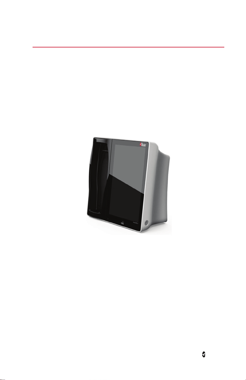
Root
Root displays parameters and trends that relate to regional oxygen saturation (rSO
2
).
For more information about Root, see Operator’s Manual for Root.
www.masimo.com 17 Masimo
Page 20
O3 Regional Oximeter Chapter 2: System Description
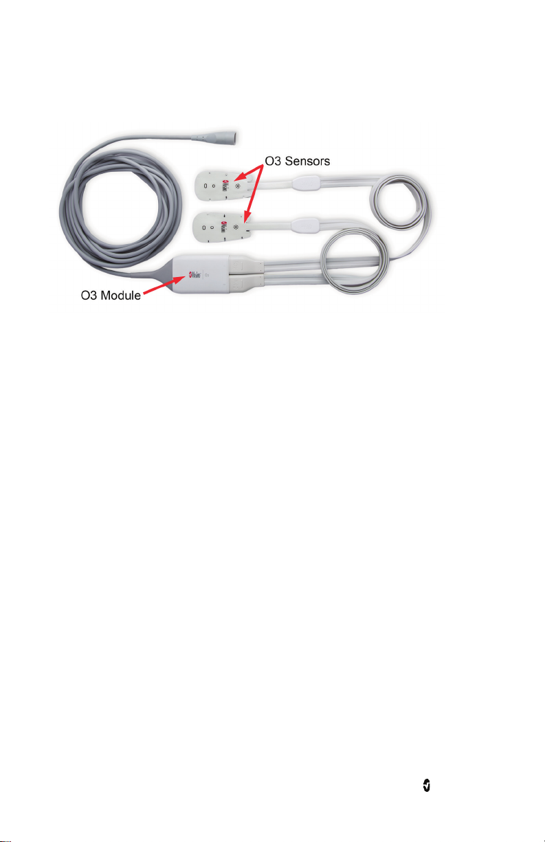
O3 Module and O3 Sensor
The O3 System consists of the O3 Module and O3 Sensors.
The O3 Sensors comprise of LED components that collect physiological signals. The O3
Module includes Masimo technology for processing the signals which result in rSO
measurements. In turn, these measurements are displayed on the Host/Backboard device.
The O3 Sensor is a single-patient use adhesive sensor, which comprises of a single emitter
and two detectors. For more information about the O3 Sensor, see Directions for Use for the
O3 Sensor.
The O3 cable connection for the sensor consists of two configurations. The difference
between the two configurations is that one version is a detached cable connection, where the
O3 sensor connects into the O3 module directly. In the other version, the connection is
integrated within the O3 module on one end and the other end has a connection for the O3
sensor(s).
2
www.masimo.com 18 Masimo
Page 21

Chapter 3: Setting Up the O3 System
For initial use of O3 System, the following setup instructions must be followed.
Unpacking and Inspecting the System
1. Remove the components from the shipping carton and examine them for signs of
shipping damage.
2. Check all materials against the packing list. Save all packing materials, invoice
and bill of lading. These may be required to process a claim with the carrier.
3. If anything is missing or damaged, contact the Masimo Technical Service
Preparation for Use
Prior to using the O3 System for monitoring
Department.
1. Confirm that you have all system components:
• Root
• O3 Module
• O3 Sensor(s)
2. Confirm that Root holds adequate battery power.
Connecting the O3 Module to Root
Up to two O3 Modules can be connected to Root.
To connect a Module to Root:
1. Identify the Masimo Open Connect (MOC-9
illustrated in the image below.
www.masimo.com 19 Masimo
TM
) connector on the O3 module, as
Page 22
O3 Regional Oximeter Chapter 3: Setting Up the O3 System
2. Insert the MOC-9 connector securely into a MOC-9 Port on Root, as illustrated in
the image below.
3. The module is now activated. This is verified when the O3 Module window displays
on Root with all parameters and measurements dashed out because no O3 Sensor
has been connected to the module.
For more information on the O3 Module window, see The O3 Module Window on page 25.
Repeat the steps above for the second module if more than two sensors are intended to be
used.
www.masimo.com 20 Masimo
Page 23
O3 Regional Oximeter Chapter 3: Setting Up the O3 System
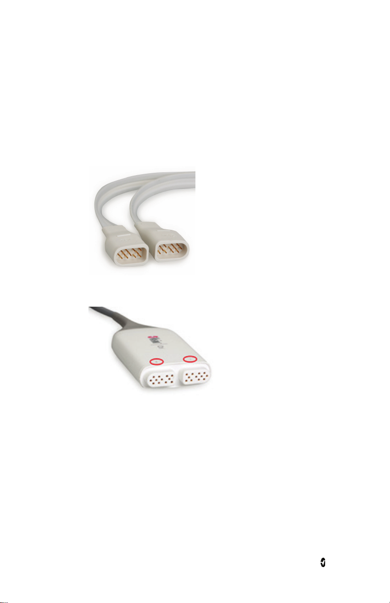
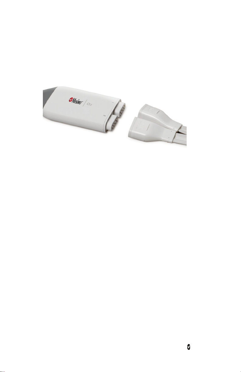
Connecting the O3 Sensor(s) to the O3 Module
Up to two (2) sensors can be connected to each O3 module. The two (2) connections are
symmetrical in orientation and clearly marked “1” and “2” on the module.
To connect an O3 Sensor to an activated O3 Module:
1. Apply sensor on the patient. For more instructions on applying the sensor on the
patient, see the Directions for Use for the O3 Sensor.
2. Once the sensor(s) has been properly applied on the patient, identify the
connector end on the sensor, illustrated in the image below.
3. Align the connector with the appropriate sensor connection on the module, as
illustrated in the image below. Note the markings of "1" and "2" above the
connections.
1 - Left Forehead
2 - Right Forehead
www.masimo.com 21 Masimo
Page 24
O3 Regional Oximeter Chapter 3: Setting Up the O3 System
4. Insert the connector securely into the sensor connection. Note that 1 is defaulted
to the left forehead and 2 is defaulted to the right forehead. The sensor site
selection can be modified by accessing the Site Selection menu. See The O3
Module Window on page 25 for information on how to access the Site Selection
menu.
5. Press the Home button on the touchscreen to return to the main display.
www.masimo.com 22 Masimo
Page 25

Chapter 4: Operation
The following sections describe how O3 Module information is displayed when used with
Root, including display details and user-configurable settings. For additional information on
Root, see Operator’s Manual for Root.
Regional Oxygenation Information
Regional Oxygenation (rSO2)
rSO2, measured in percentage (0 to 99%), is the regional tissue oxygenation level in the deep
tissue local to the sensor site.
AUC Index (Area under the Curve)
AUC, measured in % * minutes, is displayed as an index which quantifies the duration and
depth of patient’s stay below the user-defined rSO
refers to the amount of time the patient stays below the rSO
between the patient’s rSO
below the selected LAL.
level and the rSO2 LAL. AUC increases only when rSO2 level drops
2
Baseline
low alarm limit (LAL). Duration (minutes)
2
LAL. Depth (%) refers to the gap
2
This feature is displayed when Set Baseline has been enabled. To enable this option see
Baseline View on page 29 of the Operator's Manual.
Baseline rSO
triangular pointer on the y-axis of the trend display for rSO
Note: When the sensor is on the patient, the baseline rSO
value. When the sensor is not on the patient, the Baseline rSO2 value defaults to a minimum
displays the user-defined baseline value for rSO2. Baseline is also shown as a
2
.
2
value defaults to the current rSO
2
2
value of 10%.
Delta Baseline (Δbase)
This feature is displayed when Set Baseline has been enabled. To enable this option see
Baseline View on page 29.
Δbase, measured in percentage, is the relative decrease in rSO
www.masimo.com 23 Masimo
with respect to baseline rSO2.
2
Page 26

O3 Regional Oximeter Chapter 4: Operation
Delta SpO2 (ΔSpO2)
ΔSpO2, displayed as a percentage, is the calculated difference between rSO2 and SpO2.
Source of SpO2 is from peripheral SpO2 (using pulse oximeter, if available), depending on
user selection.
Peripheral SpO2 measurements are not provided by the O3 Module. The measurements are
provided by another device such as the Masimo pulse oximetry technology.
www.masimo.com 24 Masimo
Page 27

O3 Regional Oximeter Chapter 4: Operation
The O3 Module Window
When an O3 Module is connected to Root, O3 Module parameters and measurements display
in the O3 Module window as numeric values with graphical representations. Each O3 Sensor
connected will generate a separate O3 Module window, with the Sensor Label displayed in the
name of the window.
When multiple technologies are connected to Root, each technology’s parameters are
displayed in an individual window. The relative size of each window can be configured using
the Layout feature, which is accessible by pressing the Layout icon in the Main Menu. For
more information, see Operator's Manual for Root. In the image below, Radical-7 parameters
and measurements are displayed in the rainbow window; and O3 Module parameters and
measurements are displayed in a separate O3 Module window.
www.masimo.com 25 Masimo
Page 28

O3 Regional Oximeter Chapter 4: Operation
At the top-right corner of each O3 Module window, there is a drop-down menu which allows
you to display options and access the site selection and set baseline menus for each O3
Sensor.
Display Options
There are two display options available:
1. Trend View
2. Baseline View
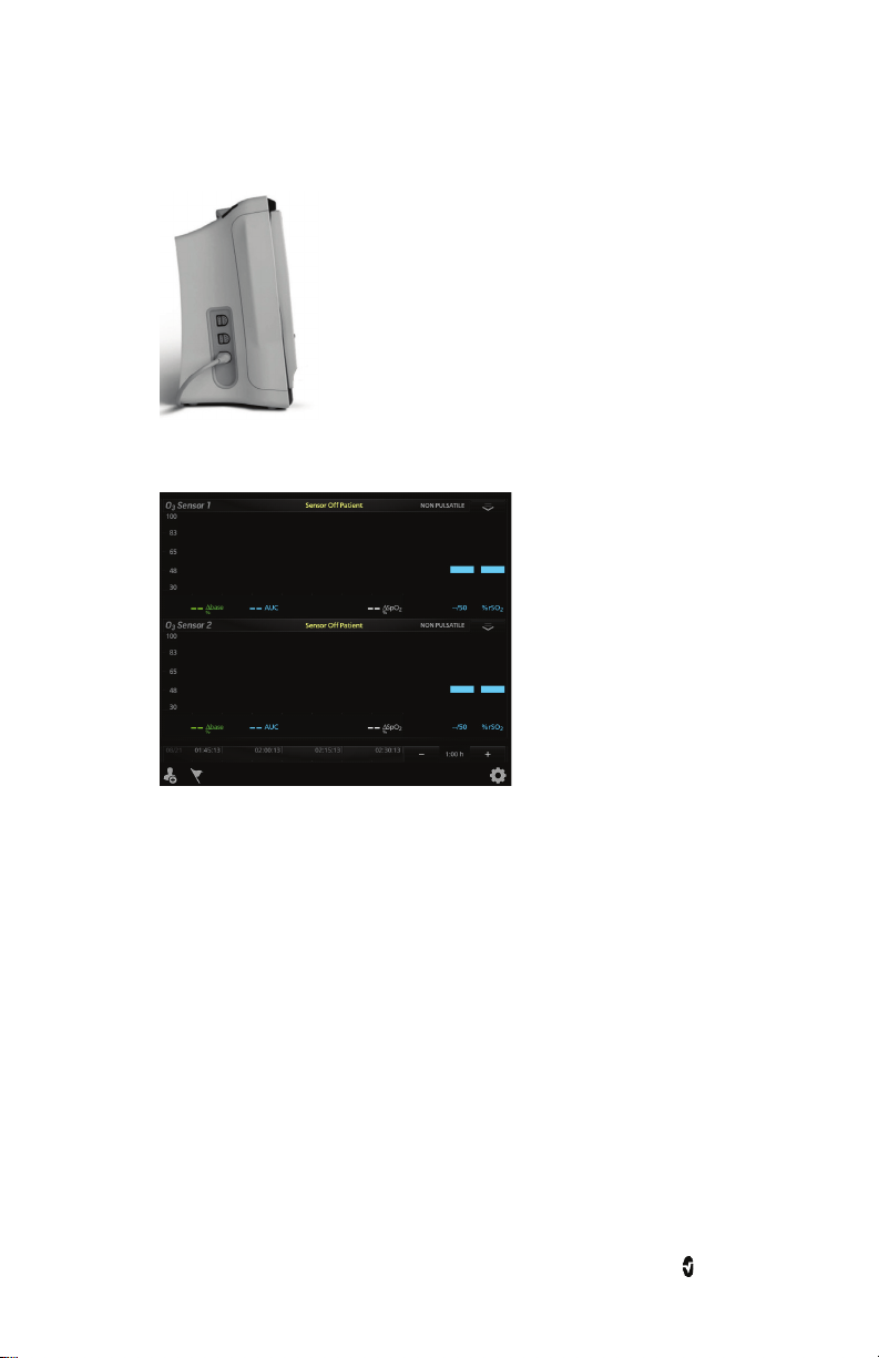
Trend View
Trend View is the default viewing option for an O3 window. The trend view displays rSO2
trends. This view offers two sensor displays for the two O3 Sensors that can connect to the
module, as illustrated in the image below. Note that each sensor display is distinguished by
the Sensor Label on the top left corner of each window.
To enable/disable Trend View, tap the drop-down menu on the top right corner of the O3
Module window. Press the Trend button to enable or disable Trend View.
www.masimo.com 26 Masimo
Page 29

O3 Regional Oximeter Chapter 4: Operation
Each sensor display shows a multitude of information about O3 Module parameters and
measurements and also allows the user to customize how the information is displayed. The
various portions of a sensor display are outlined in the illustration and each portion is
explained in more detail in the table below.
Ref. Feature Description
1 Sensor Label Label identifies the sensor site that corresponds to the application
site of the O3 Sensor.
2 SpO2 Trend Line Displays SpO2 level from the peripheral SpO2 sensor site over
3
ΔSpO2 Region
1
time
.
Displays the difference between levels of SpO2 (peripheral SpO2
sensor site) and rSO
of the O3 Sensor site over time.
2
4 rSO2 Trend Line Displays rSO2 level of the O3 Sensor site over time.
5 Drop-down Menu Allows user to change display options and access the site selection
and set baseline menus for each O3 Sensor.
6 rSO2 Value Indicates the current rSO2 level of the O3 Sensor site. Press the
value to access the rSO
menu.
2
7 %rSO2 Indicates the unit of measurement for rSO2 .
8 Time Frame Displays the current time frame of trending shown.
www.masimo.com 27 Masimo
Page 30

O3 Regional Oximeter Chapter 4: Operation
Configurator
Press “-” to shorten and “+” to lengthen the time frame of the
and selected
Ref. Feature Description
trending displayed.
9 rSO2 Alarm Limits Indicates the selected high and low limit values which triggers an
alarm. Press the value to access the rSO2 menu.
rSO
2
10
ΔSpO2%
Displays the difference between levels of SpO2 (peripheral SpO2
sensor site) and rSO
of the O3 Sensor site.
2
11 AUC Displays the Area Under the Curve cumulative index.
12 Timeline Displays timestamps and corresponding date.
13
Δbase%
Displays the current difference between levels of rSO2
baseline rSO2. Also displays the unit of measurement (%).
Press the value to access the Delta Baseline menu.
14 Y-axis Shows the current view range for rSO2. Press the axis to customize
the viewing range for rSO
.
2
15 Baseline Indicator Indicates the baseline rSO2 value selected by the user.
1
From the pulse oximetry sensor connected to the Radical-7® in the Root device.
www.masimo.com 28 Masimo
Page 31

O3 Regional Oximeter Chapter 4: Operation
Baseline View
In the Baseline view, the baseline rSO2 is seen as a horizontal yellow line across the entire
trend display. To enable/disable Baseline View, tap the drop-down menu on the top right
corner of the O3 Module window. Press the Baseline View button to enable or disable
Baseline View.
Ref. Feature Description
1 Baseline Indicator Indicates the baseline rSO2 value selected by the user.
2 Baseline Displays Baseline across the Trend area.
The Baseline View is displayed only when Set Baseline has been enabled. The Baseline can be
enabled in two ways:
1. Tap the drop-down menu on the top right corner of the O3 Module window. Press
the Set Baseline button to enable the baseline for the sensors.
Or
2. Press the Gear icon on the lower right corner of the main window of Root to access
the Main Menu, then press the O3 icon to access the O3 Module Menu and select
the Set Baseline menu. In the Set Baseline menu, select Enable. Press Ok to
confirm and press the Home button to return to the Main Window.
CAUTION: Reset Baseline for each new patient monitored, if applicable.
Note: Configuration for this option does not hold through power cycle.
www.masimo.com 29 Masimo
Page 32

O3 Regional Oximeter Chapter 4: Operation
Site Selection Menu
Note: The O3 system is intended for the monitoring of rSO2 in the cerebral region under the
sensors. Other Body Sensor Sites selections are for reference only and are not intended for
patient monitoring.
When the connector end on the O3 Sensor is first inserted into the O3 Module, 1 is defaulted
to the left forehead and 2 is defaulted to the right forehead. The sensor site selection can be
modified by accessing the Site Selection menu.
There are two ways to access this menu:
1. To access this menu tap the drop-down menu on the top right corner of the O3
Module window. Then press on the Site Selection button.
Or
2. Press the Gear icon on the lower right corner of the main window of Root to access
the Main Menu, then press the O3 icon to access the O3 Module Menu and select
the Site Selection Menu.
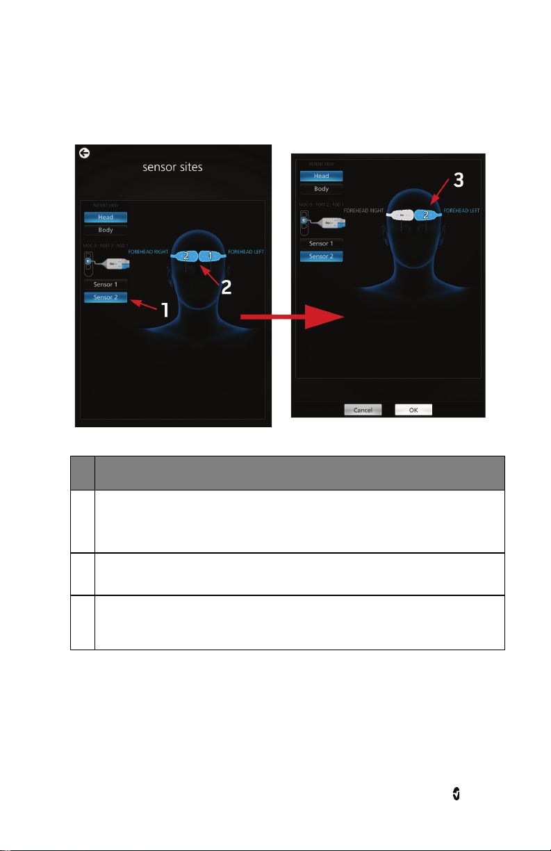
When the Site Selection menu is accessed, the sensor site screen displays on Root, as
illustrated below:
Select the Head or Body buttons at the upper left corner of the screen to switch between Head
and Body Patient View site selection menus.
Note: Sensor icons appear white when not selected and blue (with the corresponding sensor
number) when selected.
www.masimo.com 30 Masimo
Page 33
O3 Regional Oximeter Chapter 4: Operation
Head Patient View
Head is the default view when Site Selection is displayed.
Ref Description
1 Choose either sensor 1 then sensor 2 to change sensor site location. Only the selected
sensor location can be changed.
Note that 1 is defaulted to Forehead Left and 2 is defaulted to Forehead Right.
2 Touch the new desired sensor site location in the image. The sensor site can be on the
left, or right side of the body.
3 The new sensor site location will be displayed. Select OK to confirm the change. Repeat
this process for the corresponding sensor as necessary. Press the Home button to return
to the Main Screen.
www.masimo.com 31 Masimo
Page 34
O3 Regional Oximeter Chapter 4: Operation
The new sensor site location will be displayed. Select OK to confirm the change. Repeat
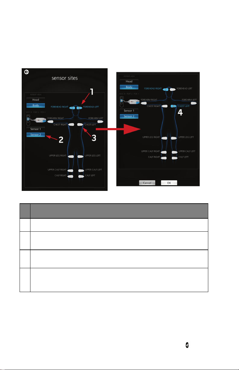
Body Sensor Sites
Select Body in the upper left corner of the screen to switch to the Body Sensor Sites locations
display.
Ref Description
1 Current location of sensor 1 and sensor 2 (Head).
2 Choose either the Sensor 1 or Sensor 2 button to select the sensor and change sensor
site location. Only the selected sensor can be changed.
3 Touch the new desired sensor site location in the image. The sensor site can be on the
left, or right side of the body.
4
this process for the corresponding sensor as necessary. Press the Home button to return
to the Main Screen.
www.masimo.com 32 Masimo
Page 35

O3 Regional Oximeter Chapter 4: Operation
Display and Alarm Settings
There are two ways to configure all parameter display and alarm settings:
1. Press the parameter icon in the O3 Module window of the specific sensor. This will
take you directly to the settings options for the parameter. Select the appropriate
setting and press Ok to confirm. Press the Home button to return to the main
screen.
Or
2. Press the Gear icon on the lower right corner of the main window to access the
Main Menu. Then press the O3 icon to access the O3 menu. In the O3 menu select
the POD icon to access the sensor menu. Press the appropriate O3 Sensor for
which to configure specific parameter display and alarm settings.
Below are the various setting options for each parameter.
Note: All setting options will hold through power cycle, unless otherwise stated.
rSO2 Settings
The following are the various setting options for rSO2:
About
An informational read-only screen appears with the following definition for rSO
rSO2, displayed as a percentage (0 to 99%), is the measure of regional tissue oxygenation (at
the deep tissue level) local to the sensor site.
Alarms
:
2
Option Description Factory
Default
High Limit Upper threshold of rSO2 level that
triggers an alarm.
Low Limit Lower threshold of rSO2 level that
triggers an alarm.
Configuration
Resolution
Options
Off
2% to 99%
Off
1%
40% 1% to 98% 1%
Duration of the temporary
Silence
Duration
suspension of audible alarm for rSO2
when the Alarm Silence icon is
2m
30s, 1m, 2m,
5m
N/A
pressed on Root.
www.masimo.com 33 Masimo
Page 36

O3 Regional Oximeter Chapter 4: Operation
Trend
Option Description Factory
Default
Y-Axis
Max
Y-Axis
Min
Maximum rSO2 level displayed in Trends
area.
Minimum rSO2 level displayed in Trends
area.
100% 5% to 100%
50% 0 to 95%
Configuration
Options
Additional Settings
Option Description Factory
Default
Averaging
Time
Length of time over which the system
calculates the average of all data points.
8s 8s, 16s, 24s
Configuration
Options
AUC Settings
The following are the various setting options for AUC:
About
An informational read-only screen appears with the following definition for AUC Settings:
Area Under the Curve (AUC) (%
depth of patient’s stay below the user-defined rSO
refers to the amount of time the patient stays below the rSO
between the patient’s rSO
below the selected LAL.
Additional Settings
minutes), displayed as an index, quantifies the duration and
*
level and the rSO2 LAL. AUC increases only when rSO2 level drops
2
low alarm limit (LAL). Duration (minutes)
2
LAL. Depth (%) refers to the gap
2
Option Description Factory Default Configuration Options
Reset AUC Resets the AUC Index
N/A Press Reset AUC to reset the value
www.masimo.com 34 Masimo
Page 37

O3 Regional Oximeter Chapter 4: Operation
Delta Baseline (Δbase) Settings
The following are the various setting options for Delta Baseline:
About
An informational read-only screen appears with the following definition for Delta Baseline
Settings:
Relative deficit below baseline displayed as a percentage of the baseline rSO
difference between the user defined baseline rSO
above the baseline, delta baseline will display as 0.
level and current rSO2 level. If rSO2 level is
2
Alarms
level, is the
2
Option Description Factory
Default
Delta
Limit
Threshold of Δbase that triggers an
alarm.
Off
Duration of the temporary suspension
Silence
Duration
of audible alarm for Δbase when the
Alarm Silence icon is pressed on
2m 30s, 1m, 2m N/A
Root.
Configuration
Options
Off
-1% to -99%
Resolution
-1%
www.masimo.com 35 Masimo
Page 38

O3 Regional Oximeter Chapter 4: Operation
Delta SpO2 (ΔSpO2) Settings
Below is the setting option for Delta SpO2:
About
An informational read-only screen appears with the following definition for ΔSpO2 Settings:
Delta SpO2 (ΔSpO2), displayed as a percentage, is the calculated difference between rSO
and SpO2. Source of SpO2 is from peripheral SpO2 (using pulse oximeter, if available).
Peripheral SpO2 measurements are not provided by the O3 Module. The measurements are
provided by another device such as the Masimo pulse oximetry technology.
Alarms
2
Option Description Configuration
Options
Delta
Source
The peripheral SpO2 is compared against rSO
the ΔSpO2 measurement.
to generate
2
Peripheral
www.masimo.com 36 Masimo
Page 39

Chapter 5: Errors and Alarms
Exception Messages
The table below lists the types of messages that can appear on Root when using O3 Module
and O3 Sensor.
Exception Message Indication
Regional Oximeter
Disconnected
No Cable Connected
Incompatible Cable The O3 Module connected to Root cannot be used with Root.
Defective Cable The O3 Module connected to Root is defective.
No Sensor Connected
Incompatible Sensor
Defective Sensor The O3 Sensor connected to the O3 Module is defective.
Sensor Initializing
Sensor Off Patient
Pulse Search The O3 Module is searching for pulse.
Interference Detected Signal interference to the O3 Module has been detected.
Low Perfusion Index The signal detected is too weak.
The O3 Module is not connected to Root or has been disconnected
from Root.
The O3 Module is not connected or not fully inserted into the MOC-9
Port.
The O3 Sensor is not connected or not fully inserted into the O3
Module, or the sensor is not applied on the patient.
The O3 Sensor connected to the O3 Module cannot be used with the
O3 Module.
The O3 Module is checking the connected O3 Sensor for proper
functioning and performance.
The O3 Sensor is not applied on the patient, the sensor is not
properly applied on the patient, or the Sensor is damaged.
Check Sensor
Connection
www.masimo.com 37 Masimo
The O3 Sensor may not be properly connected to the O3 Module.
Page 40

O3 Regional Oximeter Chapter 5: Errors and Alarms
Alarms Messages
The table below lists the types of alarms that can appear on Root when using O3 Module.
Alarm Message Indication
Low rSO2 rSO2 level is below low limit.
High rSO2 rSO2 level is above high limit.
Low Δbase
rSO2 level is less than the Delta Baseline low limit.
www.masimo.com 38 Masimo
Page 41

Chapter 6: Troubleshooting
To troubleshoot issues with Root, see the Operator's Manual for Root. To troubleshoot issues
with O3 Sensor, see the Directions for Use for the O3 Sensor. If a problem persists, contact an
Authorized Masimo Representative.
Troubleshooting O3 Module
Message
Displayed
Regional
Oximeter
Disconnected
No Sensor
Connected
Incompatible
Sensor
Possible Cause Action
O3 Module
disconnected from
Root.
O3 Sensor is not be
properly inserted
into O3 Module.
O3 Sensor may be
defective.
O3 Module may be
defective.
O3 Sensor is not
properly inserted
into O3 Module.
O3 Sensor may have
expired.
O3 Sensor may be
defective.
Plug in O3 Module to Root again.
Confirm that O3 Sensor is securely inserted into
O3 Module. For more information about
connecting O3 Sensor to O3 Module, see Chapter
3: Setting Up the O3 System on page 19 of the
Operator's Manual.
Replace O3 Sensor.
Replace O3 Module.
Confirm that O3 Sensor is securely inserted into
O3 Module. For more information about
connecting O3 Sensor to O3 Module, see Chapter
3: Setting Up the O3 System on page 19 of the
Operator's Manual.
Confirm the expiration date of the O3 Sensor has
not passed.
Replace O3 Sensor.
O3 Module may be
defective.
Defective Sensor O3 Sensor may be
Sensor Off
Patient
www.masimo.com 39 Masimo
defective.
O3 Sensor is not
properly applied on
the patient.
Replace O3 Module.
Replace O3 Sensor.
Confirm that O3 Sensor is properly applied on the
patient. For more information, see Directions for
Use for the O3 Sensor.
Page 42

O3 Regional Oximeter Chapter 6: Troubleshooting
Message
Displayed
Possible Cause Action
O3 Sensor may be
Replace O3 Sensor.
defective.
O3 Module may be
Replace O3 Module.
defective.
www.masimo.com 40 Masimo
Page 43

Chapter 7: Specifications
Display Ranges and Resolution
Parameter Range Resolution
rSO2 0 to 99% 1%
ΔSpO2
Δbase
0 to 99% 1%
0 to 99% 1%
Measurement Accuracy
Measurement [1] A
rSO2 (trending) [2] 3% (from 45% to 85% SavO2)
rSO2 (absolute) [3] 4% (from 45% to 85% SavO2)
* The A
distributed; approximately 68% of the measured values fell within +/- the A
Accuracy is calculated based upon measurement values that are statistically
RMS
compared to the reference device under a controlled study.
RMS
value when
RMS
www.masimo.com 41 Masimo
Page 44

O3 Regional Oximeter Chapter 7: Specifications
Environment
Module Operating Conditions
Item Description
Temperature at ambient humidity
32˚F to 104˚F (0˚C to 40˚C)
Operational Humidity 10% to 95%, non-condensing
Module Storage and Shipping Conditions
Item Description
Temperature at ambient humidity
-40˚F to 158˚F (-40˚C to 70˚C)
Storage humidity 10% to 95%, non-condensing
Altitude Up to 12,000 feet (3700 meters)
Physical Characteristics of the Module
Item Description
Width 2 inches (5.1 centimeters)
Length
12 inches (30.5 centimeters)
Cable portion: 12 feet (3.7 meters)
Thickness
Weight
1 inch max (2.5 centimeters)
7 oz. max (200 grams)
www.masimo.com 42 Masimo
Page 45

O3 Regional Oximeter Chapter 7: Specifications
Symbols
The following symbols are on the product hardware or packaging.
Symbol Description
Follow instructions for Use
Consult Instructions for Use
Separate collection for electronic waste
Mark of conformity to European Medical Device Directive 93/42/EEC
Federal law restricts this device to sale by or on the order of a licensed physician
Authorized Representative in the European Community
Storage/transport relative humidity range
Storage Temperature Range
Atmospheric Pressure Limitation
Keep dry
Fragile/breakable, handle with care
www.masimo.com 43 Masimo
Page 46

O3 Regional Oximeter Chapter 7: Specifications
Symbol Description
Caution
Date of Manufacture
Manufacturer
Non-sterile
Type BF Applied Part
IPX1 IPX1 Protection against liquid drops falling vertically
Catalog number (model number)
Serial Number
Instructions/Directions for Use/Manuals are available in electronic format
@http://www.Masimo.com/TechDocs
Note: eIFU is not available for CE mark countries.
www.masimo.com 44 Masimo
Page 47

O3 Regional Oximeter Chapter 7: Specifications
Guidance and Manufacturer's Declarations
Safety Classifications
1. Type of Protection against Electric Shock of the Module
Class II: Electrical equipment in which protection against electric shock does not
rely on BASIC INSULATION only, but in which additional safety precautions such
as DOUBLE INSULATION or REINFORCED INSULATION are provided, there being
no provision for protective earthing or reliance upon installation conditions.
2. Degree of Protection against Electric Shock of the Module with Sensor
An F-type applied part is isolated from all other parts of the equipment to such a
degree that the patient leakage current allowable in single fault condition is not
exceeded when a voltage equal to 1.1 times the highest rated AC supply voltage is
applied between the applied part and earth.
Root incorporates circuitry, creepage and clearance distances from the mains in
accordance with EN 60601-1. Root and the sensor provide patient isolation.
3. Degree of Protection against the Ingress of Liquid
Both Root and the Module have an ingress of liquid rating of IPX1 (drip proof).
4. Degree of safety of application in the presence of a flammable anesthetic
mixture with air or with oxygen or nitrous oxide
Equipment not suitable for use in the presence of a flammable anesthetic mixture
with air, or with oxygen or nitrous oxide.
5. Mode of Operation of O3 Module
Continuous: The O3 Module may be operated under normal load for an unlimited
period, without the specified limits of temperature being exceeded.
Safety Compliance
Safety Compliance
IEC 60601-1, 2nd Ed.
EN 60601-2, 2
nd
Ed.
IEC 60601-1, 3rd Ed.
EN/ISO 80601-2-61:2011
EMC Compliance
EMC Compliance
See Operator's Manual for Root.
www.masimo.com 45 Masimo
Page 48

O3 Regional Oximeter Chapter 7: Specifications
Citations
[1] The clinical study was done on healthy adult male and female subjects with light to dark skin
pigmentation. The trending and absolute rSO
range of 45% to 85% SavO2 against 30% arterial and 70% jugular venous blood oxygen
saturations, measured by a laboratory CO-Oximeter. The study confirms that the O3 System
measurements meet the requirements.
[2] Trending accuracy is the root mean square relative error. It is calculated by comparing a
series of samples to the gold standard and the accuracy refers to how the changes in a series of
samples “trend” with the gold standard. The gold standard used was the oxygen saturation
calculated from arterial and jugular venous blood gas analysis.
[3] Absolute accuracy is the root mean square error where error is the difference between
individual samples and a gold standard.
accuracies were determined by testing in the
2
www.masimo.com 46 Masimo
Page 49

Chapter 8: Service and Maintenance
Cleaning Procedure
Cleaning of the O3 Module should be performed at regular intervals or in accordance with
hospital, as well as local and governmental regulations.
See Safety Information, Warnings and Cautions on page 9.
O3 Module is a reusable instrument which is supplied non-sterile.
To clean the O3 Module
• The outer surface of the instrument can be cleaned with a soft cloth dampened
with a mild detergent and warm water solution.
• Do not allow liquids to enter the interior of the instrument.
• The outer surface of the instrument can also be wiped down using any of the
following solvents:
• Cidex Plus (3.4% glutaraldehyde)
• 10% bleach solution
General Maintenance for O3 Module
Safety tests and internal adjustments should be done by qualified personnel only. Safety
checks should be performed at regular intervals or in accordance with hospital, as well as
local and governmental regulations.
The following is a checklist for the general maintenance of the O3 Module:
• 70% isopropyl alcohol solution
• Visually inspect equipment for functional or structural damage, including poor
seals, cracks, damaged springs, etc.
• Visually inspect cables, connectors, and connector pins for signs of damage or
wear.
• Visually inspect product identification labels to ensure they are clear and legible.
Service Instructions
O3 Module has no customer serviceable parts. Attempting to service O3 Module will void the
warranty. Safety tests and internal adjustments should be done by qualified personnel only.
See Sales & End-User License Agreement on page 49.
To contact Masimo, see Contacting Masimo on page 49.
www.masimo.com 47 Masimo
Page 50

O3 Regional Oximeter Chapter 8: Service and Maintenance
Repair Policy
Masimo or an authorized Service Department must perform warranty repair and service. Do
not use malfunctioning equipment. Have the instrument repaired.
Please clean contaminated and/or dirty equipment before returning, following the cleaning
procedure described in Cleaning Procedure on page 47. Make sure the equipment is fully dry
before packing.
To return the O3 Module for service, please follow the Return Procedure on page 48.
Return Procedure
Clean contaminated/dirty equipment before returning, following instructions in Cleaning
Procedure section. Make sure the equipment is fully dry before packing. Call Masimo at
800-326-4890 and ask for Technical Support. Ask for an RMA number. Package the
equipment securely, in the original shipping container if possible, and enclose or include the
following information and items:
• A letter describing in detail any difficulties experienced with the O3 Module.
Include the RMA number in the letter.
• Warranty information, a copy of the invoice or other applicable documentation
must be included.
• Purchase order number to cover repair if the O3 Module is not under warranty, or
for tracking purposes if it is.
• Ship-to and bill-to information.
• Person (name, telephone/Telex/fax number, and country) to contact for any
questions about the repairs.
• A certificate stating the O3 Module has been decontaminated for bloodborne
pathogens.
• Return the O3 Module to the shipping address listed in the Contacting Masimo
section below.
www.masimo.com 48 Masimo
Page 51

O3 Regional Oximeter Chapter 8: Service and Maintenance
Contacting Masimo
To contact Masimo, refer to the following:
USA, Canada, and Asia
Europe All Other Locations
Pacific
Masimo Corporation
40 Parker
Irvine, California
92618
USA
Tel:+1 949 297 7000
Fax:+1 949 297 7001
Masimo
International Sàrl
Puits-Godet 10
2000 NeuchatelSwitzerland
Tel:+41 32 720 1111
Fax: +41 32 724
1448
Contact your local Masimo
Representative
Sales & End-User License Agreement
This document is a legal agreement between you (“purchaser”) and Masimo Corporation
(“Masimo”) for the purchase of this Product (“Product”) and a license in the included or
embedded Software (“Software”) except as otherwise expressly agreed in a separate contract
for the acquisition of this Product, the following terms are the entire agreement between the
parties regarding your purchase of this Product. If you do not agree to the terms of this
agreement, promptly return the entire Product, including all accessories, in their original
packages, with your sales receipt to Masimo for a full refund.
Warranty
Masimo warrants to the initial Purchaser for a period of one (1) year from the date of purchase
that: each new Product and the Software media as delivered are free from defects in
workmanship or materials. Masimo’s sole obligation under this warranty is to replace any
product that it deems to be covered under warranty with a replacement O3 Module.
Exclusions
The warranty does not extend to, and Masimo is not responsible for, repair, replacement, or
maintenance needed because of: a) modification of the Product or Software without Masimo’s
written authorization; b) supplies, instruments or electrical work external to the Product or
not manufactured by Masimo; c) disassembly or reassembly of the Product by anyone other
than an authorized Masimo agent; d) use of the Product with sensors or other accessories
other than those manufactured and distributed by Masimo; e) use of the Product and
Software in ways or in environments for which they are not labeled; and f) neglect, misuse,
improper operation, accident, fire, water, vandalism, weather, war, or any act of God. This
warranty does not extend to any product that has been used in violation of the operating
www.masimo.com 49 Masimo
Page 52

O3 Regional Oximeter Chapter 8: Service and Maintenance
instructions supplied with the product. This warranty does not extend to any Product that has
been reprocessed, reconditioned or recycled.
This warranty also does not apply to any Products provided to Purchaser for testing or
demonstration purposes, any temporary Products Modules or any Products for which Seller
does not otherwise receive a usage or purchase fee; all such Products are provided AS-IS
without warranty.
This warranty, together with any other express written warranty that may be issued by
Masimo is the sole and exclusive warranty as to the Product and Software. This warranty is
expressly in lieu of any oral or implied warranties, including without limitation any implied
warranty of merchantability or fitness for a particular purpose. Masimo shall not be liable for
any incidental, special or consequential loss, damage or expense directly or indirectly arising
from the use or loss of use of any Products or Software. In no event shall Masimo’s liability
arising from any Product and Software (under contract, warranty, tort, strict liability or other
claim) exceed the amount paid by purchaser for the Products giving rise to such claim. The
limitations in this section shall not be deemed to preclude any liability that cannot legally be
disclaimed by contract.
End-User License
1. Grant of License: In consideration of payment of the Software license fee, which is
part of the price paid for the Product, Masimo grants to Purchaser a nonexclusive,
nontransferable (except as set forth below) license (“License”), without right to
sublicense, to use the copy of the Software in connection with Purchaser’s use of
the Product for its labeled purpose as set forth in these directions for use. Masimo
reserves all rights not expressly granted to Purchaser.
2. Ownership of Software: The Software is licensed not sold; all rights and interests
in the Software and all copies thereof remain at all times vested in Masimo, and do
not pass to Purchaser. Any references in this Agreement to the purchase or sale of
the Software shall be deemed the purchase or sale of a Software License as set
forth herein.
Restrictions
1. Copyright Restrictions: The Software and the accompanying written materials are
copyrighted. Unauthorized copying of the Software, including Software that has
been modified, merged, or included with other software, or the written materials is
expressly forbidden. Purchaser may be held legally responsible for any copyright
infringement that is caused or incurred by Purchaser’s failure to abide by the terms
of this Agreement. Nothing in this License provides any rights beyond those
provided by 17 U.S.C. §117.
2. Use Restrictions: Purchaser may physically transfer the Product from one location
to another provided that the Software is not copied. Purchaser may not
electronically transfer the Software from the Product to any other device.
Purchaser may not disclose, publish, translate, release, distribute copies of, modify,
adapt, translate, reverse engineer, decompile, disassemble, or create derivative
works based on the Software or the written materials.
3. Transfer Restrictions: In no event may Purchaser transfer, assign, rent, lease, sell,
or otherwise dispose of the Product or the Software on a temporary basis.
Purchaser shall not assign or transfer this License, in whole or in part, by operation
of law or otherwise without Masimo’s prior written consent; except that the
Software and all of Purchaser’s rights hereunder shall transfer automatically to any
www.masimo.com 50 Masimo
Page 53

O3 Regional Oximeter Chapter 8: Service and Maintenance
party that legally acquires title to the Product with which this Software is included.
Any attempt to assign any rights, duties or obligations arising hereunder other
than as set forth in this paragraph shall be void.
4. U.S. Government Rights: If Purchaser is acquiring Software (including the related
documentation) on behalf of any part of the United States Government, the
following provisions apply: the Software and documentation are deemed to be
"commercial software" and "commercial computer software documentation,"
respectively pursuant to DFAR Section 227.7202 FAR 12.212, as applicable. Any
use, modification, reproduction, release, performance, display or disclosure of the
Software (including the related documentation) by the U.S. Government or any
of its agencies shall be governed solely by the terms of this Agreement and shall
be prohibited except to the extent expressly permitted by the terms of this
Agreement.
No Implied License
Possession or purchase of this device does not convey any express or implied license to use
the device with unauthorized sensors or cables that would, alone, or in combination with the
device, fall within the scope of one or more of the patents relating thereto. BY ACCEPTANCE
OR USE OF THIS DEVICE, YOU ACKNOWLEDGE YOUR ACCEPTANCE OF THESE TERMS.
www.masimo.com 51 Masimo
Page 54

Page 55

Index
A
About this Manual • 5
Alarms Messages • 38
AUC Index (Area under the Curve) • 23
AUC Settings • 34
B
Baseline • 23
Baseline View • 23, 29
Body Sensor Sites • 32
Connecting the O3 Sensor(s) to the O3
Module • 21
Contacting Masimo • 47, 49
Contraindication • 7
D
Delta Baseline (Δbase) • 23
Delta Baseline (Δbase) Settings • 35
Delta SpO2 (ΔSpO2) • 24
Delta SpO2 (ΔSpO2) Settings • 36
Display and Alarm Settings • 33
Display Options • 26
Display Ranges and Resolution • 41
C
Chapter 1
Technology • 13
Chapter 2
System Description • 17
Chapter 3
Setting Up the O3 System • 19, 39
Chapter 4
Operation • 23
Chapter 5
Errors and Alarms • 37
Chapter 6
Troubleshooting • 39
Chapter 7
Specifications • 41
Chapter 8
Service and Maintenance • 47
Citations • 46
Cleaning and Service Warnings and
Cautions • 12
Cleaning Procedure • 47, 48
Compliance Warnings and Cautions • 12
Components of the Regional Oximetry
System • 15
Connecting the O3 Module to Root • 19
E
EMC Compliance • 45
End-User License • 50
Environment • 42
Exception Messages • 37
Exclusions • 49
G
General Maintenance for O3 Module • 47
Guidance and Manufacturer's
Declarations • 45
H
Head Patient View • 31
I
Indications for Use • 7
M
Measurement Accuracy • 41
N
No Implied License • 51
www.masimo.com 53 Masimo
Page 56

O3 Regional Oximeter Index
O
O3 Module and O3 Sensor • 18
Overview • 13
P
Performance Warnings and Cautions • 10
Physical Characteristics of the Module •
42
Preparation for Use • 19
Principles of Beer-Lambert Law and
Regional Oximetry • 13
Product Description • 7
R
Regional Oxygenation (rSO2) • 23
Regional Oxygenation Information • 23
Repair Policy • 48
Restrictions • 50
Return Procedure • 48
Root • 17
rSO2 Settings • 33
U
Unpacking and Inspecting the System •
19
W
Warranty • 49
S
Safety Classifications • 45
Safety Compliance • 45
Safety Information, Warnings and
Cautions • 9, 47
Safety Warnings and Cautions • 9
Sales & End-User License Agreement •
47, 49
Service Instructions • 47
Site Selection Menu • 30
Symbols • 43
T
The O3 Module Window • 20, 22, 25
Trend View • 26
Troubleshooting O3 Module • 39
www.masimo.com 54 Masimo
Page 57

Page 58

www.masimo.com
38415/LAB-9358A 0616
 Loading...