

Page 1
GB - INSTALLATION MANUAL
IS 3.5
IS 4.0
IS 5.0
IS 6.0
masemase
masemase
mase
GENERATORS
Page 2

- 3 -
IS 3.5 - 4.0 - 5.0 - 6.0
THE GUARANTEE OF THE PRODUCT BECOMES
VOID IF THE SPECIFICATIONS CONTAINED IN THE
FOLLOWING INSTALLATION MANUAL ARE NOT
RESPECTED
E
1.1 Characteristics of the installation space ............. 5
1.2 Fastening the unit to the ground .........................5
1.3 Ventilation ..........................................................5
2.1. Sea water feed system ...................................... 5
2.2 Typical installation with electric generator
above the water-line ............................................9
2.3. Typical installation with electric generator
below the water-line ............................................ 9
2.4. Components .................................................... 11
2.5. Drainage system .............................................. 13
3.0 Fuel circuit ....................................................... 13
4.1. Battery connection ...........................................15
4.2. Control panel connection .................................. 15
4.3. A.C. Connection............................................... 17
4.4. Generator - Mains Switching ............................19
INSTALLATION1
2
COOLING WATER CIRCUIT
3
FUEL CIRCUIT
ELECTRICAL CONNECTION4
Page 3
IS 3.5 - 4.0 - 5.0 - 6.0
- 4 -
565
[22.24"]
675
[26.57"]
468
[18.43"]
Fig. 1
IS 3.5 - 4.0
IS 5.0 - 6.0
515
[20.28"]
590
[23.23"]
562
[22.13"]
342
[13.46"]
13
[0.51"]
13
[0.51"]
Ø
1
4
[
Ø
0
.
5
5
"
]
406
[15.98"]
1.0. INSTALLATION
1.1. Characteristics of the installation space
The generator must be installed in a sufficiently aired
space, supplying a little amount of air necessary for the
combustion of the motor.
The space must be separate and acoustically insulated
from living areas.
The generator should be positioned so that normal
maintenance operations can easily be carried out.
Propulsion motors are recommended for installation in the
area as long as they comply with the above-mentioned
conditions.
1.2. Fastening the unit to the ground
To fasten the unit securely, a base should be installed to
absorb vibrations and support the weight.
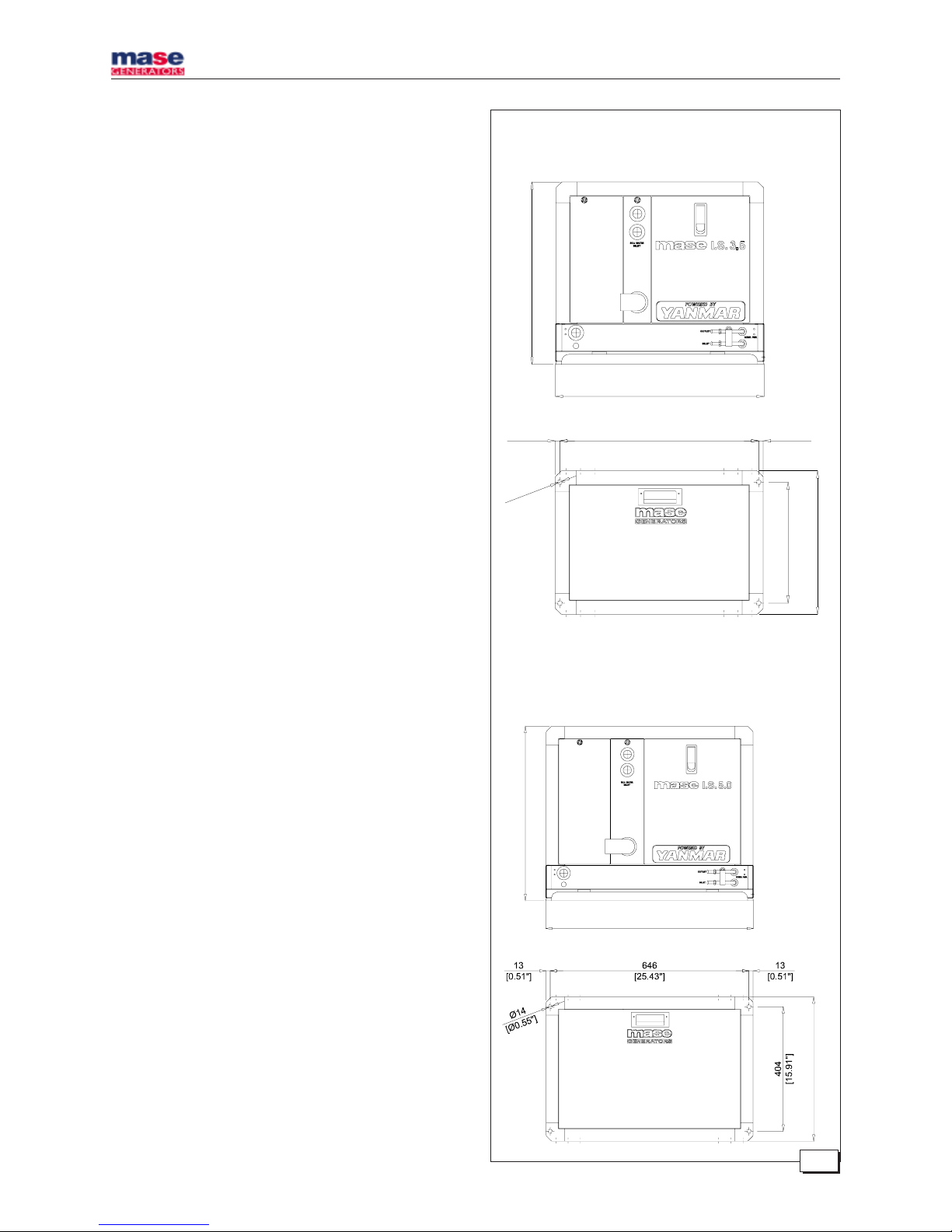
Drill holes in the base according to the instructions in
fig. 1.
1.3. Ventilation
The generator is equipped with an internal forced cooling
system through a water/air exchanger.
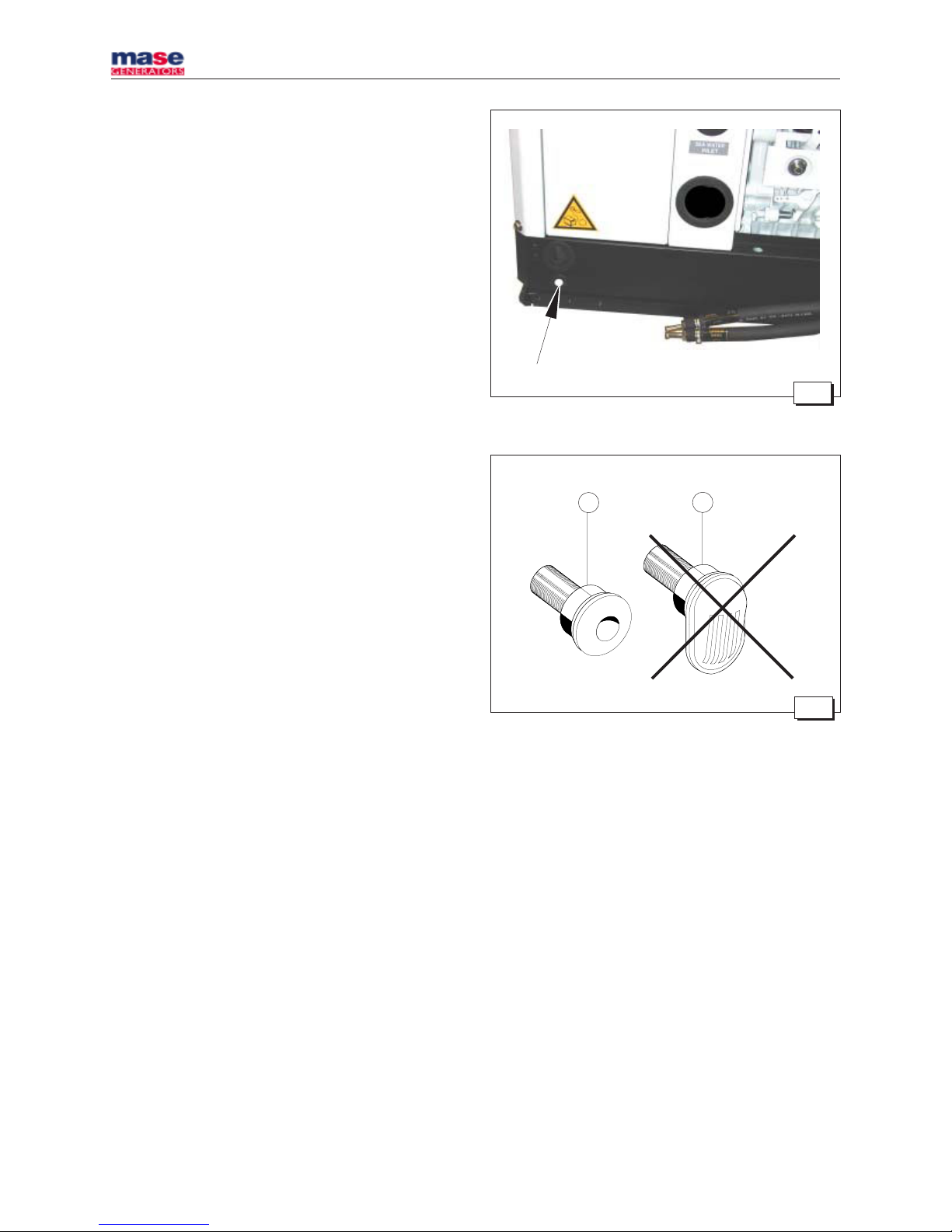
The air needed for combustion is taken in through the
opening on the base (fig. 2) so care must be taken to
ensure that this opening is always free.
2.0. COOLING WATER CIRCUIT
In electric generator , the motor is cooled by an opencircuit system in which sea water circulates.
The capacity of the sea water circuit is 1200 lt / h .
On installation a sea water feed circuit should be fitted for
cooling and a waste system to expel the mixture of flue
gas and water.
2.1. Sea water feed system
Boats usually use one of two systems to collect water
(fig. 3):
1 - Direct infeed system
2 - System with baffle
Page 4
IS 3.5 - 4.0 - 5.0 - 6.0
- 6 -
Fig. 2
1
2
Fig. 3
MASE recommend the direct infeed system ref. 1 fig. 3
since this system prevents water under pressure entering
the suction ducts and instead forms a pressure which can
easily be overcome by the water pump of the electric
generator.
IMPORTANT
Do not apply any type of protective hood to the
direct infeed system.
THE DIRECT INFEED SYSTEM SUPPLIED BY MASE
HAS BEEN MODIFIED TO PREVENT SOLID BODIES
ENTERING THE SYSTEM AND BLOCKING IT.
IF OTHER MATERIALS AVAILABLE ON THE MARKET
ARE USED, MORE CARE AND MORE FREQUENT
CLEANING IS NECESSARY.
The baffle system might cause the following problems:
a - If it is installed with the slots facing the prow.
In this case, during navigation and with the electric
generator off, pressure is accumulated in the water
infeed duct which might cause the system to fill up,
even as far as the exhaust port, allowing water to enter
the cylinders.
b - If it is installed with the slots facing the stern.
In this case a depression might accumulate in the
water infeed duct during navigation, preventing the
water pump from starting up the cooling plant, or
limiting the capacity and subsequently causing the
electric generator to overheat.
Page 5
- 9 -
IS 3.5 - 4.0 - 5.0 - 6.0
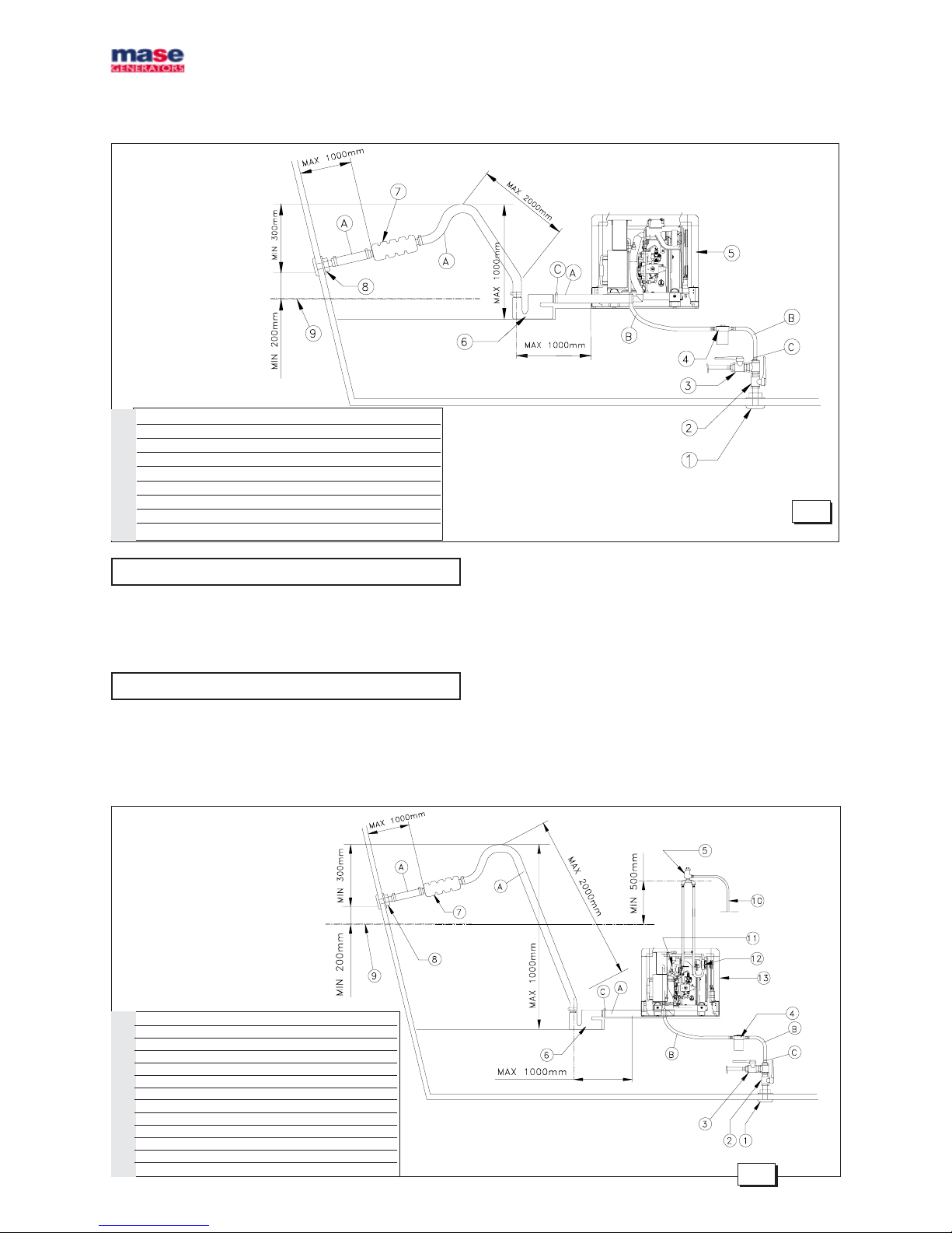
2.2. Typical installation with electric generator
above the water-line (fig. 4)
Fig. 4
1 Sea intake • Prise en mer
2 General tap-water • Robinet gènèral de l'eau
3 Tap to drain system • Robinet de vidage de l'installation
4 Water filter • Filtrè à eau
5 Electric generator • Groupe èletrogène
6 Muffler • Pot
7 Silencer • Silencieux
8 Sea drainage nozzle • Goult dècharge en mer
9 Water line • Ligne de flottaison
IMPORTANT
A - Tubes, internal diameter 45 mm
B - Tubes, internal diameter 15 mm
C - Clamps
CAUTION
The measurements shown in fig. 4-5 should
correspond exactly.
2.3. Typical installation with electric generator
below the water line (fig. 5)
1 Sea intake • Prise en mer
2 General tap-systemr • Robinet gènèral de l'eau
3 Tap to drain system • Robinet de vidage de l'installation
4 Water filter • Filtrè à eau
5 Anti-siphon valve • Soupape antisiphon
6 Muffler • Pot
7 Silencer • Silencieux
8 Sea drainage nozzle • Goult dècharge en mer
9 Water line • Ligne de flottaison
10 Drainage • Drainage
11 Drain mixer • Mèlangeur de purge
12 Water pump • Pompe à eau
13 Electric generator • Goupe èletrogène
Fig. 5
Page 6
IS 3.5 - 4.0 - 5.0 - 6.0
- 10 -
1
Fig. 6
Fig. 7
Fig. 8
Anti-siphon valve
Exhauste manifold
Water pump
Fig. 9
ANTI-SIPHON VALVE
2.4. Components
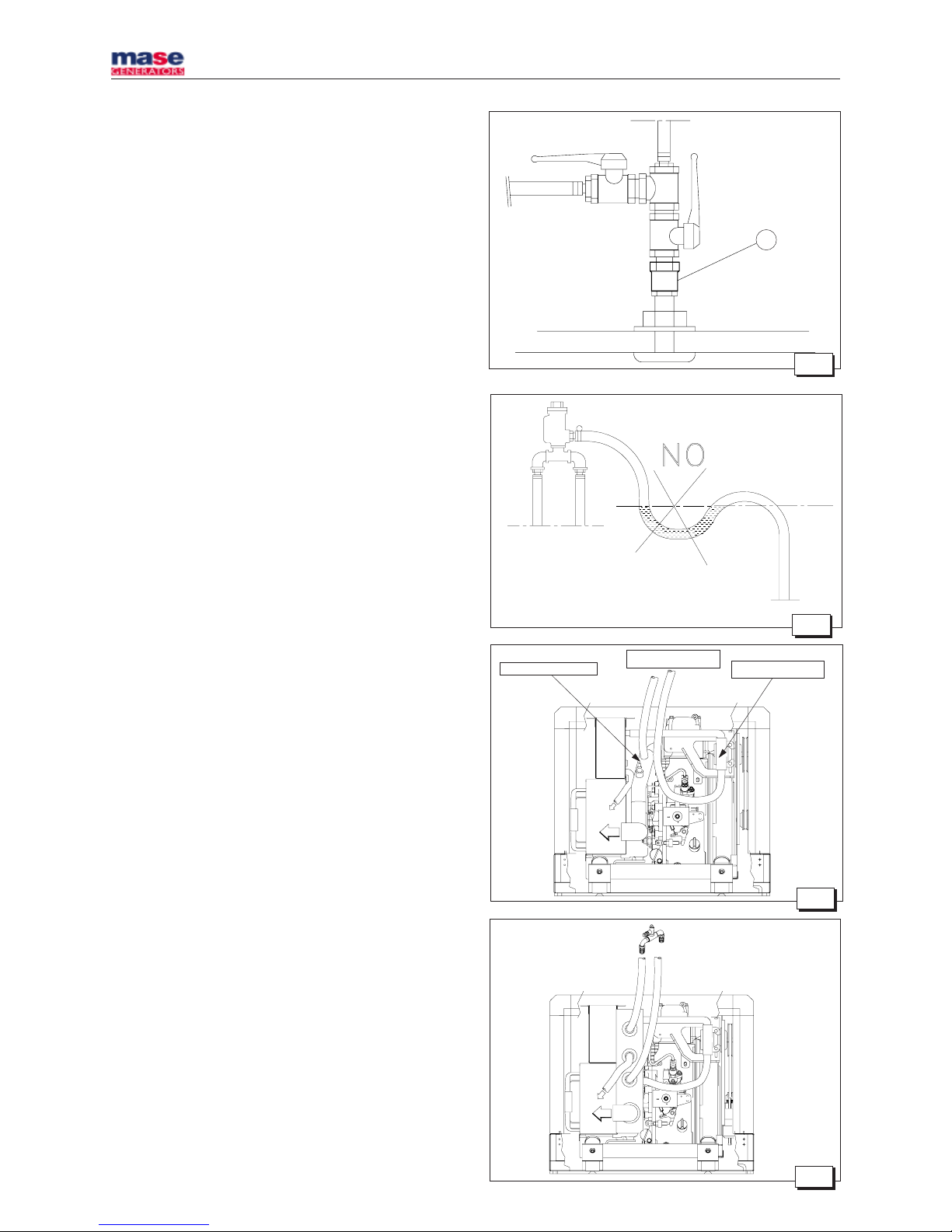
1 - Direct sea intake 1/2"
IMPORTANT
If the unit is installed more than 1 metre above the
water-line, a check valve should be fitted after the
sea intake (fig. 6, ref. 1) to prevent the water circuit
emptying when the motor is off. If this empties, the
rotor of the water pump might be damaged during
start up; for the same reason, when the unit is first
started up, the suction tube from the valve to the
pump should be filled manually.
2 - Ball tap (general) 1/2"
3 - Ball tap (drainage) 1/2"
This is used to drain the cooling system of the electric
generator for general maintenance or when a long
period of inactivity is expected.
4 - Water filter (can be inspected)
This must provide efficient protection for the cooling
circuit from the entrance of mud, sand and seaweed.
IMPORTANT
The filter mesh should be very fine. Mesh 2 - 470
micron is recommended, other sizes do not give
good filter performance.
5 - Anti-siphon valve: this valve returns the cooling circuit
to atmospheric pressure when the motor is switched
off, to prevent the siphon phenomenon.
It must be installed when the generator is fitted
with the drainage mixer on or beneath the water
line, and should be positioned at least 50 cm above
water level.(see fig. 8/9)
IMPORTANT
The drainage duct of the anti-siphon valve must
run beneath the valve itself in order to prevent
water accumulating in the duct, which should
always remain empty to allow air to pass through
when the unit is switched off. (see fig. 7)
N.B.: The drainage duct should be taken into the bilge
because during normal operation small quantities of water
might be leaked from the duct.
The box already includes 2 holes to connect the anti-siphon
valve (fig. 9).
Page 7
IS 3.5 - 4.0 - 5.0 - 6.0
- 12 -
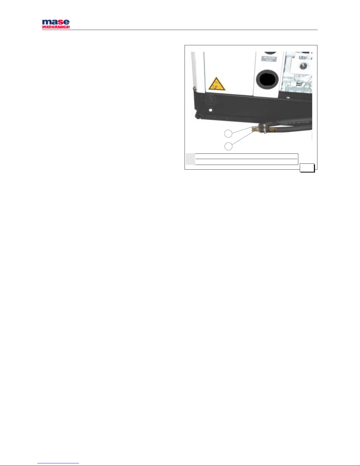
1 Diesel return
2 Diesel
Fig. 10
1
2
Page 8
IS 3.5 - 4.0 - 5.0 - 6.0
- 14 -
1
Fig. 13
Fig. 12
Fig. 11
3
+
2
4.0. ELECTRICAL CONNECTIONS
4.1. Battery connection
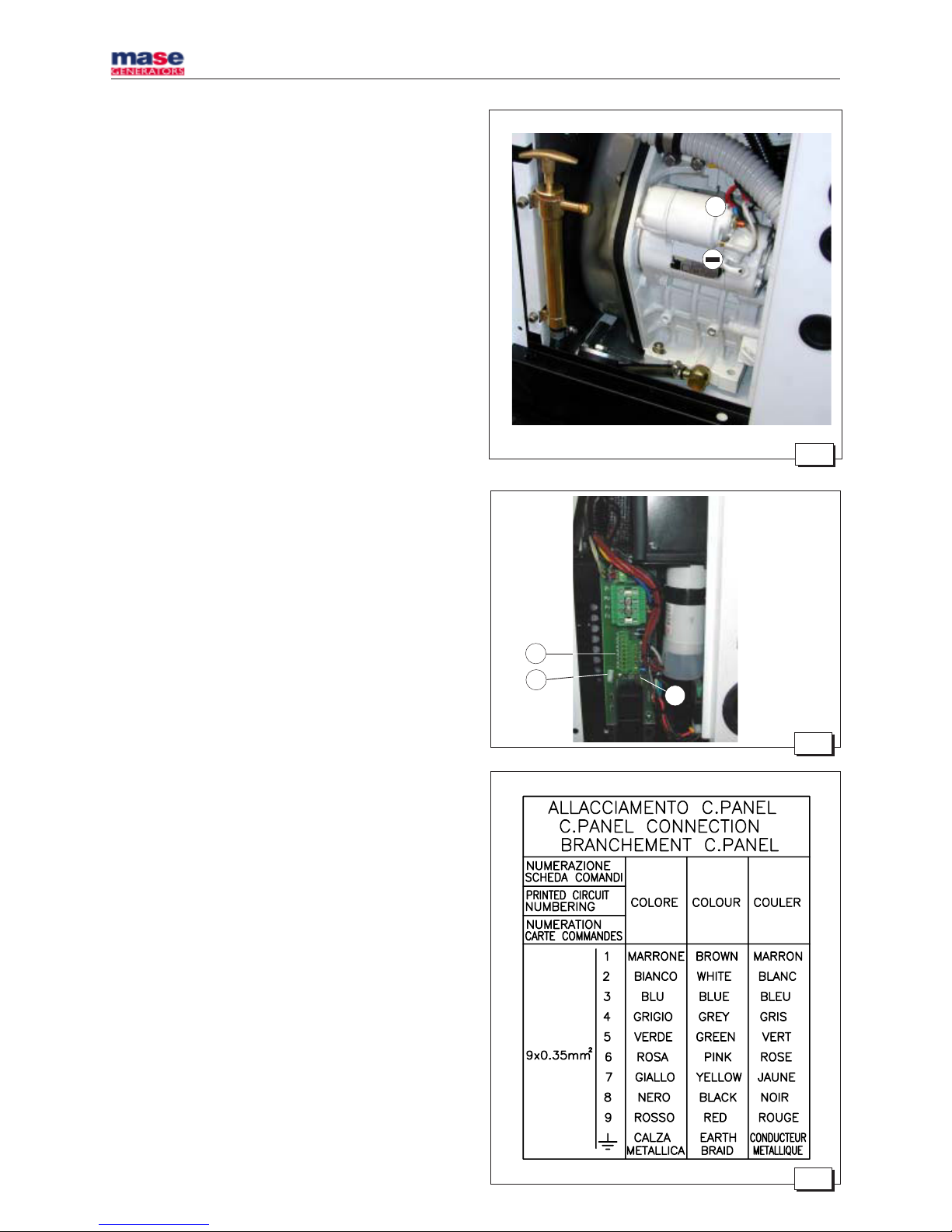
To start off the unit an independent battery of 12V is
needed, capacity 18 - 30 Ah min.
It should be connected to the clamp of the generator as
shown in fig. 11 with cables of section 25 mm2 up to
distances of 5 metres and with cables of section 35 mm
2
for longer distances, and following the sequence of
operations described below:
- First connect the positive pole (+) of the battery to the
terminal marked with the symbol (+) on the generator,
(the starter).
- Then connect the negative pole (-) of the battery to the
terminal marked with the symbol (-) on the generator.
- Wipe the connections with special mineral grease to
protect against oxidation and corrosion.
The generator includes an electronic device to
automatically recharge the start-up battery, giving 10
A, at a voltage of 12 V, when fully charged.
IMPORTANT
Install the battery in a well-ventilated area, away
from the generator and from any device which
might produce heat or sparks.
Periodically check the state of the connections of
the terminals and the water level of the battery. If the
cables need to be disconnected, follow the
instructions for connection in reverse order.
Do not invert the poles of the connecting cables
since serious damage might be caused to the
generator and the battery.
Do not connect other loads to the battery.
In order to reduce galvanic currents to a minimum, the () of the battery of the electric generator should not be
connected to the (-) of the other batteries on board.
4.2. Control panel connection
This connection can be made through the terminal boards
(fig. 12, ref. 1) using the cables provided already connected
to the control panel. The terminals to be used are those
marked no. 1 to no. 9 for the control cables. The earths
braid should be connected to the faston terminal (fig. 12,
ref. 2) insulating them carefully and using a pre-insulated
female faston. In making the connections it is important
to follow the diagram and the colours codes as indicate
(fig. 13). Fasten the cable with the provided plastic
support on the bail (fig. 12, ref. 3).
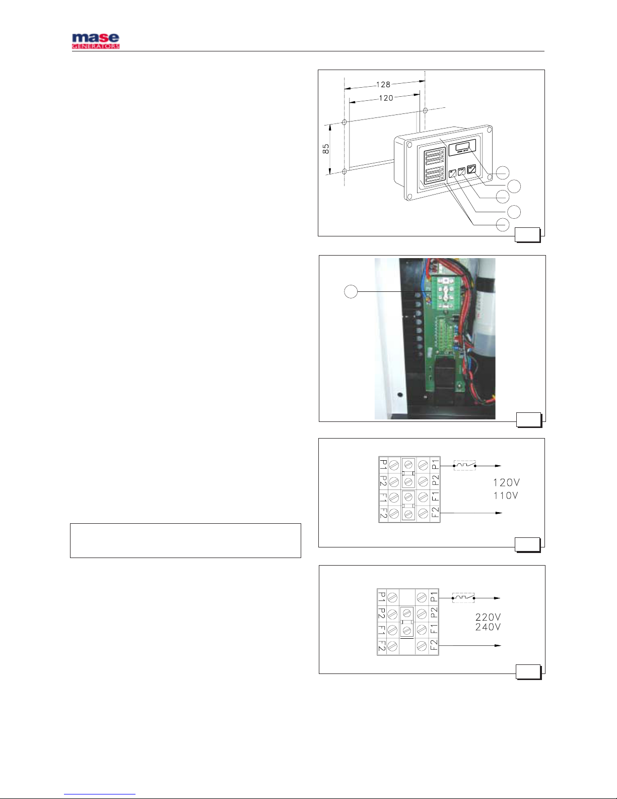
The control panel contains 5 LEDs for operation and alarm
(fig. 14, ref. 1), an hour counter (fig. 14, ref. 2) and the start
and stop buttons (fig. 14, ref. 3/4/5).
For fixing the control panel is necessary to perforate as
shown in fig.14.
Page 9

- 15 -
IS 3.5 - 4.0 - 5.0 - 6.0
4.0. ELECTRICAL CONNECTIONS
4.1. Battery connection
To start off the unit an independent battery of 12V is
needed, capacity 18 - 30 Ah min.
It should be connected to the clamp of the generator as
shown in fig. 11 with cables of section 25 mm2 up to
distances of 5 metres and with cables of section 35 mm
2
for longer distances, and following the sequence of
operations described below:
- First connect the positive pole (+) of the battery to the
terminal marked with the symbol (+) on the generator,
(the starter).
- Then connect the negative pole (-) of the battery to the
terminal marked with the symbol (-) on the generator.
- Wipe the connections with special mineral grease to
protect against oxidation and corrosion.
The generator includes an electronic device to
automatically recharge the start-up battery, giving 10
A, at a voltage of 12 V, when fully charged.
IMPORTANT
Install the battery in a well-ventilated area, away
from the generator and from any device which
might produce heat or sparks.
Periodically check the state of the connections of
the terminals and the water level of the battery. If the
cables need to be disconnected, follow the
instructions for connection in reverse order.
Do not invert the poles of the connecting cables
since serious damage might be caused to the
generator and the battery.
Do not connect other loads to the battery.
In order to reduce galvanic currents to a minimum, the () of the battery of the electric generator should not be
connected to the (-) of the other batteries on board.
4.2. Control panel connection
This connection can be made through the terminal boards
(fig. 12, ref. 1) using the cables provided already connected
to the control panel. The terminals to be used are those
marked no. 1 to no. 9 for the control cables. The earths
braid should be connected to the faston terminal (fig. 12,
ref. 2) insulating them carefully and using a pre-insulated
female faston. In making the connections it is important
to follow the diagram and the colours codes as indicate
(fig. 13). Fasten the cable with the provided plastic
support on the bail (fig. 12, ref. 3).
The control panel contains 5 LEDs for operation and alarm
(fig. 14, ref. 1), an hour counter (fig. 14, ref. 2) and the start
and stop buttons (fig. 14, ref. 3/4/5).
For fixing the control panel is necessary to perforate as
shown in fig.14.
Page 10
IS 3.5 - 4.0 - 5.0 - 6.0
- 16 -
1
3
4
5
2
Fig. 14
Fig. 15
Fig. 17
Fig. 16
1
IMPORTANT
The control panel is indispensable for operating the
unit and must be installed; do not use devices othet
than the control panel supplied with the unit since
they might not be compatible with the generator.
Make the connections with the battery disconnected.
CAUTION
The control panel is provided with a connecting
cable 10 metres long. This cable should not be
modified since it might cause the panel circuit to
function incorrectly.
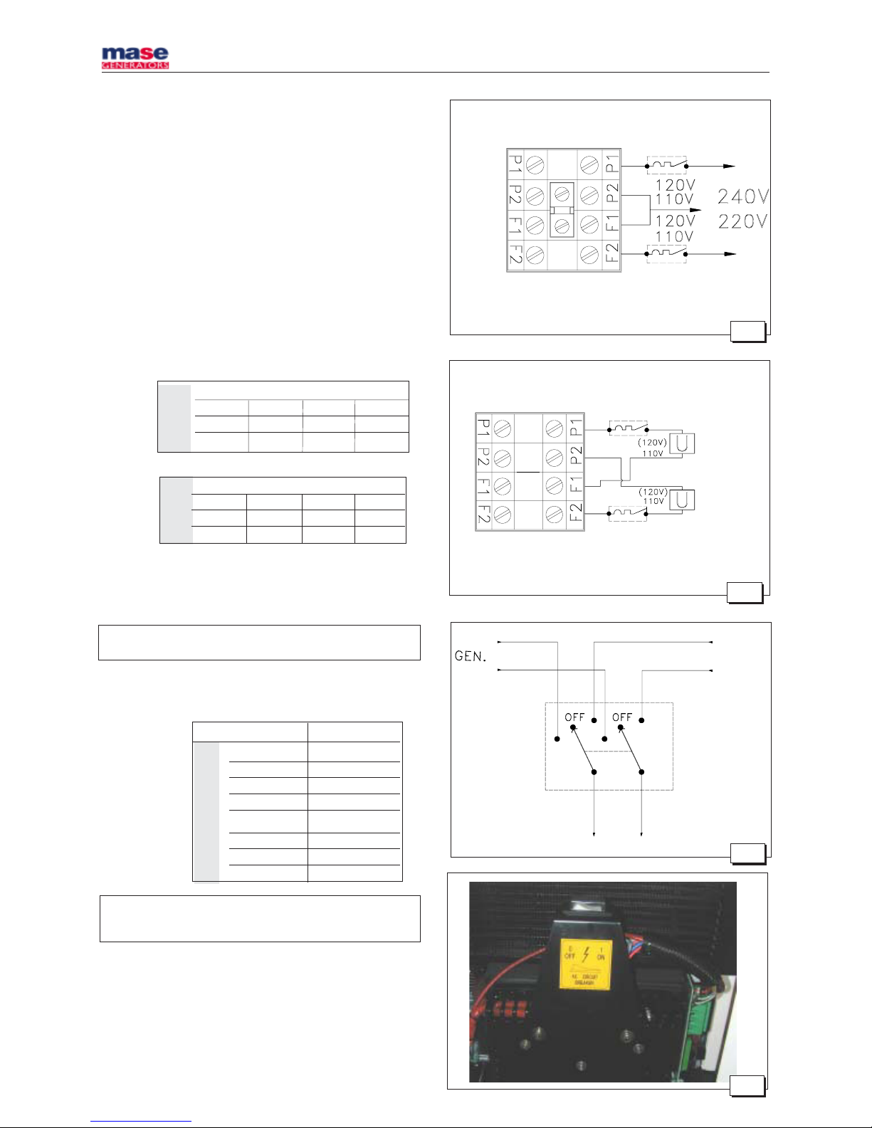
4.3. A.C. Connection
This connection can be done through the power terminal
board (fig. 15, ref. 1) placed inside the derivation box.
This range includes the possibility of use both at 110V
50Hz - 120V 60Hz and 220V 50Hz - 240V 60Hz.
For this reason it is possible to make two types of
connection (and use), according to the following
configurations.
1 - Parallel configuration: in this configuration there is a
single output at 110 (120) V between points P
1
and F2,
connecting the outputs of the alternator (P1, F1, P2, F2)
as shown in the diagram in fig. 16.
2 - Serial connection; in this configuration it is possible
to use a voltage of 220 (240) V between points P1 and
F2, as shown in the diagram in fig. 17.
In serial connection, power can be picked up both at 110
(120) V between points F1 - F2 and P1 - P2 and at 220 (240)
V between points P1 and F2 at the same time, as shown
in the diagram in fig. 18.
It is also possible to feed two separate lines as shown in
fig. 19 on the outputs P1- F1 and P2- F2.
N.B. In this case the power which can be taken from each of
the two outputs is half the rated nominal power.
Page 11
IS 3.5 - 4.0 - 5.0 - 6.0
- 18 -
Fig. 18
Fig. 19
CARICO
LOAD
CHARGE
CARICO
LOAD
CHARGE
RETE
MAINS
RESEAU
CARICO
LOAD
CHARGE
Fig. 20
Hz 50 50
V 110/220 110/220
W 2700 4000
A 12.3 18
IS 3.5 IS 5.0 - 6.0
Hz 60 60
V 120/240 120/240
W 2900 4800
A 12.1 20
IS 5.0 - 6.0
IS 3.5
Hz 50 60 50 60
V 110 120 220 240
W. 2700 2900 2700 2900
A 24.5 24.2 12.3 12.1
TAB 1
Hz 50 60 50 60
V 110 120 220 240
W. 4000 4800 4000 4800
A 36.5 40 18 20
Fig. 21
- Ensure that the sum of the loads to be supplied does not
exceed the nominal power of the electric generator.
- Magnetothermic protective devices or similar should be
placed between the generator and electrical equipment,
according to the tables shown below.
- To make both parallel and serial connections, use the
special bridges provided in the accessories to the
electric generator on the terminal board fig. 15 ref. 1.
Single voltage distribution
.
N.B: In these cases just one magnetothermic device should be
installed, see fig. 16/17.
Double voltage distribution
N.B: In these cases two magnetothermic devices should be installed,
see fig. 18/19, dimensioned on the current values (A) shown in
Table. 2.
4.4. Generator - Mains switching
A switch should be placed on the line to switch the user
appliances from the generator to an external power line.
The switch should be dimensioned according to the size
of the loads: a general diagram is shown in fig. 20.
 Loading...