

Page 1
© Marzocchi Suspension
2005 - 888 VF
2005 - 888 VF
Technical instructions
Page 2
© Marzocchi Suspension
2005 - 888 VF
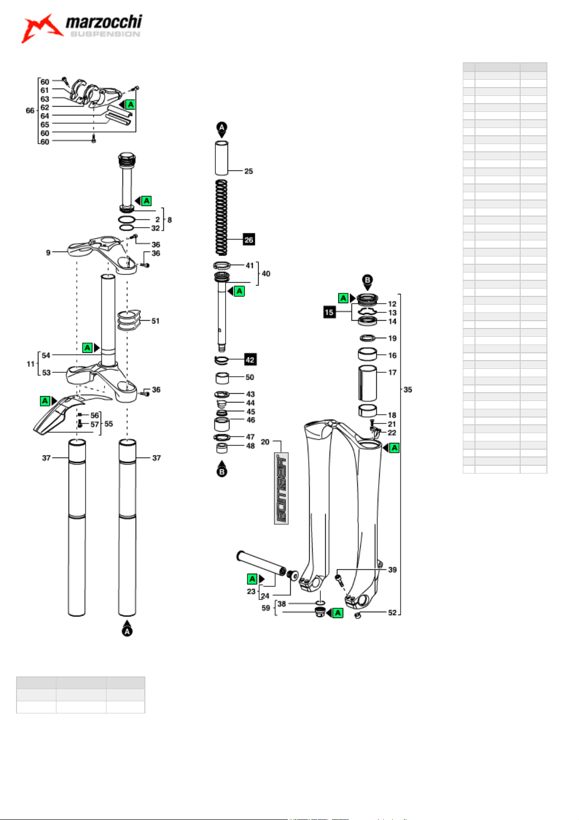
Exploded view - 888 VF 170
Rif. Code Quantity
2 528154 2
8 810060/R 2
9 501510LA 1
11 7051171/R 1
12 533167 2
13 523236 2
14 528034>B 2
16 538038>A 2
17 529194 2
18 538124 2
19 522406 2
20 547624 1
21 520341 1
22 5321153>A 1
23 850956/C 1
24 520349LA 1
25 5181299 2
26 5141293/C 1
32 528260 2
35 5321193RS/R> A 1
35 5321193RR/R >A 1
36 520344PN 7
37 507665/C 2
38 528051 2
39 520178PN 4
40 8031212/C 2
41 524180 2
42 5141294/C 1
43 522415 2
44 5141303 2
45 516107 2
46 509135 2
47 523078 2
48 512101 2
50 5181304 2
51 531072 2
52 526145AA 4
53 502559LA 1
54 508998CD/C 1
55 850760/C 1
56 526143RX 2
57 520342AR 2
59 5321199 2
60 520178PN 7
61 505084LA 1
62 505085LA 1
63 505083LA 1
64 526157KR 1
65 526158KR 1
66 850881/C 1
888 VF 170 - Oil levels
Position Oil type Quantity (cc)
Right fork leg SAE 7,5 - 550013 220
Left fork leg SAE 7,5 - 550013 220
Page 3

© Marzocchi Suspension
2005 - 888 VF
Spare part list - 888 VF 170
Rif. Code Description
2 528154 O-RING 2
8 810060/R PRELOAD PLUG UNIT 888VF 05 2
9 501510LA UPPER CROWN- 888 04 1
11 7051171/R
(replaces 7051171)
12 533167 DUST SEAL DIA.35 2
13 523236 STOP RING 2
14 528034>B OIL SEAL DIA.35 2
16 538038>A UPPER BUSHING DIA.35 2
17 529194 SLEEVE 2
18 538124 LOWER BUSHING 2
19 522406 WASHER 2
20 547624 RH+LH LABELS 888 VF 2005 1
21 520341 SCREW 1
22 5321153>A CABLE GUIDE 1
23 850956/C
(replaces R5127LA)
24 520349LA AXLE SCREW -QR 20 1
25 5181299 PRELOAD SLEEVE 2
26 5141293/C SPRINGS KIT K=3.2 1
32 528260 O-RING 2
35 5321193RS/R>A MONOLITE D.35- GLOSS ECO BLACK 1
35 5321193RR/R>A MONOLITE D.35-FLAT BLACK 1
36 520344PN SCREW 7
37 507665/C 888 STANCHION 2
38 528051 O-RING 2
39 520178PN SCREW 4
40 8031212/C PUMPING ROD 888 RT '04 2
41 524180 PISTON RING DIA.35 2
42 5141294/C REBOUND SPRINGS KIT K=2.5 1
43 522415 WASHER 2
44 5141303 SPRING 2
45 516107 VALVE 20,3 DIA.35 2
46 509135 FERRULE 2
47 523078 STOP RING 2
48 512101 FOOT BUFFER 2
50 5181304 SLEEVE 30MM 2
51 531072 RUBBER 2
52 526145AA BUSHING 4
53 502559LA LOWER CROWN 888-04 1
54 508998CD/C STEEL STEM 1
55 850760/C FENDER UNIT 1
56 526143RX FENDER BUSHINGS 2
57 520342AR FENDER SCREW 2
59 5321199 FOOT NUT UNIT 2
60 520178PN SCREW 7
61 505084LA RH CLAMP -888 1
62 505085LA LH CLAMP -888 1
LOWER CROWN+STEEL STEM 888 '04 1
AXLE+SCREW KIT-66/888 1
Q.ty in the
model
Page 4

63 505083LA LOWER HANDLEBAR CLAMP- 888 1
64 526157KR BUSHING 1
65 526158KR BUSHING 1
66 850881/C HANDLEBAR CLAMP KIT - 888 '04 1
© Marzocchi Suspension
2005 - 888 VF
Page 5
© Marzocchi Suspension
2005 - 888 VF
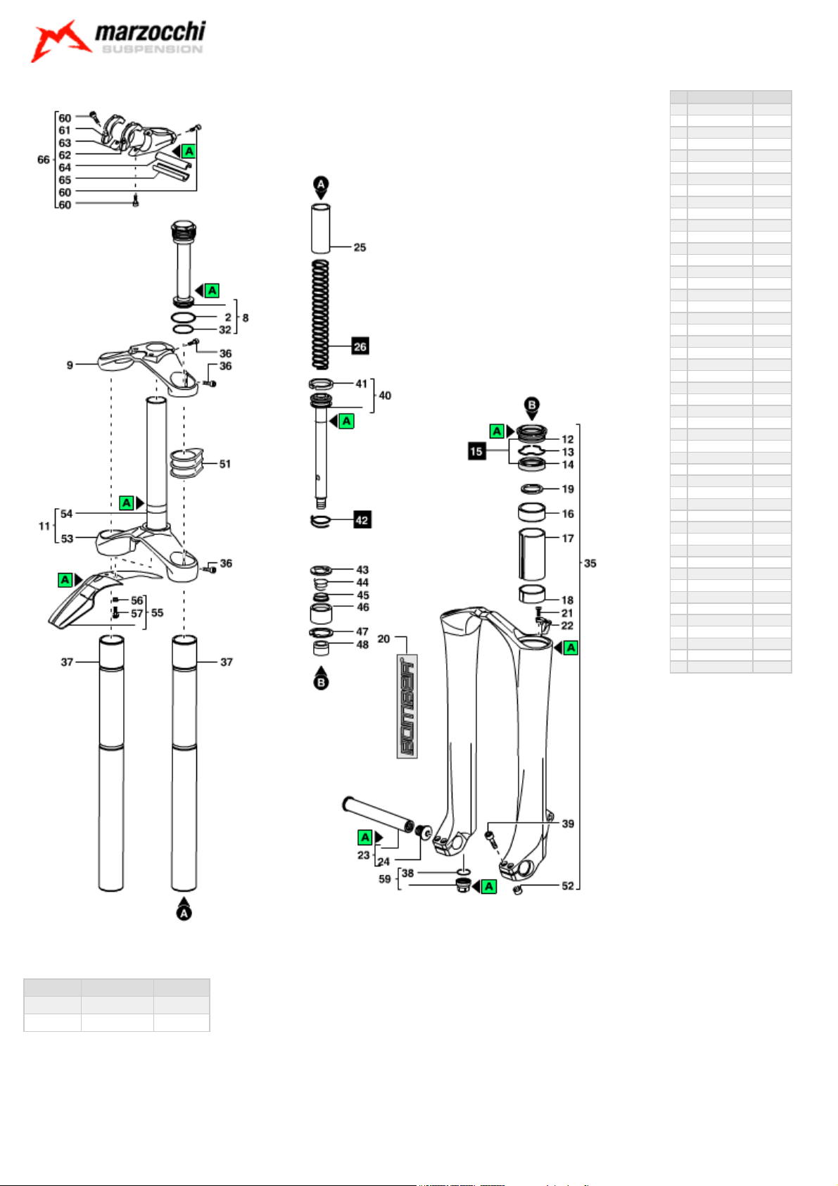
Exploded view - 888 VF 200
Rif. Code Quantity
2 528154 2
8 810060/R 2
9 501510LA 1
11 7051171/R 1
12 533167 2
13 523236 2
14 528034>B 2
16 538038>A 2
17 529194 2
18 538124 2
19 522406 2
20 547624 1
21 520341 1
22 5321153>A 1
23 850956/C 1
24 520349LA 1
25 5181253 2
26 5141293/C 1
32 528260 2
35 5321193RS/R> A 1
35 5321193RR/R >A 1
36 520344PN 7
37 507665/C 2
38 528051 2
39 520178PN 4
40 8031212/C 2
41 524180 2
42 5141294/C 1
43 522415 2
44 5141303 2
45 516107 2
46 509135 2
47 523078 2
48 512101 2
51 531072 2
52 526145AA 4
53 502559LA 1
54 508998CD/C 1
55 850760/C 1
56 526143RX 2
57 520342AR 2
59 5321199 2
60 520178PN 7
61 505084LA 1
62 505085LA 1
63 505083LA 1
64 526157KR 1
65 526158KR 1
66 850881/C 1
888 VF 200 - Oil levels
Position Oil type Quantity (cc)
Right fork leg SAE 7,5 - 550013 220
Left fork leg SAE 7,5 - 550013 220
Page 6

© Marzocchi Suspension
2005 - 888 VF
Spare part list - 888 VF 200
Rif. Code Description
2 528154 O-RING 2
8 810060/R PRELOAD PLUG UNIT 888VF 05 2
9 501510LA UPPER CROWN- 888 04 1
11 7051171/R
(replaces 7051171)
12 533167 DUST SEAL DIA.35 2
13 523236 STOP RING 2
14 528034>B OIL SEAL DIA.35 2
16 538038>A UPPER BUSHING DIA.35 2
17 529194 SLEEVE 2
18 538124 LOWER BUSHING 2
19 522406 WASHER 2
20 547624 RH+LH LABELS 888 VF 2005 1
21 520341 SCREW 1
22 5321153>A CABLE GUIDE 1
23 850956/C
(replaces R5127LA)
24 520349LA AXLE SCREW -QR 20 1
25 5181253 PRELOAD SPACER 03 JRT 2
26 5141293/C SPRINGS KIT K=3.2 1
32 528260 O-RING 2
35 5321193RS/R>A MONOLITE D.35- GLOSS ECO BLACK 1
35 5321193RR/R>A MONOLITE D.35-FLAT BLACK 1
36 520344PN SCREW 7
37 507665/C 888 STANCHION 2
38 528051 O-RING 2
39 520178PN SCREW 4
40 8031212/C PUMPING ROD 888 RT '04 2
41 524180 PISTON RING DIA.35 2
42 5141294/C REBOUND SPRINGS KIT K=2.5 1
43 522415 WASHER 2
44 5141303 SPRING 2
45 516107 VALVE 20,3 DIA.35 2
46 509135 FERRULE 2
47 523078 STOP RING 2
48 512101 FOOT BUFFER 2
51 531072 RUBBER 2
52 526145AA BUSHING 4
53 502559LA LOWER CROWN 888-04 1
54 508998CD/C STEEL STEM 1
55 850760/C FENDER UNIT 1
56 526143RX FENDER BUSHINGS 2
57 520342AR FENDER SCREW 2
59 5321199 FOOT NUT UNIT 2
60 520178PN SCREW 7
61 505084LA RH CLAMP -888 1
62 505085LA LH CLAMP -888 1
63 505083LA LOWER HANDLEBAR CLAMP- 888 1
LOWER CROWN+STEEL STEM 888 '04 1
AXLE+SCREW KIT-66/888 1
Q.ty in the
model
Page 7

64 526157KR BUSHING 1
65 526158KR BUSHING 1
66 850881/C HANDLEBAR CLAMP KIT - 888 '04 1
© Marzocchi Suspension
2005 - 888 VF
Page 8

install the
© Marzocchi Suspension
2005 - 888 VF
Technical characteristics: Technical characteristics
Dual-crown fork with ø 35mm legs.
Available travels: 170 mm, 200 mm.
Right fork leg damping element: spring.
Left fork leg damping element: spring.
Right fork leg damping system: non-adjustable SSVF pumping element.
Left fork leg damping system: non-adjustable SSVF pumping element.
The stanchion tubes are pressed into the crown with a cryogenic process.
New sliding system to improve stiffness and operation.
Lubrication and cooling of the parts subject to friction with a specially formulated oil.
Steer tube: aluminium, 1-1/8", threadless.
Crown: aluminium alloy forged and CNC machined.
Top crown: aluminium alloy forged and CNC machined.
Stanchions: anodised aluminium.
One-piece assembly: made of magnesium alloy cast and CNC machined for lighter weight and more stiffness.
Sliding bushings: made of friction-free and wear-free material.
Springs: constant pitch.
Seals: computer designed oil seals that guarantee maximum seal in any condition.
Oil: specially formulated oil that prevents foam and keeps the viscosity unchanged while offering high performance; free from static friction.
Dropout type: motocross type wheel axle support, with advanced axle and double screw locking system on both dropouts (specific wheel axle, ø
20 mm, supplied).
Disk brake mount: XC International Standard for 6" disk (fitting the special adapter supplied by the brake system manufacturer you can
8" disk).
Max wheel size: 3.0" x 26".
Integrated fender: available as optional.
Handlebar with direct clamp on top crown: available as option.
BAM® : Bomber Aerospace Material: special alloy coming from the aerospace industry.
Page 9
© Marzocchi Suspension
2005 - 888 VF
Warnings: Instructions for use
MARZOCCHI forks are based on an advanced technology coming from the company’s years long experience in the professional mountain bike
industry.
For the best results, we recommend inspecting and cleaning the area below the dust seal and the stanchion tube after every use and lubricating the
parts with some silicone oil.
MARZOCCHI forks usually offer the best performances since the very first rides. Notwithstanding this, a short running-in period may be necessary
(5-10 hours) to adjust the internal couplings. This precaution will lengthen your fork’s life and guarantee its best performances.
We recommend changing the oil at least every 100 hours.
The forks with a polished finish must be treated periodically with polishing paste to keep the exterior shining like new.
Warnings: General safety rules
After disassembling the forks, always use new, original Marzocchi seals when reassembling.
To tighten two bolts or nuts that are near each other, always follow the sequence 1-2-1, and tighten to the required tightening torque.
Before reassembly, wash all new and old components and dry them with some compressed air, making sure there are neither breaks nor burrs.
Never use flammable or corrosive solvents when cleaning the forks, as these could damage the fork’s seals. If you must use a solvent, use
biodegradable detergents that are not corrosive, non-flammable, or have a high flash point.
Before reassembling, always lubricate those components that are in contact with the fork’s oil.
If you are planning not to use your forks for a long period of time, always lubricate those components that are in contact with the fork’s oil.
Always collect and keep any lubricants, solvents, or detergents, which are not completely biodegradable in the environment. These materials should
be kept in appropriate containers, and disposed of according to local laws.
Always grease the seal lips before reassembling.
All of the components of Marzocchi forks require the use of metric tools. Use only metric tools. Imperial (US) tools may have similar sizes, but can
damage the bolts, making them impossible to loosen or tighten.
When using a screwdriver to assemble or disassemble metal stop rings, O-rings, sliding bushings, or seal segments, avoid scratching or cutting the
components with the screwdriver tip.
Do not carry out any maintenance and / or adjustment operations that are not explained in this manual.
Only use original Marzocchi spare parts.
Before servicing the fork, we recommend washing the fork thoroughly.
Work in a clean, organized, and well-lit place. If possible, avoid servicing your forks outdoors.
Carefully check to see that your work area is free of dust and metal shavings from any component of the forks.
Never modify your fork in any way.
We recommend overhauling one fork leg at a time.
Warnings: Fitting the fork onto the frame
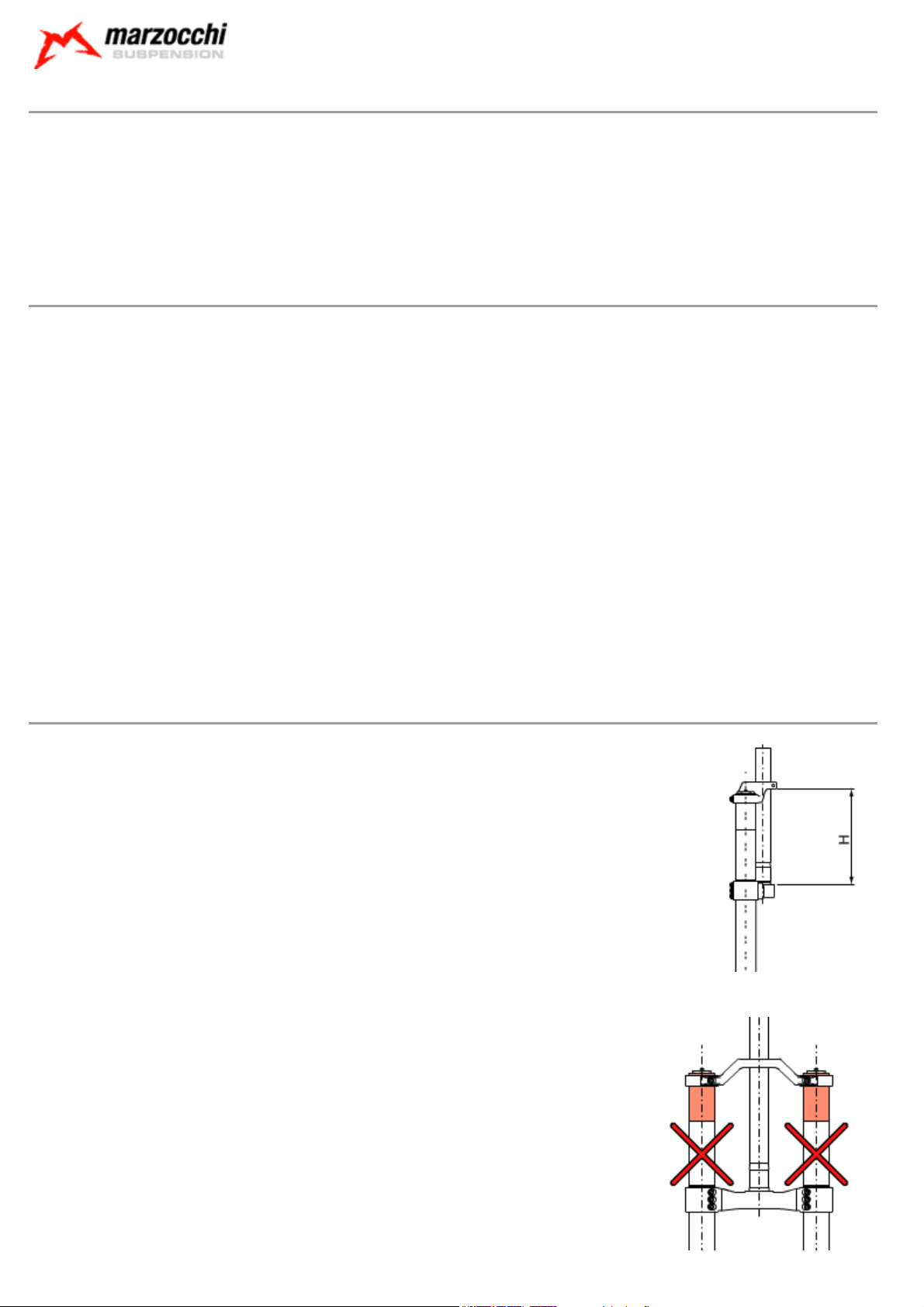
For a correct installation of the fork onto the frame, distance H corresponding to the length of the steer
tube between the steering crowns, must be less than 164 mm (or 184 mm in case of use of a high
steering crown).
Fix the stanchions to the crowns so that the bottom face of the crown is slightly above the reference notch on the stanchion.
The clamping of the stanchions to the crowns must be done only in the areas with larger diameter (darker
area in the picture).
With the fork legs at travel end, the distance between the inflated tire and the bottom of the crown must be at least 4 mm.
Page 10
© Marzocchi Suspension
2005 - 888 VF
A different position of the crowns can result in damage to the fork and in serious personal injury.
Warnings: Installing the disk brake
Installing the brake system is a delicate and critical operation that must be carried out by an authorized Marzocchi Service Center.
Marzocchi is not responsible for the installation and accepts no liability for damage and/or accidents arising from this operation.
Improper installation of a disk brake system can overstress the caliper mountings, which may cause the caliper mountings to break, resulting in loss
of control of the bicycle, an accident, personal injury, or death. Be sure that the brake system installation is also performed in strict compliance with
the instructions provided by the brake system manufacturer.
Improper installation can result in an accident, personal injury, or death.
Use only brake systems that comply with the forks specifications.
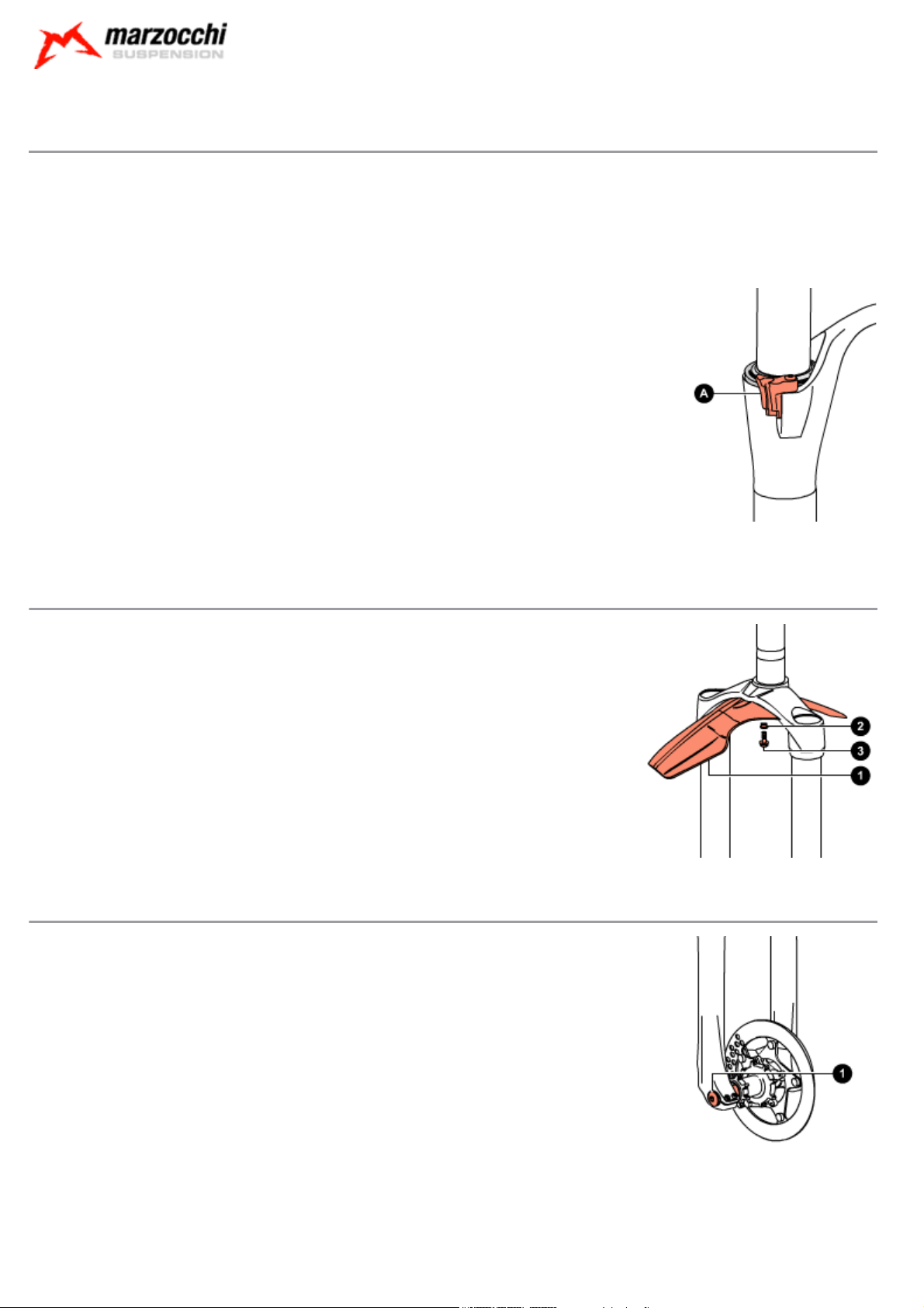
Make sure, after installation, that the brake cable of the brake system is correctly connected
to the proper mounting (A).
The brake cable must never touch the crown and stanchions.
Warnings: Assembling the fender
The fender can be supplied with the fork or purchased separately.
Fender (1) must be assembled by placing the small support bush (2) between the screw and the fender
as shown and by tightening screws (3) with an 8mm fixed spanner to the recommended tightening torque
(6 Nm ±1).
Warnings: Assembling the wheel
For a correct operation of the fork, install the wheel as explained below:
Align the center of the wheel with each wheel axle clamp.
Insert the wheel axle (1) through the right dropout, the wheel and the left dropout.
With the 6mm Allen wrench act on cap (2) and tighten the wheel axle to the recommended tightening
torque (15 Nm ± 1).
Check for the proper fork-wheel alignment. To do this, begin by fully compressing the fork a few times.
The wheel should not make contact with, or come close to any portion of the fork.
Then lift the front of the bicycle and spin the wheel a few times to verify the correct alignment with the
disk brake. The wheel should not wobble from side to side or up and down. Check the owner’s manual of
the brake system for the proper specifications.
Page 11
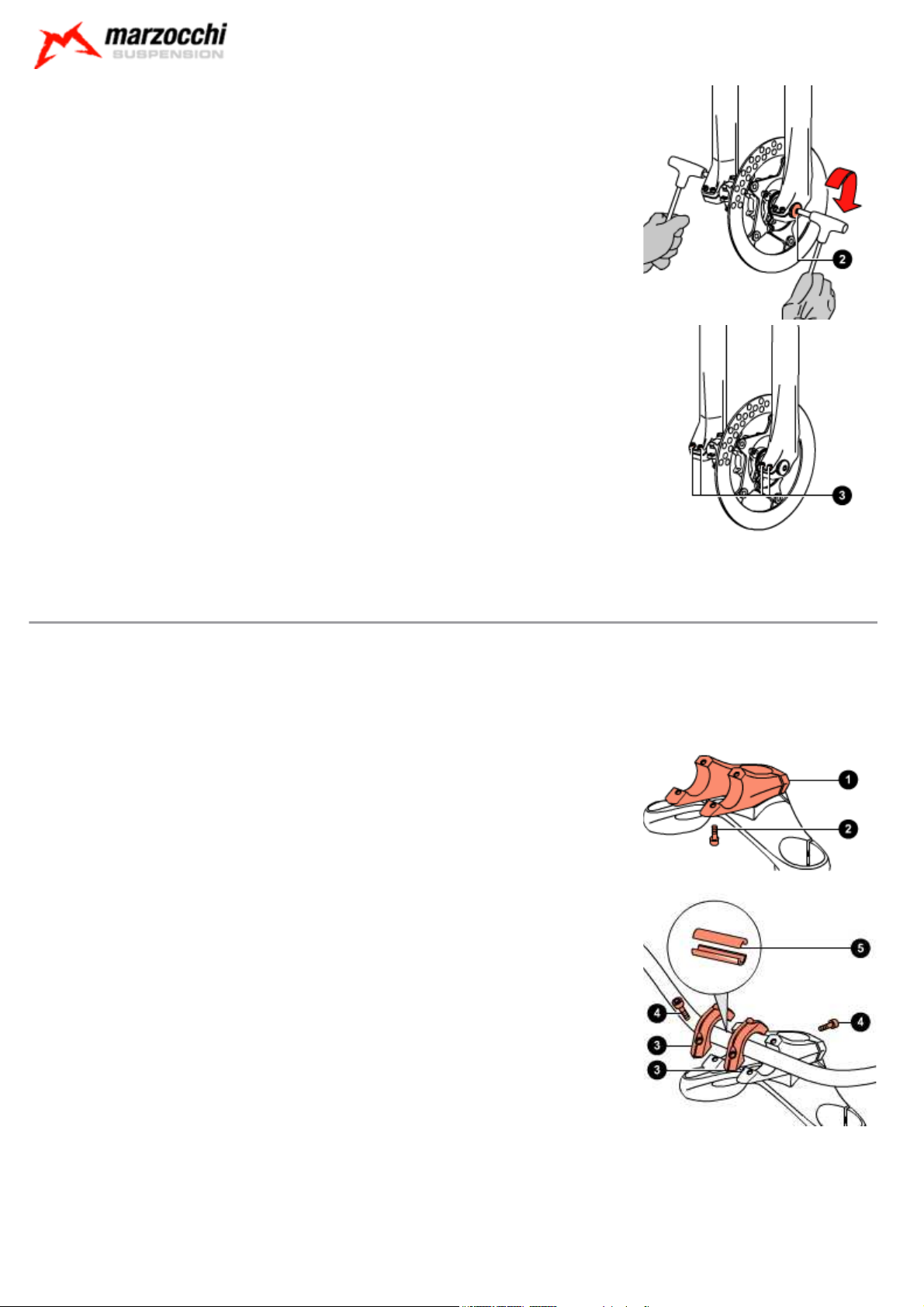
With a 4mm Allen wrench, tighten screws (3) on both dropouts to the recommended tightening torque (6
Nm ±1) following the sequence 1-2-1.
© Marzocchi Suspension
2005 - 888 VF
Warnings: Installing the handlebar mount
For a correct installation of the handlebar mount, follow the instructions below:
Install the bottom handlebar mount (1) onto the top crown so that the fixing holes match.
With a 4mm Allen wrench, lock the handlebar mount tightening screws (2) to the recommended
tightening torque (6 Nm ±1).
Fit the handlebar right in the middle of the mount.
Lock the handlebar in position with the special U-bolts (3).
With a 4mm Allen wrench, tighten screws (4) to the recommended tightening torque (6 Nm ±1).
On request, special adapters (5) are available to install handlebars with a different diameter.
Page 12
© Marzocchi Suspension
2005 - 888 VF
Dismantling: Removing the top caps
Put the fork in the vice in vertical position, fixing it by the dropouts.
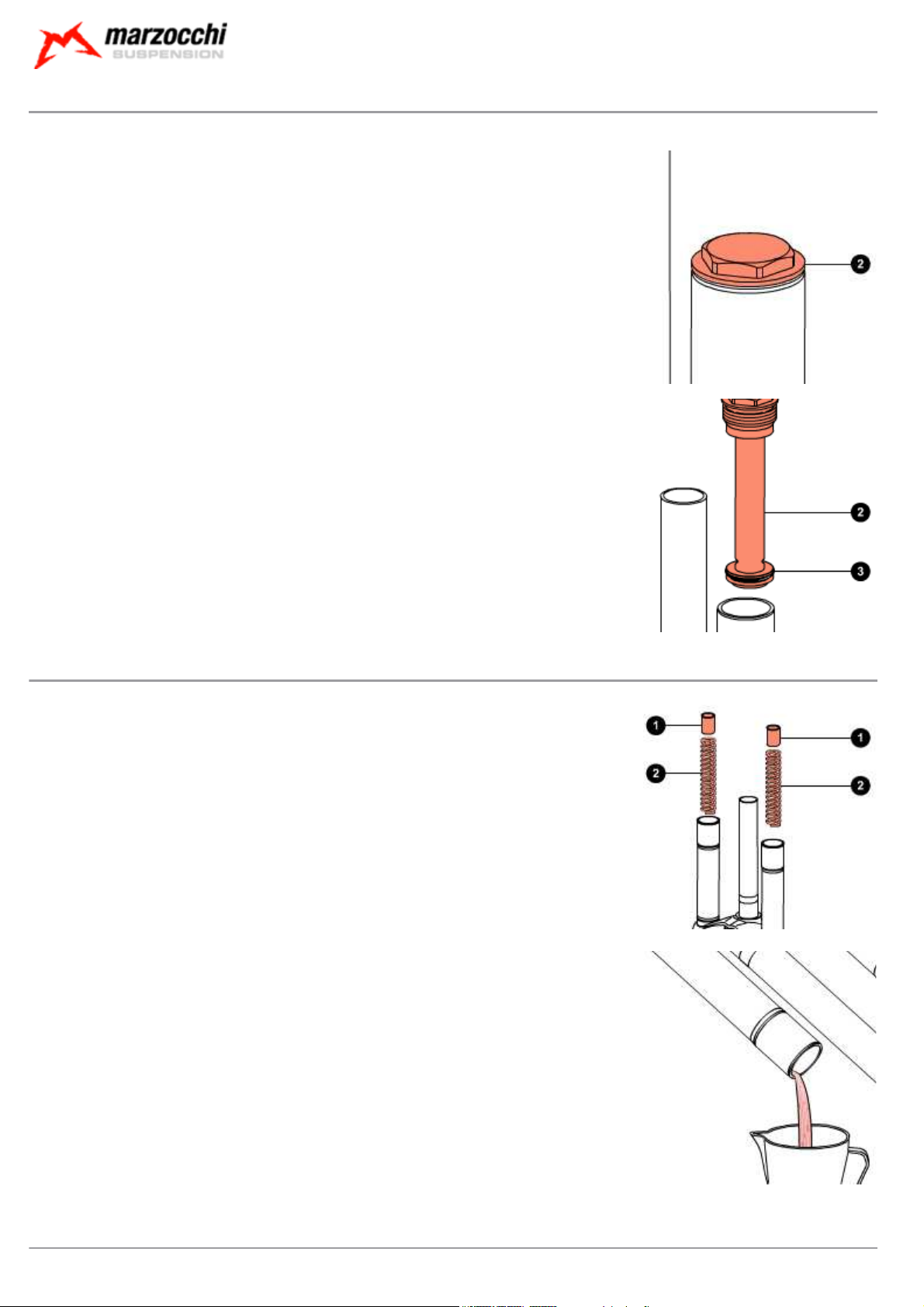
Fully unscrew lock cap (2), with a 28mm fixed spanner.
Remove lock cap (2) being careful not to damage the O-ring (3).
Dismantling: Draining the oil
Remove the preload tube (1) and spring (2) from both legs.
Free the fork from the vice and tip it into a container of a suitable size to drain the oil; compress the fork
a few times to help the oil flow out.
Do not pour used oils on the ground.
Dismantling: Breaking down the steering crown unit / arch-slider assembly
Turn the arch-slider assembly upside down.
Page 13
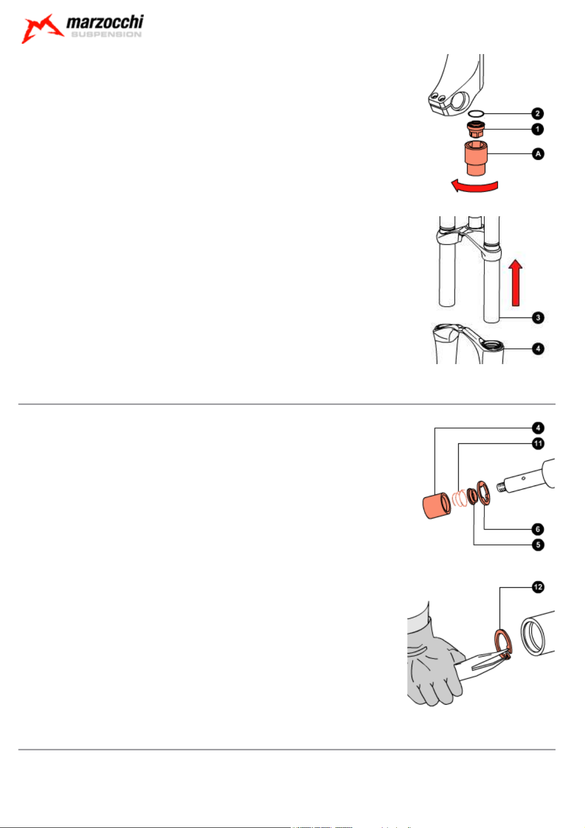
With a 15mm socket spanner, undo the bottom nut (1) on both legs.
Drive bottom nut (1) complete with O-ring (2) off the fork legs.
Pull the crown-stanchion unit (3) off the arch-slider assembly (4).
© Marzocchi Suspension
2005 - 888 VF
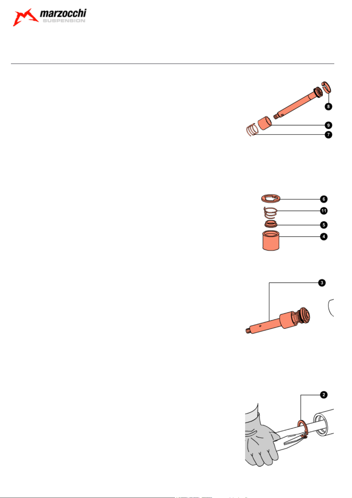
Dismantling: Breaking down the pumping element
Remove bushing (4), valve (5), the conical spring (11) and the three-point ring (6) from the piston rod.
Using the special round-nose pliers, remove the internal stop ring (12).
Dismantling: Dismantling the pumping element and valve
Remove the bottom pad (1).
Page 14
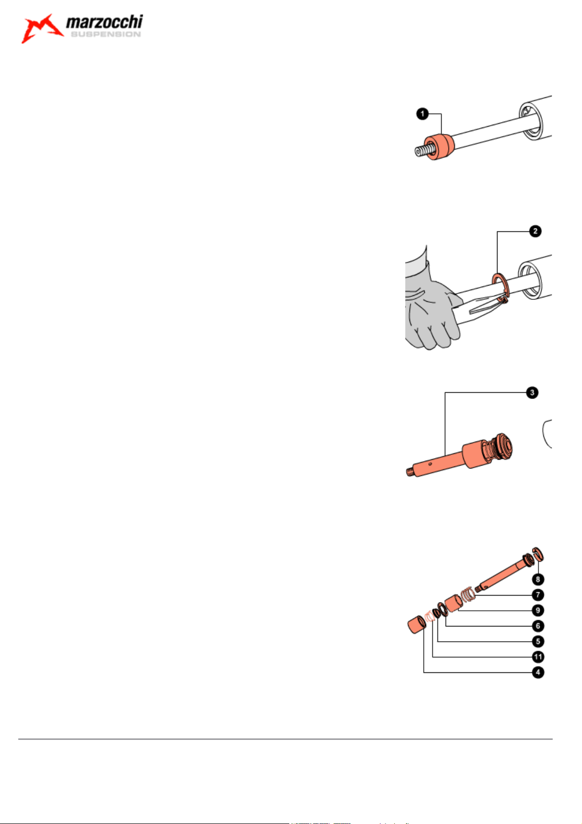
Using the special round-nose pliers, remove stop ring (2).
© Marzocchi Suspension
2005 - 888 VF
Pull out the pumping element (3) complete with rebound spring and valve.
Remove bushing (4), conical spring (11), valve (5) and three-point ring (6) from the pumping element.
Remove the preload tube (9) (
Remove the rebound spring (7).
only for models with 170mm travel
).
If the piston segment (8) is damaged, you can prize it off with a small flat-tip screwdriver.
Dismantling: Removing the seals
Prize the dust seal (1) off its seat with a small flat-tip screwdriver.
Take great care not to damage the internal surfaces of the one-piece assembly while
removing the dust seal.
Page 15
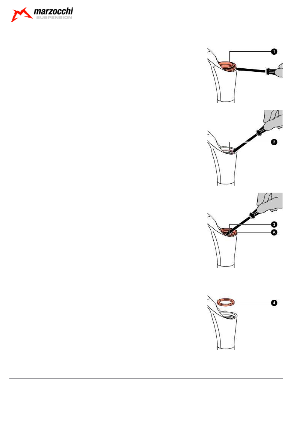
With the same screwdriver, prize off the metal stop ring (2).
Take great care not to damage the internal surfaces of the one-piece assembly while
removing the stop ring.
© Marzocchi Suspension
2005 - 888 VF
Protect the upper part of the slider with the special tool (A).
With a screwdriver, prize off the sealing ring (3).
Remove the sealing ring (3).
Take great care not to damage the internal surfaces of the one-piece assembly while
removing the sealing ring.
Remove the spring cup (4).
The old sealing rings and dust seals must not be used again.
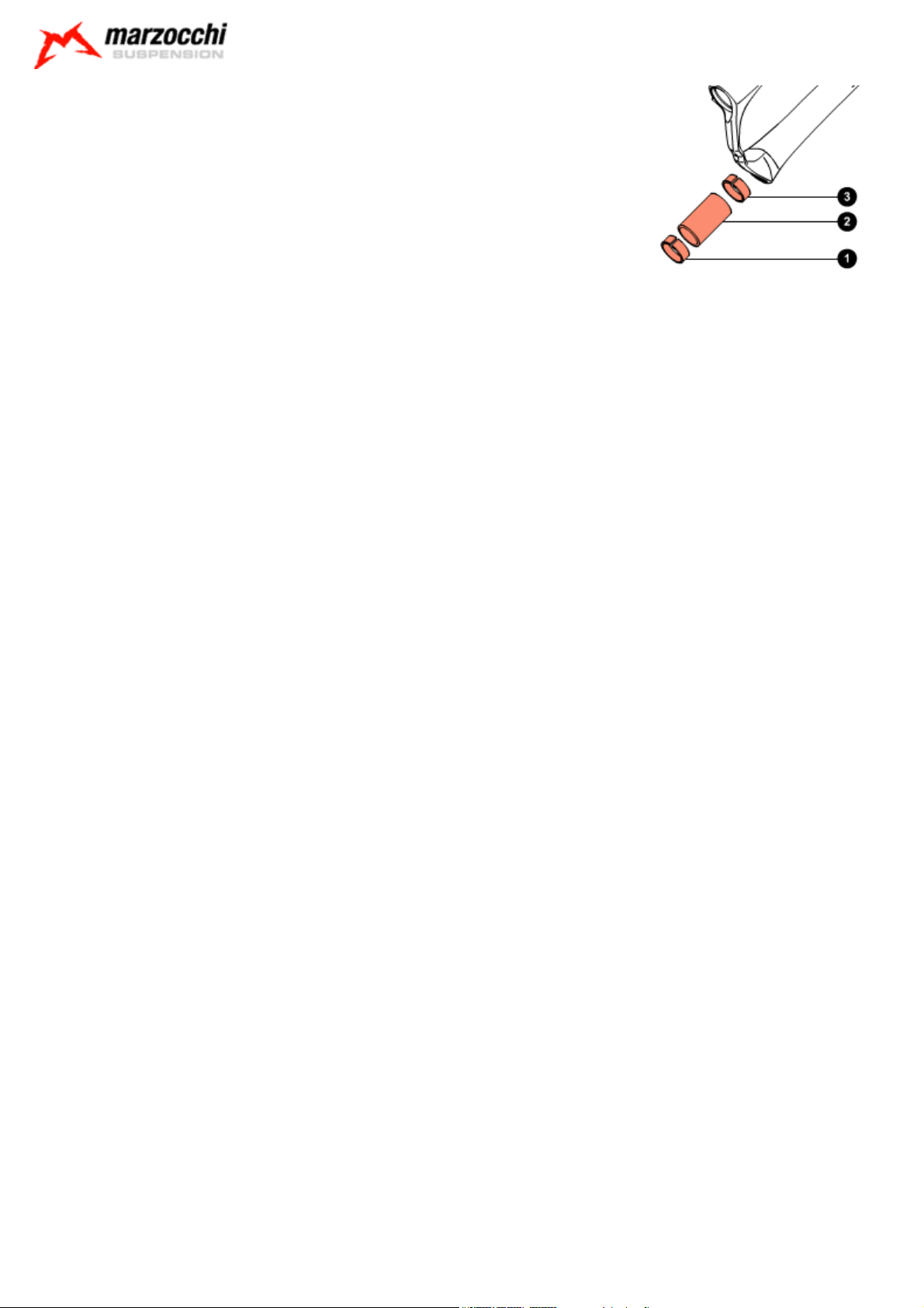
Dismantling: Removing the guide bushes
Knock the top end of the one-piece assembly against a wooden surface and remove the top guide bush
(1), spacer (2) and the bottom guide bush (3).
Do this operation with extreme caution and hold the one-piece assembly perpendicular to the
wooden surface.
Page 16
© Marzocchi Suspension
2005 - 888 VF
Page 17
© Marzocchi Suspension
2005 - 888 VF
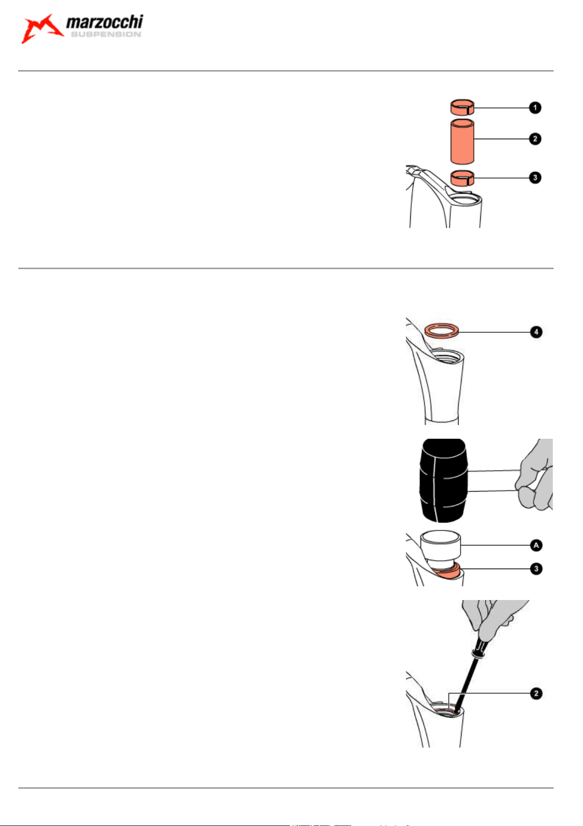
Assembling: Assembling the guide bushes
Fit the bottom guide bush (3).
With the help of spacer (2), press the bottom guide bush into the arch-slider assembly.
Insert the top guide bush (1) in its seat.
To help the bushes enter their seats you can use the special introducer.
Assembling: Assembling the seals
Insert the spring cup (4) in its seat.
Smear the dust seal and the sealing ring with some grease.
Insert the sealing ring (3) in its seat with the special introducer (A).
Using a hammer, knock in introducer (A) and drive the sealing ring home into the arch-slider assembly.
Using a small flat-tip screwdriver, fit the stop ring (2) and check that it fits perfectly into its groove.
Take great care not to damage the internal surfaces of the one-piece assembly when fitting
the stop ring.
The dust seals shall be refitted when reassembling the crown-stanchion unit / arch-slider assembly.
Assembling:
During the assembly of the pumping unit, strictly obey the instructions below.
Page 18
© Marzocchi Suspension
2005 - 888 VF
Do not, at any times, reverse the position of the pumping elements in the fork legs (if you are unsure about anything, please refer
to the relevant exploded view).
Assembling: Assembling the left pumping element and valve
Replace the segment (8) of the pumping element, if necessary.
Insert the rebound spring (7) and the preload tube (9) (
rod.
Assemble the valve unit in this order: bushing (4),valve (5), conical spring (11), three-point ring (6), and
check that the parts are oriented as shown.
only for models with 170mm travel
) in the piston
Insert the pre-assembled valve in the piston rod from the three-point ring side as shown.
Insert the valve and the pumping element (3) into the stanchion.
Take great care not to damage the segment and if necessary use a small flat-tip screwdriver to help the piston of the pumping
element into the stanchion.
Using the special round-nose pliers, mount the stop ring (2) and check it fits perfectly into its groove.
Fit the bottom pad (1) to the pumping element rod.
Page 19
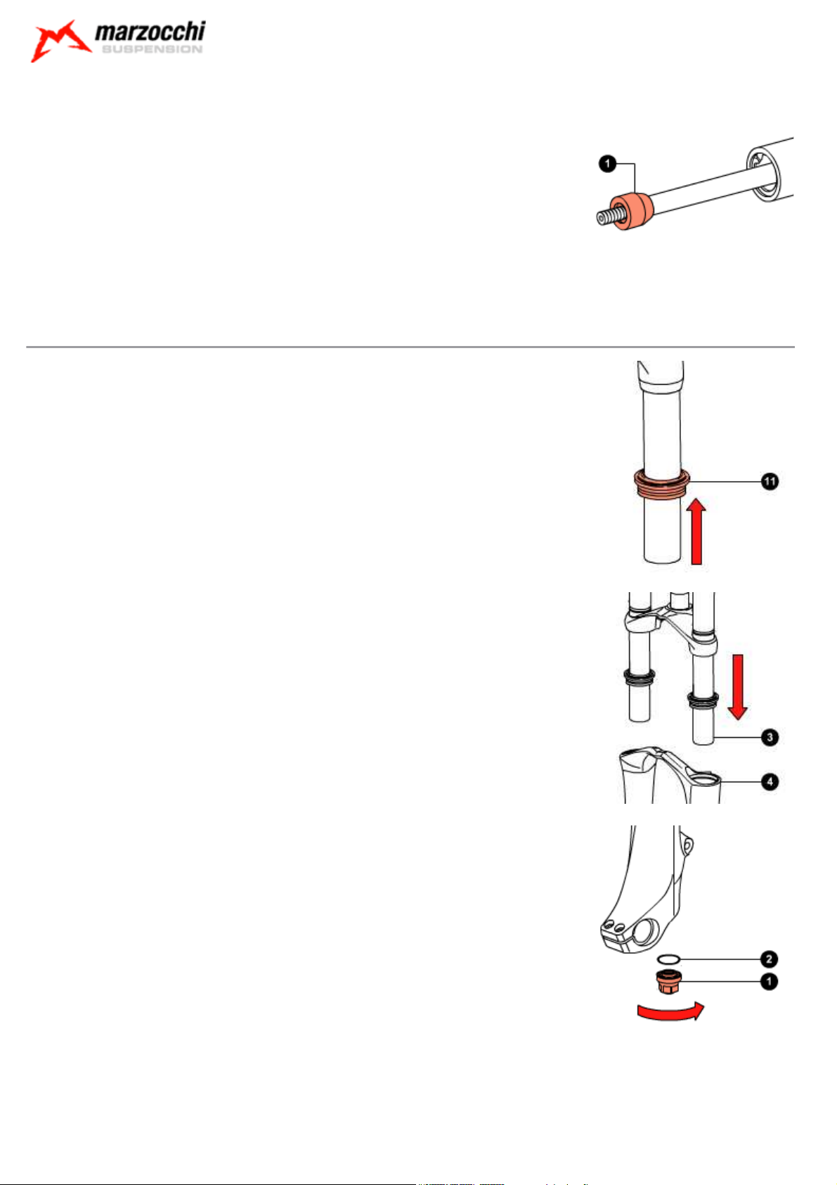
Assembling: Reassembling the steering crown unit / arch-slider assembly
A special spanner shall be used to assemble the bottom nuts. Do not, at any times, use other
tools.
Fit both dust seals (11) to the stanchions.
© Marzocchi Suspension
2005 - 888 VF
Insert the crown-stanchion unit (3) in the arch-slider assembly (4).
With the 15mm socket spanner, tighten the bottom nut (1) complete with O-ring (2) of both legs to the
recommended tightening torque (10 Nm ± 1).
Using introducer (A) insert the dust seals (11) in their seats.
Page 20
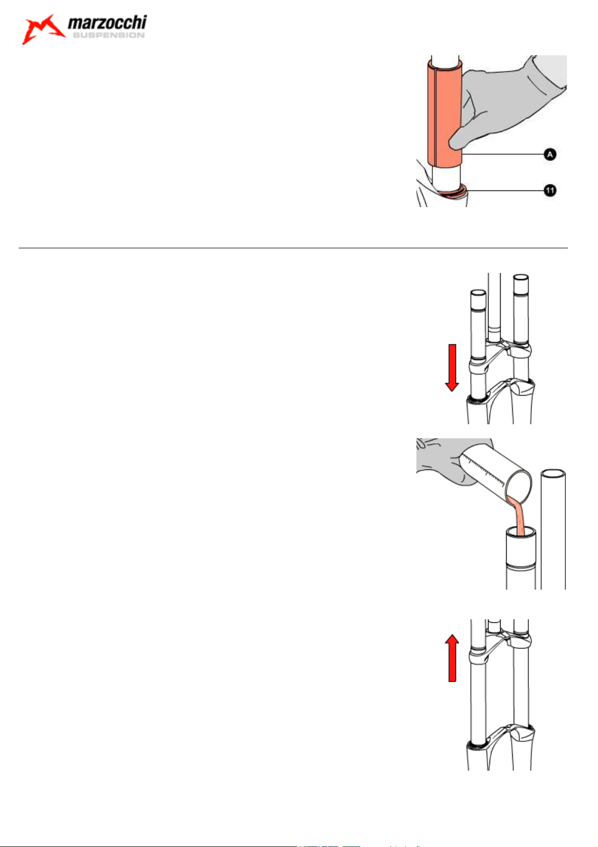
Assembling: Filling with oil
Block the fork in the vice, in perfectly vertical position.
Lower the crown-stanchion unit on the arch-slider assembly.
© Marzocchi Suspension
2005 - 888 VF
In a graduated recipient, prepare the quantity of oil to pour into the fork leg (see table).
Pour roughly 1/3 of the oil required into each stanchion, then pump the fork a few times to eliminate any
traces of air.
Pour the rest of oil in.
A lower or higher volume or a type of oil other than the one recommended can change the behaviour of the fork in every phase.
Lift the crown-stanchion unit on the arch-slider assembly.
Insert spring (2) and the preload tube (1) in both legs.
Page 21
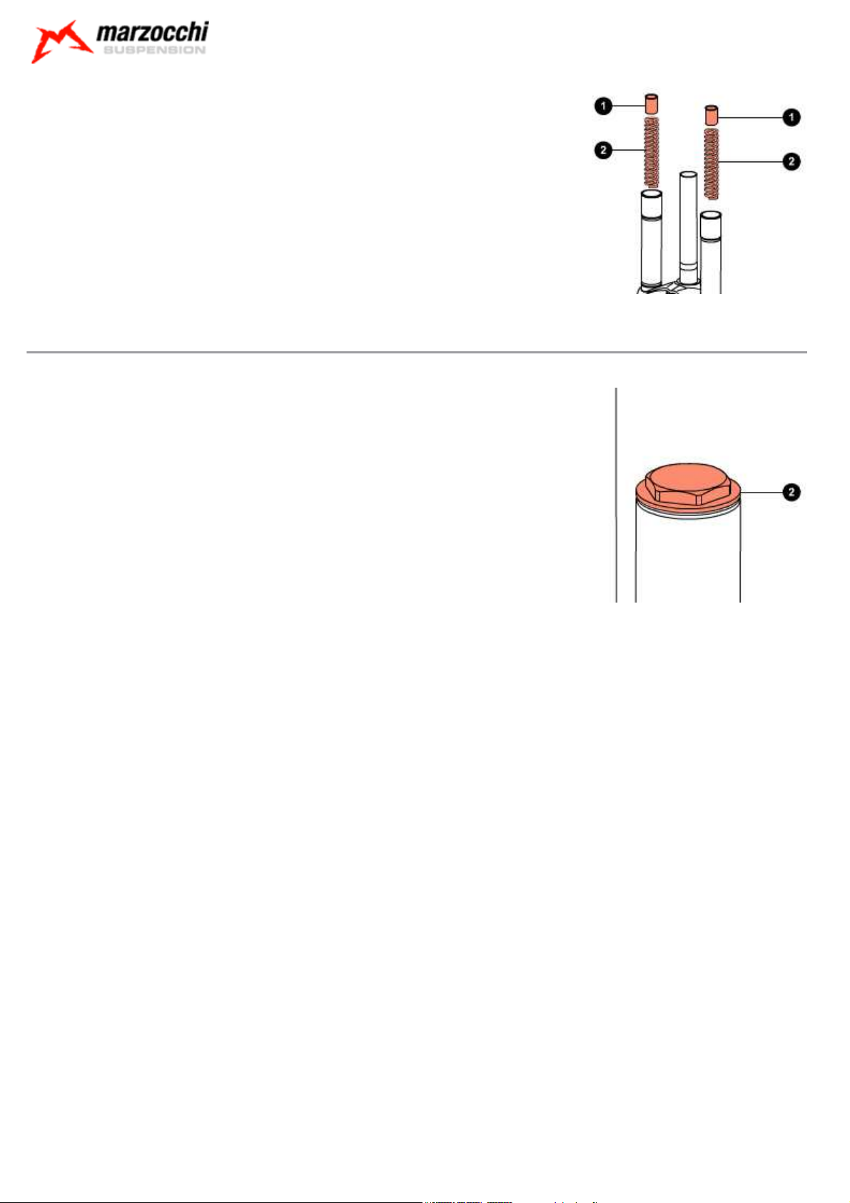
Assembling: Mounting the top caps
Put the fork in the vice in vertical position, fixing it by the dropouts.
Using the 28mm fixed spanner, tighten cap (1) to the recommended tightening torque (10 Nm ± 1).
© Marzocchi Suspension
2005 - 888 VF
Page 22
© Marzocchi Suspension
2005 - 888 VF
Setting: General rules for calibration
By carefully calibrating the damping system you can get the maximum performance out of the same.
This paragraph indicates the sequence of operations to perform to set up the Marzocchi forks correctly.
In order to find the best settings for you, you will need to try several times to understand where and how to make adjustments. When doing so,
please ride in an open area, free from traffic, obstacles and other hazards.
The optimal setting is influenced by the geometry of the frame of the mountain bike, the weight of the cyclist, the type of terrain the bike will be
used on and the type of obstacles you have to deal with, but also by subjective factors associated with your riding style; therefore it is impossible to
provide objective data on the desired settings.
Nevertheless by carefully following the instructions below you will soon be able to find the optimal setting for you.
The shock absorber must be calibrated simply by using one adjuster at a time, following the order explained, noting the operations and any result
step-by-step.
During setting don't force the adjusters beyond their limit of travel and don't exceed the max recommended air pressure.
To keep the pressure inside the fork’s legs, only use the special MARZOCCHI pump with pressure gauge.
The use of any other pump can compromise the inflating operation and cause malfunction or damage to the fork, resulting in an
accident, personal injury or death.
Once the correct setting has been found, we recommend noting the number of clicks or turns of the adjuster with respect to the "fully closed"
position (adjuster fully clockwise) for a faster re-setting of your fork in case of need.
Setting: SAG
SAG means the fork bottoming under the biker's weight.
How to measure the SAG:
Follow these simple steps to measure the SAG.
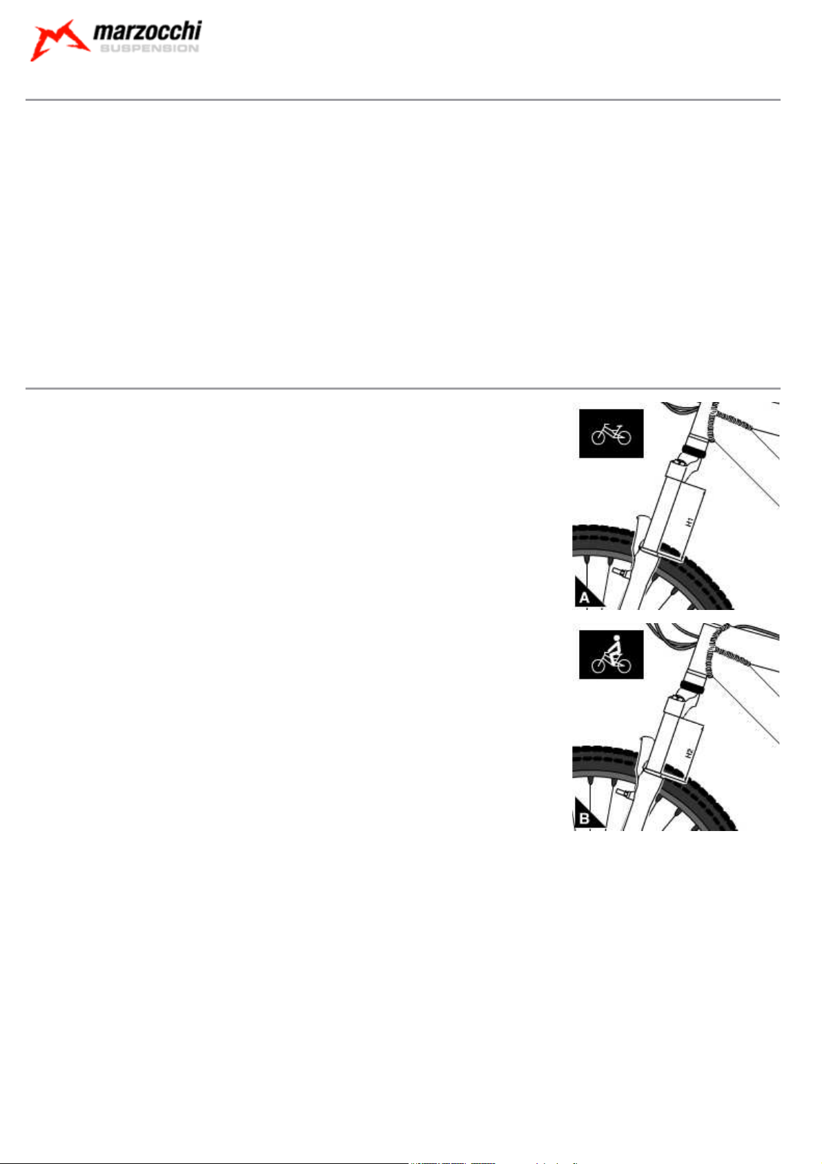
On the leg portion of the fork, measure the distance between the lower crown and the dust seal (see
Picture A). Note this value as “H1”.
While sitting on the bike, repeat the measurement (see picture B). Note this value as “H2".
SAG = H1 - H2
How to find the best percent SAG:
The best percent SAG is 15-20% for Cross-country and All Mountain forks and 25-30% for Freeride and
Downhill forks.
In order to calculate the best SAG for your own fork, you will need to make the following calculation:
SAG = T x S (T = total travel; S = suggested sinking percentage).
Page 23

© Marzocchi Suspension
2005 - 888 VF
Tightening torques
Components Tightening torque (Nm)
Bottom crown fixing screws 6±1
Fender fixing screws 6±1
Fork leg top caps 10±1
Handlebar fixing screws 6±1
Pumping element/cartridge bottom nuts 10±1
Top crown fixing screws 6±1
Wheel axle Allen screws 6±1
Wheel axle screws 15±1
Air pressures
Preload air pressure
User weight Air pressure
kg. lb. bar psi
0 - 110+ 0 - 242 0 - 1,00 0,00 - 1.450,00
888 VF 170 - Oil levels
Position Oil type Quantity (cc)
Right fork leg SAE 7,5 - 550013 220
Left fork leg SAE 7,5 - 5500 13 220
888 VF 200 - Oil levels
Position Oil type Quantity (cc)
Right fork leg SAE 7,5 - 550013 220
Left fork leg SAE 7,5 - 5500 13 220
Page 24

© Marzocchi Suspension
2005 - 888 VF
Diagnostics
Finding the problem Finding the possible cause Possible solutions proposed
Fork doesn't get full travel Oil level too high Check oil levels
Fork doesn't get full travel Spring rate too stiff Change to softer spring rate
Fork doesn't get full travel Spring rate too stiff Decrease air pressure
Fork extends too quickly; harsh top-out after
impacts
Fork has too much sag Oil is too fluid Check oil levels
Fork has too much sag Spring rate too soft Change to stiffer spring rate
Fork has too much sag Spring rate too soft Increase air pressure
Fork has too much sag Spring rate too soft
Fork is “sticky”; fork does not perform as new
Fork is too soft, but the sag is the one
recommended
Fork is too soft, needs more than the maximum
preload
Fork is too soft, needs more than the maximum
preload
Fork is too soft, needs more than the maximum
preload
Front wheel tends to tuck under while turning left
or right
Heavy amount of oil on stanchions; oil dripping
down legs
Heavy amount of oil on stanchions; oil dripping
down legs
Loss of sensitivity Old oil Change the oil
Loss of sensitivity Sliding bushes worn Renew the sliding bushes
Oil leaking from the bottom of the fork leg Bottom nut/screw loose Tighten the nut or screw
Oil ring on stanchions Sealing rings dirty Renew all seals
Rebound damping is not enough
Dirty sealing rings; fork needs to be
serviced
Compression damping is not enough
Oil is too fluid Check oil levels
Spring rate too soft Change to stiffer spring rate
Spring rate too soft Increase air pressure
Spring rate too soft Change to stiffer spring rate
Sealing rings damaged Renew all seals
The stanchion tubes could be damaged Have the stanchions be checked
Replace the oil (SAE 7.5) with one of higher
viscosity index
Increase spring preload by replacing the preload
tube
Renew all seals
Increase compression damping by changing oil
volumes
 Loading...