

Page 1

24” Marvel High Efciency
Single Zone Wine Cellar
Model # ML24WS****
• Dynamic Cooling Technology™ delivers rapid cooldown and the
industry’s best temperature stability
• MARVEL Intuit™ Integrated Controls provide precise temperature
management from 40°F to 65°F
• Vibration Neutralization System™ protects wine from vibration
• Thermal-efcient cabinet ensures optimum wine preser vation and
energy efciency while maximizing capacity
• Tinted, UV-resistant dual pane glass door protects wine from
damaging ultra-violet light
• Two-stage, soft white theatre-style LED lighting and midnight black
interior
• Natural maple shelf fronts are stainable to match cabinetry
• Three-quarter extension roller-glide shelf system prevents jarring
• Close Door Assist System™ gently and automatically closes door
• Panel overlay option features soft-close integrated hinge for a truly
ush t with cabinetry
• Audible and visual alarms signal when door is left ajar to protect wine
integrity and energy use
• Vacation/Sabbath mode conserves energy during times when the
unit is not in use and complies with Star-K requirements
• Sleek stainless steel door, designer handle and adjustable black toe
grill
• Height adjustment up to 1” with leveling legs
• Up to 2x more efcient than leading competitors
• 4” black adjustable toe kick
• 1-year warranty
Ordering
Details
Stainless Frame Glass Door, Right
Hinge
Stainless Frame Glass Door, Left
Hinge
Smooth Black Frame Glass Door,
Right Hinge
Smooth Black Frame Glass Door, Left
Hinge
Panel Overlay Frame Glass Door,
Integrated Right Hinge
Panel Overlay Frame Glass Door,
Integrated Left Hinge
Solid Panel Overlay Ready Door,
Integrated Right Hinge
Solid Panel Overlay Ready Door,
Integrated Left Hinge
No panel installation kit required.
ML24WSG2RS
ML24WSG2LS
ML24WSG2RB
ML24WSG2LB
ML24WSF3RP
ML24WSF3LP
ML24WSP3RP
ML24WSP3LP
Storage Capacity
Up to 45 bottles total
Storage Conguration
(1) 5-bottle gallery display wine rack
(5) 8-bottle roller-glide wine racks
Product Dimensions
1
/
23⅞” W x 33¾” minimum H x 24
16
” D
(including handle)
Finish/Door Options
BlackStainless Steel
Wood Overlay
(Panel Ready)
Page 2
Side
Front
Side
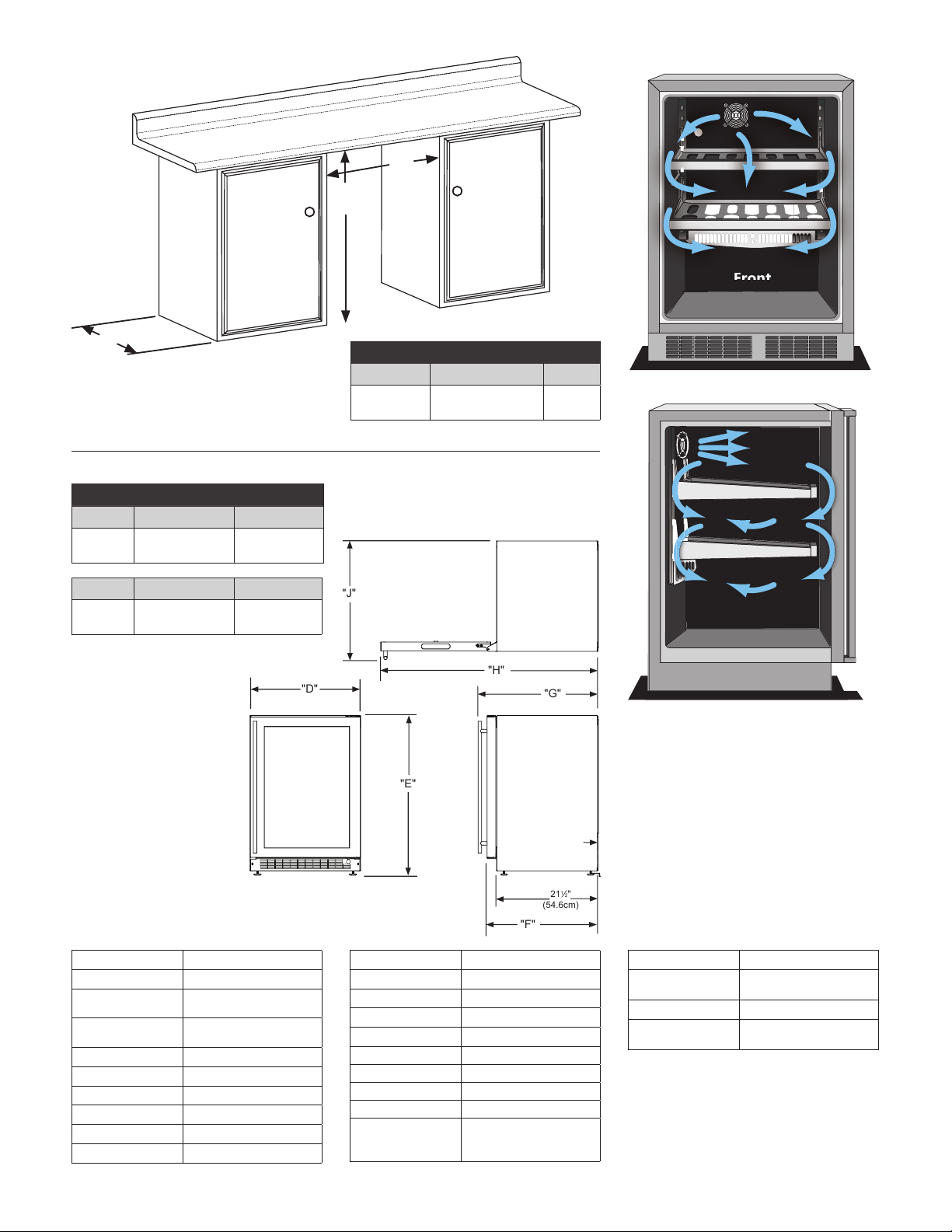
Forced
Air Fan
Evaporator
Plate
Return
Air Intake
"F"
"D"
"E"
"H"
"J"
"G"
PRODUCT DIMENSIONS
PRODUCT
WEIGHT
105 lbs
(47.7 kg)
105 lbs
(47.7 kg)
140 lbs
(63.6 kg)
140 lbs
(63.6 kg)
Figure 8
211⁄2"
(54.6cm)
1"
(2.5 cm)
"B"
"A"
"C"
Cabinet Dimensions
"D" "E" "F"
23 7⁄8”
(60.7 cm)
“G” “H” “J”
25 21⁄32”
(65.2 cm)
33 3⁄4” to 34 3⁄4”
(85.7 to 88.3 cm)
46 13⁄32”
(117.9 cm)
23 23⁄ 32”
(60. 2 cm)
25 11⁄16”
(65.2 cm)
24" Rough-In Dimensions
"A" "B" "C"
24”
(61 cm)
**34" to 35"
(86.4 to 88.9 cm)
24”
(61 cm)
Dynamic Cooling Technology™
delivers rapid cool down
and the industry’s best
temperature stability
The distinctive Marvel design features a
thermal-efcient cabinet and door combined
with Dynamic Cooling Technology™ for
superior temperature stability, faster cooling
times and speedy temperature recovery even
with high frequency.
Width 23 ⅞"
Interior Finish Black
Capacity Up to 45 wine bottles
Shelving System Side mount - tray
Shelf Fronts Black painted maple
Other Storage 1 roll-o ut 5 bottle disp lay rack
Interior Lighting 2 White LED Pods
Toe Grill Finish Black
Hinge Classic Hinge
Handle Designer
Contr ol Type Intui t™
Temperature Range 40° - 65° F
Lock NA
Electrical Requirements 120V / 60Hz / 15A
Length of Power Cord 5'
Product Dimensions 23 ⅞" W x 33 ¾" H x 21 ½" D
Depth to Front of Door 23
Depth to Handle 25
Depth with door at 90° 46
Shipping Weight 160 lbs
Finishes SS, B, O
Vacation /
Sabba th Mode
Agency Approvals CSA
Energ y Star Certied NA
23
/32"
21
/32"
13
/32"
Finishes Key
SS = Stainless Steel
Yes
B = Black
O = Overlay
Page 3
Overlay Panels
!
CAUTION
Material Type #10 Wood Screw
Hardwood
1
⁄8" (3.2 mm) Diameter. Pilot Hole
Softwood
7
⁄64 (2.8 mm) Diameter. Pilot Hole
Table C
Weight of overlay door panel must not exceed 15
pounds (6.8 kg) for a solid door model or 10 pounds
(4.5 kg) for a glass door model.
Press and hold down this
tab on the wire connector
and pull the connector apart.
OVERLAY DOOR PANEL INSTALLATION
Figure 13
Left Hand Hinged Door
15" (38.1 cm) wide appliance
Figure 11
Overlay panel to
be centered on
width of door.
Overlay panel
ush with top
and side of
door.
Holes in
gasket
retainer.
Figure 12a
Clearance for
screw head,
4 places
Clearance
for hinge
2 places
Hinge side of door
143⁄4"
(37.5 cm)
1
⁄4" (6 mm)
Deep
47⁄8"
(12.4 cm)
5"
(12.7 cm)
1" (25.4 mm) diameter
counter bore
1
⁄4" (6.4mm)
deep 4 places.
13⁄16"
(3 cm)
3
1
⁄8"
(7.9 cm)
13⁄4"
(4.4 cm)
27
!
CAUTION
Hardwood
1
⁄8" (3.2 mm) Diameter. Pilot Hole
Softwood
7
⁄64 (2.8 mm) Diameter. Pilot Hole
Table C
Figure 21
#10 x 1/2"
screw
!
CAUTION
Weight of overlay door panel must not exceed 15
pounds (6.8 kg) for a solid door model or 10 pounds
(4.5 kg) for a glass door model.
Material Type #10 Wood Screw
Hardwood
1
⁄8" (3.2 mm) Diameter. Pilot Hole
Softwood
7
⁄64 (2.8 mm) Diameter. Pilot Hole
Table C
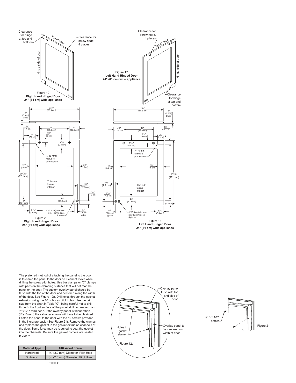
Step 4: Assemble the panel to the door
The preferred method of attaching the panel to the door
is to clamp the panel to the door so it cannot move while
drilling the screw pilot holes. Use bar clamps or "C" clamps
with pads on the clamping surfaces that will not mar the
panel or the door. The custom overlay panel should be
ush with the top of the door and centered along the width
of the door. See Figure 12a. Drill holes through the gasket
extrusion using the 10 holes as pilot holes. Use the drill
size from the chart in Table "C", being careful not to drill
through the front surface of the panel, drill no deeper than
1
⁄2" (12.7 mm) deep. If the overlay panel is thinner than
5
⁄8" (16 mm) thick shorter screws will have to be obtained.
Fasten the panel to the door with the 10 screws provided
in the literature pack. (See Figure 21). Remove the clamps
and replace the gasket in the gasket extrusion channels of
the door. Some force may be required to seat the gasket
into the channels. Be sure the gasket corners are seated
properly.
1
5
⁄32"
(2.9 cm)
Clearance for
screw head,
4 places
Hinge side of door
Clearance
for hinge
at top and
bottom
Figure 17
Left Hand Hinged Door
24" (61 cm) wide appliance
Figure 18
Left Hand Hinged Door
24" (61 cm) wide appliance
Top of door
233⁄4"
(60.3 cm)
1
3
⁄4"
(4.4 cm)
1
⁄4"
(6 mm)
Deep
1" (2.5 cm) diameter
x
1
⁄4" (6 mm) deep
4 places
3
1
⁄8"
(7.9 cm)
2"
(5.1 cm)
3
11
⁄16"
(9.4 cm)
1
1
⁄2"
(3.8 cm)
typical
1
11
⁄16"
(4.3 cm)
3011⁄32"
(77.1 cm)
31⁄8"
(7.9 cm)
1
⁄4" (6 mm)
radius is
permissible
327⁄32"
(9.8 cm)
4
7
⁄8"
(12.4 cm)
14"
(35.6 cm)
1
3
⁄16"
(3 cm)
3
1
⁄8"
(7.9 cm)
41⁄8"
(10.5 cm)
This side
facing
interior
!
CAUTION
Weight of overlay door panel must not exceed 15
pounds (6.8 kg) for a solid door model or 10 pounds
(4.5 kg) for a glass door model.
OVERLAY DOOR PANEL INSTALLATION
Clearance
for hinge
at top and
bottom
Top of door
Clearance for
screw head,
4 places
Figure 19
Right Hand Hinged Door
24" (61 cm) wide appliance
Hinge side of door
233⁄4"
(60.3 cm)
Figure 20
Right Hand Hinged Door
24" (61 cm) wide appliance
31⁄8"
(7.9 cm)
31⁄8"
(7.9 cm)
13⁄4"
(4.4 cm)
2"
(5.1 cm)
3
11
⁄16"
(9.4 cm)
1
⁄4"
(6 mm)
Deep
3011⁄32"
(77.1 cm)
1" (2.5 cm) diameter
x 1⁄4" (6 mm) deep
4 places
3
1
⁄8"
(7.9 cm)
11⁄2"
(3.8 cm)
typical
1
11
⁄16"
(4.3 cm)
4
7
⁄8"
(12.4 cm)
14"
(35.6 cm)
1
3
⁄16"
(3 cm)
3
27
⁄32"
(9.8 cm)
1
⁄4" (6 mm)
radius is
permissible
This side
facing
interior
41⁄8"
(10.5 cm)
Material Type #10 Wood Screw
Hardwood
1
⁄8" (3.2 mm) Diameter. Pilot Hole
Softwood
7
⁄64 (2.8 mm) Diameter. Pilot Hole
Table C
Figure 21
#10 x 1/2"
screw
Step 4: Assemble the panel to the door
The preferred method of attaching the panel to the door
is to clamp the panel to the door so it cannot move while
drilling the screw pilot holes. Use bar clamps or "C" clamps
with pads on the clamping surfaces that will not mar the
panel or the door. The custom overlay panel should be
ush with the top of the door and centered along the width
of the door. See Figure 12a. Drill holes through the gasket
extrusion using the 10 holes as pilot holes. Use the drill
size from the chart in Table "C", being careful not to drill
through the front surface of the panel, drill no deeper than
1
⁄2" (12.7 mm) deep. If the overlay panel is thinner than
5
⁄8" (16 mm) thick shorter screws will have to be obtained.
Fasten the panel to the door with the 10 screws provided
in the literature pack. (See Figure 21). Remove the clamps
and replace the gasket in the gasket extrusion channels of
the door. Some force may be required to seat the gasket
into the channels. Be sure the gasket corners are seated
properly.
15⁄32"
(2.9 cm)
For comprehensive installation instructions,
please visit www.marvelrefrigeration.com
 Loading...