

Page 1
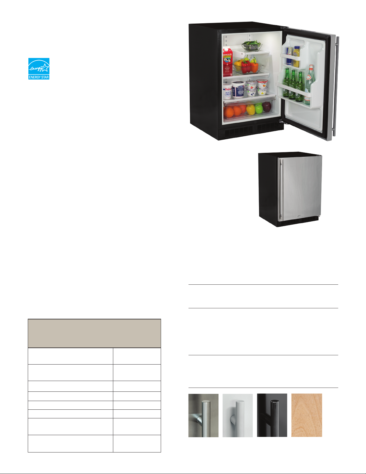
24” Marvel All Refrigerator
with MaxStore
Model # ML24RA****
Certied to meet
ENERGY STAR® requirements
• Dynamic Cooling Technology™ delivers rapid cooldown and the
industry’s best temperature stability
• MARVEL Intuit™ Integrated Controls ensures precise temperature
management from 34°F to 42°F
• MaxStore™ roller-glide clear utility bin provides maximum volume to
effectively store large, bulky or loose items
• Tall item storage: Half-width interior shelf and extra door storage
allows for high-clearance vertical storage
• Pristine arctic white interior easily wipes clean and efcient white LED
lighting illuminates interior for better viewing
• Close Door Assist System™ gently and automatically closes door
• Panel overlay option features soft-close integrated hinge for a truly
ush t with cabinetry
• Audible and visual alarms signal when door is lef t ajar to protect food
integrity and energy use
• Vacation/Sabbath mode conserves energy during times when the
unit is not in use and complies with Star-K requirements
• Height adjustment up to 1” with leveling legs
• 4” black adjustable toe kick
• 1-year warranty
™
Utility Bin
Ordering
Details
Solid Stainless Steel Door, Right
Hinge
Solid Stainless Steel Door, Left
Hinge
Smooth White Door, Right Hinge ML24RAS2RW
Smooth White Door, Left Hinge ML24RAS2LW
Smooth Black Door, Right Hinge ML24RAS2RB
Smooth Black Door, Left Hinge ML24RAS2LB
Solid Panel Overlay Door,
Integrated Right Hinge
Solid Panel Overlay Door,
Integrated Left Hinge
No panel installation kit required.
ML24RAS2RS
ML24RAS2LS
ML24R AP3RP
ML24R AP3LP
Storage Capacity
Up to (115) 12-oz cans
Storage Conguration
(1) full-width and (1) half-width cantilevered, fully adjustable
white steel-framed glass shelves
(1) xed steel-framed glass shelf
(1) MaxStore
™
Utility Bin
Product Dimensions
23⅞” W x 33¾” minimum H x 25⅝” D
(including handle)
Finish/Door Options
Stainless Steel
White
Black
Wood Overlay
(Panel Ready)
Page 2
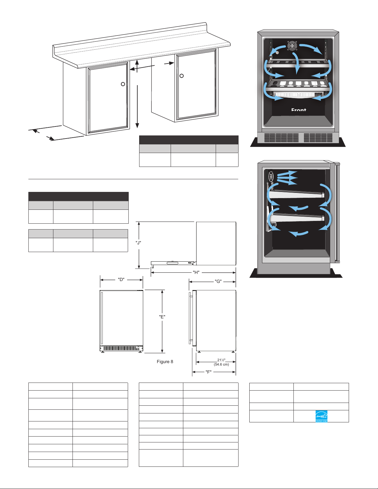
Side
Front
Side
Forced
Air Fan
Evaporator
Plate
Return
Air Intake
"F"
211⁄2"
(54.6 cm)
PRODUCT
WEIGHT
105 lbs
(47.7 kg)
105 lbs
(47.7 kg)
140 lbs
(63.6 kg)
140 lbs
(63.6 kg)
140 lbs
(63.6 kg)
140 lbs
((63.6 kg)
"D"
"E"
"H"
"J"
"G"
PRODUCT DIMENSIONS
Figure 8
"B"
"A"
"C"
Cabinet Dimensions
"D" "E" " F"
23 7⁄8”
(60.7 cm)
“G” “H” “J”
25 21⁄32”
(65.2 cm)
33 3⁄4” to 34 3⁄4”
(85.7 to 88.3 cm)
46 13⁄32”
(117.9 cm)
23 23⁄ 32”
(60.2 cm)
25 11⁄16”
(65.2 cm)
24" Rough-In Dimensions
"A" "B" "C"
24”
(61 cm)
**34" to 35"
(86.4 to 88.9 cm)
24”
(61 cm)
Dynamic Cooling Technology™
delivers rapid cool down
and the industry’s best
temperature stability
The distinctive Marvel design features a
thermal-efcient cabinet and door combined
with Dynamic Cooling Technology™ for
superior temperature stability, faster cooling
times and speedy temperature recovery even
with high frequency.
Width 23 ⅞"
Interior Finish White
Capacity up to 100 12-oz cans
Shelving System Cantilever
Shelf Fronts Black painted maple
Other Storage MaxSto re™ Utility Bin
Interior Lighting 2 White LED Pods
Toe Grill Finish Black
Hinge Classic Hinge
Handle Designer
Contr ol Type Int uit™
Temperature Range 34° - 42° F
Lock NA
Electrical Requirements 120V / 60Hz / 15A
Length of Power Cord 5'
Product Dimensions 23 ⅞" W x 33 ¾" H x 21 ½" D
Depth to Front of Door 23
Depth to Handle 25
Depth with door at 90° 46
Shipping Weight 160 lbs
Finishes SS, B, W, O
Vacation /
Sabba th Mode
Agency Approvals CSA
Energ y Star Ce rtied
23
/32"
21
/32"
13
/32"
Finishes Key
SS = Stainless Steel
Yes
B = Black
W = White
O = Overlay
Page 3
Overlay Panels
!
CAUTION
Material Type #10 Wood Screw
Hardwood
1
⁄8" (3.2 mm) Diameter. Pilot Hole
Softwood
7
⁄64 (2.8 mm) Diameter. Pilot Hole
Table C
Weight of overlay door panel must not exceed 15
pounds (6.8 kg) for a solid door model or 10 pounds
(4.5 kg) for a glass door model.
OVERLAY DOOR PANEL INSTALLATION
Step 4: Assemble the panel to the door
The preferred method of attaching the panel to the door
MODEL
DOOR
DESCRIPTION DIM "A"
ML15RAP*RP Solid, Right Hand
30
11
⁄32" (77.1 cm)
ML15RAP*LP Solid, Left Hand
ML15BCF*RP Glass, Right Hand
ML15BCF*LP Glass, Left Hand
ML15BCP*RP Solid, Right Hand
ML15BCP*LP Solid, Left Hand
ML24RAP*RP Solid, Right Hand
ML24RAP*LP Solid, Left Hand
ML24BRF*RP Glass, Right Hand
ML24BRF*LP Glass, Left Hand
ML24BRP*RP Solid, Right Hand
ML24BRP*LP Solid, Left Hand
MA24BRF*RP
Glass, Right Hand
Figure 12
Figure 12a
Overlay panel
ush with top
of door.
Holes in
gasket
retainer.
Magnetic Gasket
remove starting at a
corner, grasp and pull
away from the door.
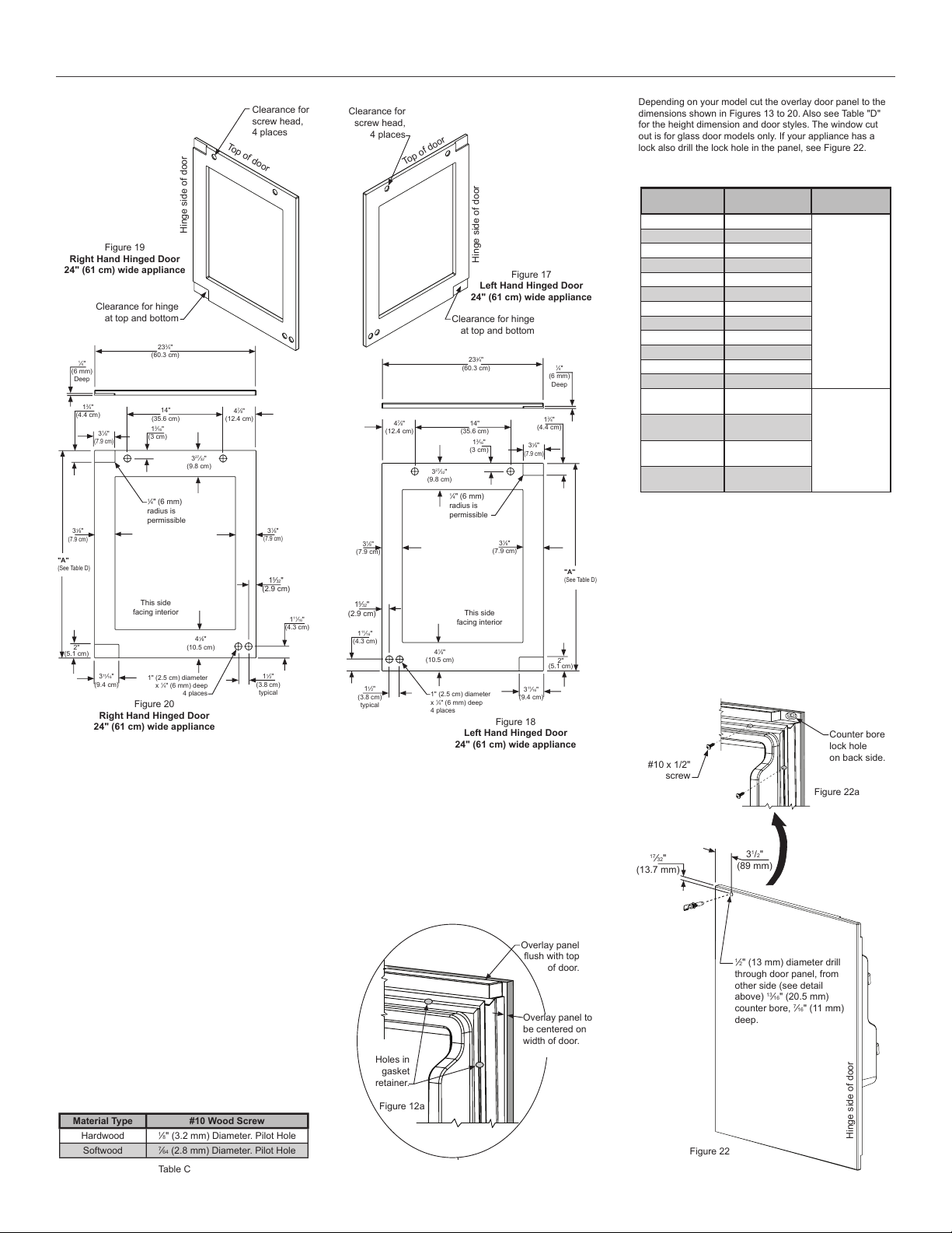
Step 3: Cut and drill the overlay panel
Depending on your model cut the overlay door panel to the
dimensions shown in Figures 13 to 20. Also see Table "D"
for the height dimension and door styles. The window cut
out is for glass door models only. If your appliance has a
lock also drill the lock hole in the panel, see Figure 22.
Overlay panel to
be centered on
width of door.
Figure 12a
Overlay panel
ush with top
of door.
Holes in
gasket
retainer.
Overlay panel to
be centered on
width of door.
17
⁄32"
(13.7 mm)
3
1
/2"
(89 mm)
1
⁄2" (13 mm) diameter drill
through door panel, from
other side (see detail
above) 13⁄16" (20.5 mm)
counter bore, 7⁄16" (11 mm)
deep.
Hinge side of door
Counter bore
lock hole
on back side.
Figure 22a
#10 x 1/2"
screw
Figure 22
Figure 20
Right Hand Hinged Door
24" (61 cm) wide appliance
Clearance for hinge
at top and bottom
233⁄4"
(60.3 cm)
1" (2.5 cm) diameter
x
1
⁄4" (6 mm) deep
4 places
4
7
⁄8"
(12.4 cm)
3
27
⁄32"
(9.8 cm)
1
3
⁄16"
(3 cm)
14"
(35.6 cm)
1
⁄4" (6 mm)
radius is
permissible
31⁄8"
(7.9 cm)
31⁄8"
(7.9 cm)
31⁄8"
(7.9 cm)
13⁄4"
(4.4 cm)
"A"
(See Table D)
2"
(5.1 cm)
3
11
⁄16"
(9.4 cm)
4
1
⁄8"
(10.5 cm)
1
1
⁄2"
(3.8 cm)
typical
1
⁄4"
(6 mm)
Deep
111⁄16"
(4.3 cm)
Hinge side of door
Top of door
Clearance for
screw head,
4 places
Figure 19
Right Hand Hinged Door
24" (61 cm) wide appliance
This side
facing interior
15⁄32"
(2.9 cm)
Figure 18
Left Hand Hinged Door
24" (61 cm) wide appliance
!
CAUTION
OVERLAY DOOR PANEL INSTALLATION
Weight of overlay door panel must not
exceed 15 pounds (6.8 kg) for a solid
door model or 10 pounds (4.5 kg) for a
glass door model.
Figure 20
Right Hand Hinged Door
24" (61 cm) wide appliance
233⁄4"
(60.3 cm)
1" (2.5 cm) diameter
x
1
⁄4" (6 mm) deep
4 places
4
7
⁄8"
(12.4 cm)
3
27
⁄32"
(9.8 cm)
1
3
⁄16"
(3 cm)
14"
(35.6 cm)
1
⁄4" (6 mm)
radius is
permissible
31⁄8"
(7.9 cm)
13⁄4"
(4.4 cm)
3
1
⁄8"
(7.9 cm)
3
1
⁄8"
(7.9 cm)
"A"
(See Table D)
2"
(5.1 cm)
3
11
⁄16"
(9.4 cm)
4
1
⁄8"
(10.5 cm)
1
1
⁄2"
(3.8 cm)
typical
1
⁄4"
(6 mm)
Deep
111⁄16"
(4.3 cm)
Hinge side of door
Top of door
Clearance for hinge
at top and bottom
Clearance for hinge
at top and bottom
Clearance for
screw head,
4 places
Figure 17
Left Hand Hinged Door
24" (61 cm) wide appliance
233⁄4"
(60.3 cm)
1" (2.5 cm) diameter
x
1
⁄4" (6 mm) deep
4 places
4
7
⁄8"
(12.4 cm)
3
27
⁄32"
(9.8 cm)
1
3
⁄16"
(3 cm)
14"
(35.6 cm)
1
⁄4" (6 mm)
radius is
permissible
31⁄8"
(7.9 cm)
31⁄8"
(7.9 cm)
31⁄8"
(7.9 cm)
13⁄4"
(4.4 cm)
"A"
(See Table D)
2"
(5.1 cm)
3
11
⁄16"
(9.4 cm)
4
1
⁄8"
(10.5 cm)
1
1
⁄2"
(3.8 cm)
typical
1
⁄4"
(6 mm)
Deep
111⁄16"
(4.3 cm)
Hinge side of door
Top of door
Clearance for
screw head,
4 places
Figure 19
Right Hand Hinged Door
24" (61 cm) wide appliance
This side
facing interior
This side
facing interior
15⁄32"
(2.9 cm)
15⁄32"
(2.9 cm)
MODEL
DOOR
DESCRIPTION DIM "A"
ML15RAP*RP Solid, Right Hand
ML15RAP*LP Solid, Left Hand
ML15BCF*RP Glass, Right Hand
ML15BCF*LP Glass, Left Hand
ML15BCP*RP Solid, Right Hand
ML15BCP*LP Solid, Left Hand
ML24RAP*RP Solid, Right Hand
ML24RAP*LP Solid, Left Hand
ML24BRF*RP Glass, Right Hand
ML24BRF*LP Glass, Left Hand
ML24BRP*RP Solid, Right Hand
ML24BRP*LP Solid, Left Hand
MA24BRF*RP
MA24BRF*LP
MA24RAP*RP
MA24RAP*LP
Glass, Right Hand
with Lock
Glass, Left Hand
with Lock
Solid, Right Hand
with Lock
Solid, Left Hand
with Lock
Table D
11
30
⁄32" (77.1 cm)
23
27
⁄32" (70.4 cm)
is to clamp the panel to the door so it cannot move while
drilling the screw pilot holes. Use bar clamps or "C" clamps
with pads on the clamping surfaces that will not mar the
panel or the door. The custom overlay panel should be
ush with the top of the door and centered along the width
of the door. See Figure 12a. Drill holes through the gasket
extrusion using the 10 holes as pilot holes. Use the drill
size from the chart in Table "C", being careful not to drill
through the front surface of the panel, drill no deeper than
1
⁄2" (12.7 mm) deep. If the overlay panel is thinner than
5
⁄8" (16 mm) thick shorter screws will have to be obtained.
Fasten the panel to the door with the 10 screws provided in
the literature pack. (See Figure 22a). Remove the clamps
and replace the gasket in the gasket extrusion channels of
the door. Some force may be required to seat the gasket
into the channels. Be sure the gasket corners are seated
properly.
For comprehensive installation instructions,
please visit www.marvelrefrigeration.com
 Loading...