

Page 1

EN Installation, Operation and maintenance Instructions
FR Instructions d’installation, d’utilisation et d’entretien
ES Instrucciones de instalación, operación y mantenimiento
Beer Dispensers
Distributeurs de bière
Dispensadores de
cerveza
ML24BN
ML24BS
ML24BT
Page 2
CONTENTS
Contents:
Safety information ...............................................................2
Unpacking your appliance ..................................................3
Warranty registration .....................................................3
Installing your appliance ......................................................4
Cabinet clearances .........................................................4
Leveling the appliance ....................................................4
Electrical connection ......................................................5
Installing the anti-tip device .................................................6
Product dimensions ML24BN ...........................................8
Product dimensions ML24BS and ML24BT ....................9
Product dimensions ML24BSSM and ML24BTSM ........10
Using your Electronic control ............................................11
Starting your appliance ..................................................11
Sleep mode ...................................................................11
Turning your appliance "ON" or "OFF" ..........................11
Adjusting the temperature .............................................12
Temperature mode ........................................................12
Control lock ....................................................................12
Alarms ...........................................................................12
Door ajar ...................................................................12
Power failure .............................................................13
Temperature alarm ....................................................13
Vacation mode ..............................................................13
Overlay door panel installation ........................................14
Using your beer dispenser.................................................19
Shelving .......................................................................19
Tap equipment and assembly......................................20
Externally mounting CO2 tank .......................................24
CO2 regulator ................................................................25
Drain kit ........................................................................26
Care and cleaning ............................................................26
Cleaning the drain sump ...............................................26
Tap cleaning kit .............................................................27
Faucet cleaning ............................................................27
Keg coupler cleaning ....................................................27
Front grille .....................................................................28
Cabinet .........................................................................28
Interior ..........................................................................28
Energy saving tips ...........................................................28
Door alignment .................................................................29
Obtaining service .............................................................29
Troubleshooting ................................................................30
Warranty ...........................................................................31
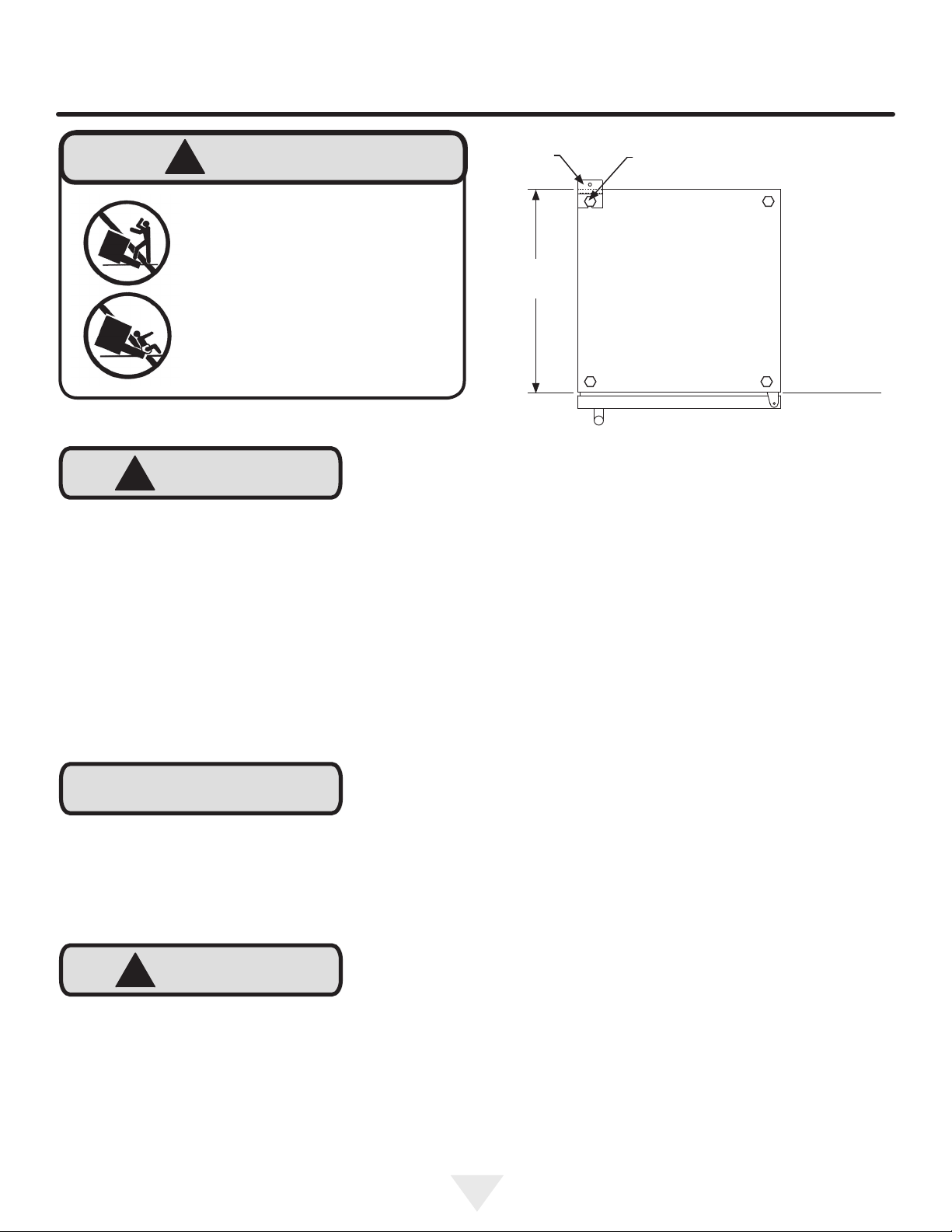
Important Safety Instructions
Warnings and safety instructions appearing in this guide
are not meant to cover all possible conditions and situations that may occur. Common sense, caution, and care
must be exercised when installing, maintaining, or operating this appliance.
Recognize Safety Symbols,
Words, and Labels.
!
WARNING
WARNING - You can be killed or seriously injured
if you do not follow these instructions.
!
CAUTION
CAUTION-Hazards or unsafe practices which could re-
sult in personal injury or property / product damage.
NOTE
NOTE-Important information to help assure a problem
free installation and operation.
State of California Proposition 65 Warnings:
WARNING: This product contains one or more chemicals
known to the State of California to cause cancer.
WARNING: This product contains one or more chemicals
known to the State of California to cause birth defects or
other reproductive harm..
is committed to building a quality product
in an environmentally friendly manner. Our processes are
tightly controlled and closely monitored. We have achieved
certications in ISO 9001 for quality assurance, ISO 14001
for environmental management, and OHSAS 18001 for occupational health and safety from Lloyd’s Register Quality
Assurance.
2
Page 3
UNPACKING YOUR APPLIANCE
!
WARNING
EXCESSIVE WEIGHT HAZARD
Use two or more people to move product.
Failure to do so can result in personal injury.
Remove Interior Packaging
Your appliance has been packed for shipment with all parts
that could be damaged by movement securely fastened.
Remove internal packing materials and any tape holding internal components in place. The owners manual is shipped
inside the product in a plastic bag along with the warranty
registration card, and other accessory items.
Important
Keep your carton and packaging until your appliance has
been thoroughly inspected and found to be in good condition. If there is damage, the packaging will be needed as
proof of damage in transit. Afterwards please dispose of all
items responsibly.
Warranty Registration
It is important you send in your warranty registration card
immediately after taking delivery of your appliance or you
can register online at www.agamarvel.com.
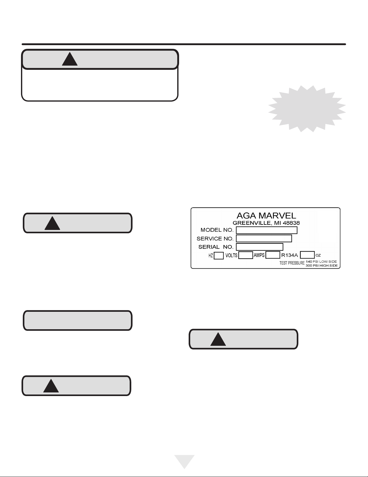
The following information will
be required when registering
your appliance.
Service Number
Serial Number
Date of Purchase
Dealer’s name and address
The service number and serial number can be found on the
serial plate which is located inside the cabinet on the left
side near the top. (See gure 1).
Online registration
available at
www.agamarvel.com
!
CAUTION
Dispose of the plastic bags which can be a suffocation
hazard.
Note to Customer
This merchandise was carefully packed and thoroughly
inspected before leaving our plant. Responsibility for its
safe delivery was assumed by the retailer upon acceptance
of the shipment. Claims for loss or damage sustained in
transit must be made to the retailer.
NOTE
DO NOT RETURN DAMAGED MERCHANDISE TO THE
MANUFACTURER - FILE THE CLAIM WITH THE
RETAILER.
!
CAUTION
If the appliance was shipped, handled, or stored in other
than an upright position for any period of time, allow the appliance to sit upright for a period of at least 24 hours before
plugging in. This will assure oil returns to the compressor.
Plugging the appliance in immediately may cause damage
to internal parts.
XXXXXXXXXXXX
XXXXXXXXXXXX
Figure 1
!
CAUTION
Help Prevent Tragedies
Child entrapment and suffocation are not problems of the
past. Junked or abandoned refrigerators are still dangerous
- even if they sit out for "just a few days".
If you are getting rid of your old refrigerator, please follow
the instructions below to help prevent accidents.
Before you throw away your old refrigerator or freezer:
• Take off the doors or remove the drawers.
• Leave the shelves in place so children may not easily
climb inside.
3
Page 4
INSTALLING YOUR APPLIANCE
Select Location
The proper location will ensure peak performance of your
appliance. We recommend a location where the unit will
be out of direct sunlight and away from heat sources. To
ensure your product performs to specications, the recommended installation location temperature range is from 55
to 100°F (13 to 38°C).
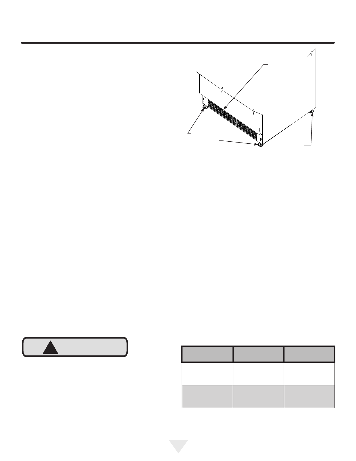
Cabinet Clearance
Ventilation is required from the bottom front of the appliance. Keep this area open and clear of any obstructions.
Adjacent cabinets and counter top can be installed around
the appliance as long as the front grille remains unobstructed. Overlay door models with articulated hinges are
intended for built-in applications only.
Front Grille,
keep this area
open.
Front Leveling
Legs
Figure 2
Rear
Leveling
Legs
Leveling Legs
Adjustable legs at the front and rear corners of the appli-
ance should be set so the unit is rmly positioned on the
oor and level from side to side and front to back. The over-
all height of your Marvel appliance may be adjusted higher
(by turning the leveling leg out, CCW) and lower (by turning
the leveling leg in, CW) dimensions as shown in Table "A".
!
CAUTION
Front Grille
Do not obstruct the front grille. The openings within the
front grille allow air to ow through the condenser heat exchanger. Restrictions to this air ow will result in increased
energy usage and loss of cooling capacity. For this reason
it is important this area not be obstructed and the grille
openings kept clean. AGA MARVEL does not recommend
the use of a custom made grille as air ow may be restricted. (See Figure 2).
To adjust the leveling legs, place the appliance on a solid
surface and protect the oor beneath the legs to avoid
scratching the oor. With the assistance of another person,
lean the appliance back to access the front leveling legs.
Raise or lower the legs to the required dimension by turning
the legs. Repeat this process for the rear by tilting the appliance forward using caution. On a level surface check the
appliance for levelness and adjust accordingly.
The front grille screws may be loosened and the grille adjusted to the desired height. When adjustment is complete
tighten the two front grille screws. (See Figure 3).
Model
ML24BNS
ML24BSS
ML24BTS
ML24BNP
ML24BSP
ML24BTP
Minimum
Height
33 3⁄4" (85.7 cm) 34 3⁄4" (88.3 cm)
34" (86.4 cm) 35" (88.9 cm)
Table A
Maximum
Height
4
Page 5
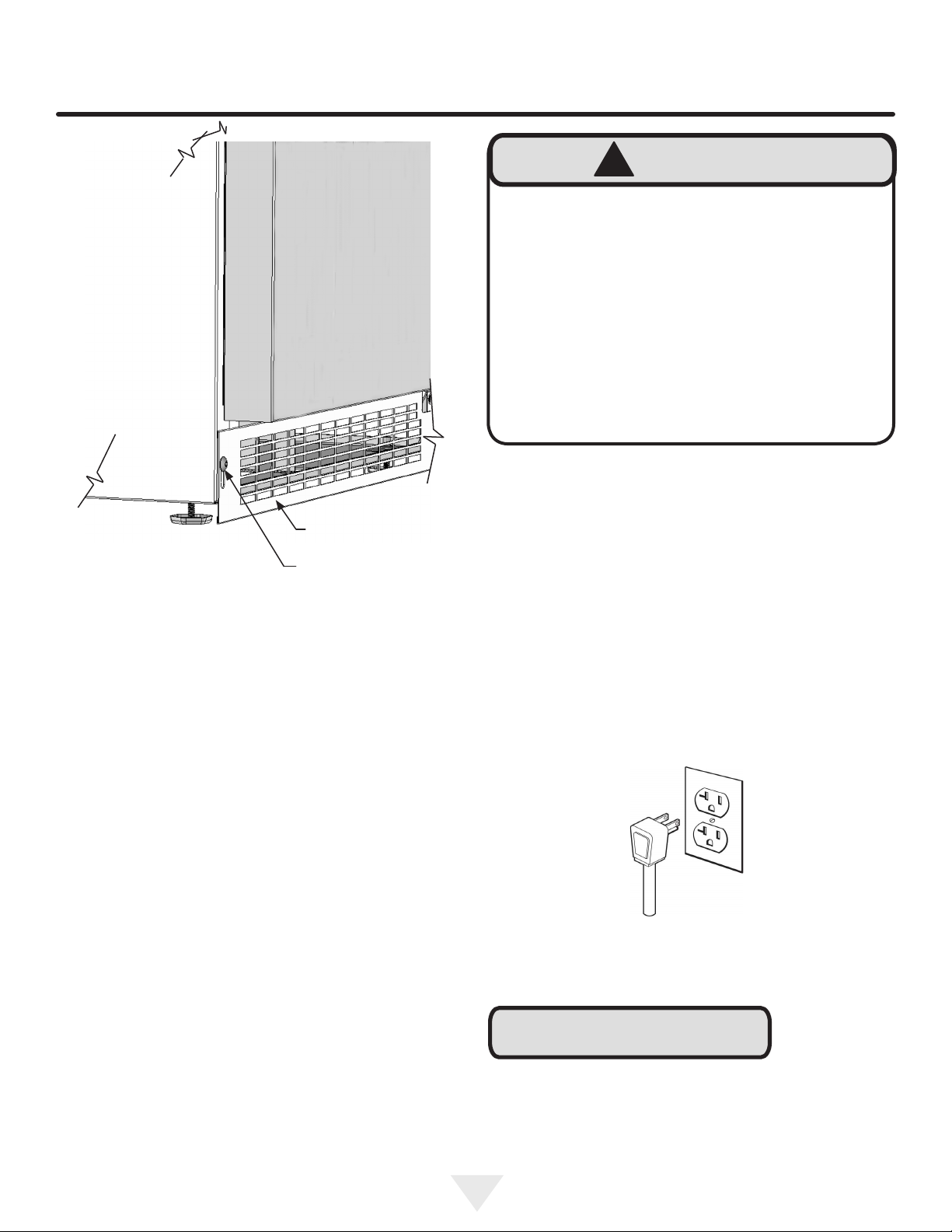
INSTALLING YOUR APPLIANCE
!
Electrical Shock Hazard
• Do not use an extension cord with this appliance.
They can be hazardous and can degrade product
performance.
• This appliance should not, under any circumstances, be installed to an un-grounded electrical supply.
• Do not remove the grounding prong from the power
cord.
• Do not use an adapter.
• Do not splash or spray water from a hose on the
appliance. Doing so may cause an electrical shock,
which may result in severe injury or death.
Electrical Connection
A grounded 115 volt, 15 amp dedicated circuit is required.
WARNING
Figure 3
Front grille
Front grille screw
This product is factory equipped with a power supply
cord that has a three-pronged, grounded plug. It must be
plugged into a mating grounding type receptacle in accordance with the National Electrical Code and applicable lo-
cal codes and ordinances (see Figure 4). If the circuit does
not have a grounding type receptacle, it is the responsibility
and obligation of the customer to provide the proper power
supply. The third ground prong should not, under any circumstances, be cut or removed.
Figure 4
NOTE
Ground Fault Circuit Interrupters (GFCI) are prone to nuisance tripping which will cause the appliance to shut down.
GFCI’s are generally not used on circuits with power equipment that must run unattended for long periods of time, unless required to meet local building codes and ordinances.
5
Page 6
INSTALLING THE ANTI TIP DEVICE
!
WARNING
• ALL APPLIANCES CAN TIP
RESULTING IN INJURY.
Anti-Tip
Bracket
Leveling Leg
• INSTALL THE ANTI-TIP
BRACKET PACKED WITH
THE APPLIANCE.
• FOLLOW THE INSTRUCTIONS BELOW
Anti-Tip Device
!
CAUTION
If your beer dispenser is not located under a counter top
(free standing), you must use an anti-tip device installed
as per these instructions. If the beer dispenser is removed
from its location for any reason, make sure that the device
is properly engaged when you push the beer dispenser
back into the original location. If the device is not properly
engaged, there is a risk of the beer dispenser tipping over,
with the potential for property damage or personal injury.
211⁄2"
(54.6 cm)
Bottom View of
Beer dispenser
Front of cabinet
Figure 5
Step by step instructions for locating the
position of the bracket:
1) Decide where you want to place the beer dispenser.
Slide it into place, being careful not to damage the oor,
leaving 1" (2.5 cm) of clearance from the rear wall to allow
room for the anti-tip bracket.
2) Raise the rear leveling legs approximately 1⁄4" (6 mm) to
allow engagement with the anti-tip bracket. Level the unit
by adjusting all the leveling legs as required. Turning the
leveling leg counterclockwise will raise the unit and clockwise will lower the unit.
NOTE
If installing on a concrete oor, concrete fasteners are
required, (not included with the anti-tip kit).
!
CAUTION
Any nished ooring should be protected with appropriate
material to avoid damage when moving the unit.
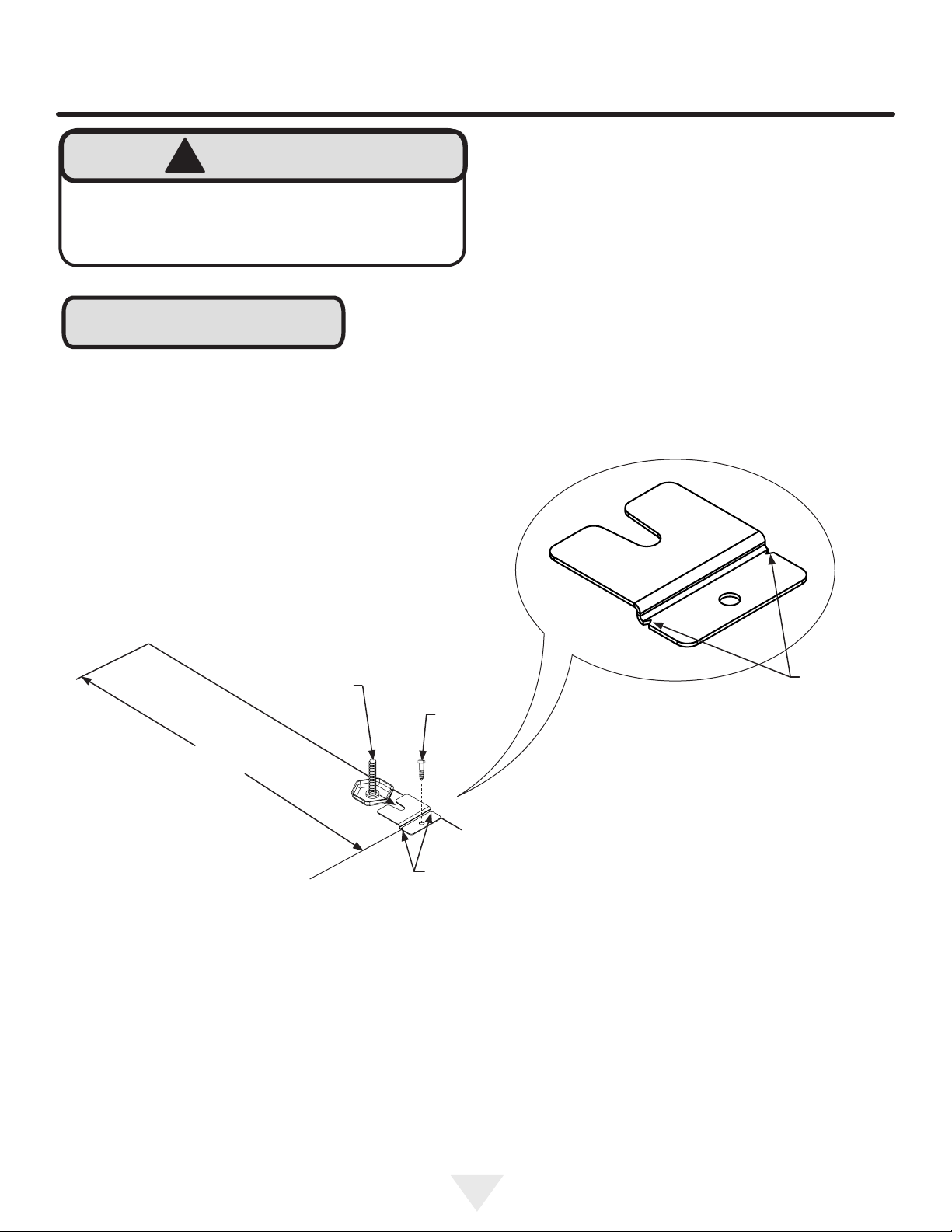
Floor Mount Installation
The anti-tip bracket is to be located on the oor in the left or
right rear corner of the beer dispenser as shown in
Figure 5.
3) Make sure the beer dispenser is in the desired location, then mark on the oor the rear and side corner of the
cabinet where the anti-tip bracket will be installed. If the
installation does not allow marking the rear corner of the
cabinet, then make temporary lines on the oor marking
the front corner of the cabinet, excluding the door. Slide
the beer dispenser out of the way. From the temporary line
extend the sidewall line back 211⁄2" (54.6 cm) as shown in
Figure 6.
4) Align the anti-tip bracket to the marks on the oor so
the side of the bracket lines up with the side of the cabinet
mark, and the "V" notches on the anti-tip bracket line up
with the end of the 211⁄2" (54.6 cm) line (Rear of cabinet
line).
5) Fasten the anti-tip bracket to the oor using the supplied
screw. (See Figure 6).
6) Slide the cabinet back into position, making sure the
rear cabinet leveling leg slides under the anti-tip bracket
engaging the slot.
6
Page 7
INSTALLING THE ANTI TIP DEVICE
!
WARNING
TIP OVER HAZARD: One of the rear cabinet
leveling legs must be engaged under an anti-tip
bracket.
NOTE
When the oor mounted anti-tip bracket is used the minimum adjusted height of the cabinet is increased by
3
⁄8" (9 mm).
Front of cabinet line
Side of cabinet line
211⁄2"
(54.6 cm)
Figure 6
Rear Leveling leg
Rear of cabinet line
Screw
"V" notches
in bracket
Figure 6a
"V" notches
in bracket
7
Page 8
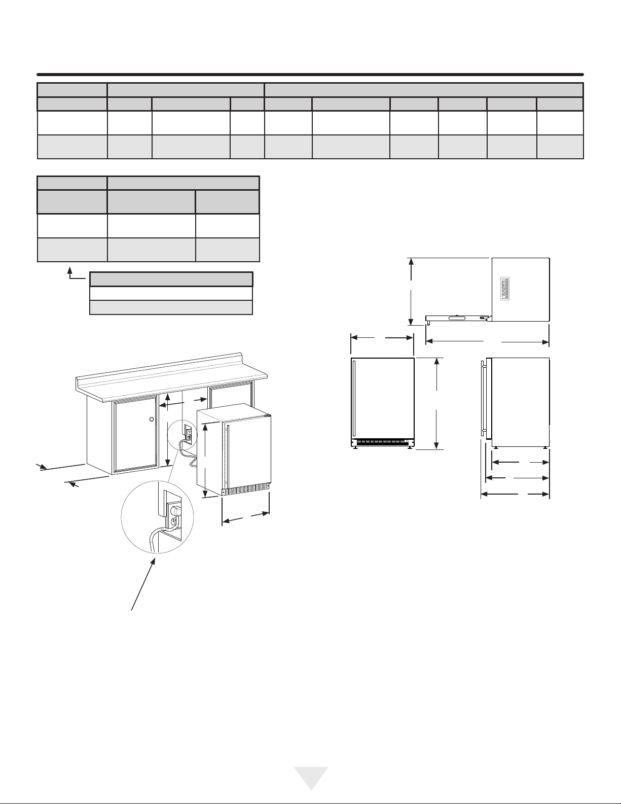
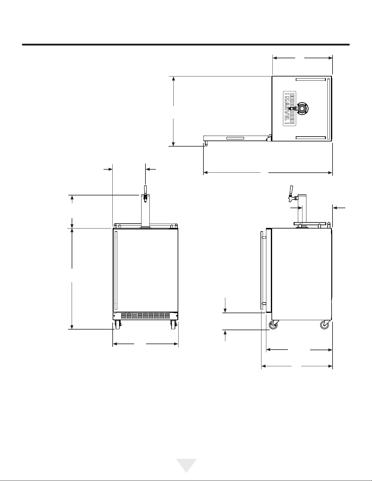
PRODUCT DIMENSIONS ML24BN
ROUGH-IN OPENING DIMENSIONS CABINET DIMENSIONS
MODEL "A" "B" "C" "D" "E" "F" "G" "H" "J"
ML24BN(S)
ML24BN(P)
MODEL
ML24BN(S) 115V/60Hz/15A
ML24BN(P) 115V/60Hz/15A
24"
(61 cm)
24"
(61 cm)
ELECTRICAL
REQUIREMENTS#
**34" to 35"
(86.4 to 88.9 cm)
**341⁄4" to 351⁄4"
(87 to 89.5 cm)
PRODUCT DATA
PRODUCT
WEIGHT
140 lbs
(63.6 kg)
140 lbs
(63.6 kg)
*
*
237⁄8"
(60.7 cm)
237⁄8"
(60.7 cm)
333⁄4" to 343⁄4"
(85.7 to 88.3 cm)
34" to 35"
(86.4 to 88.9 cm)
2323⁄32"
(60.2 cm)
227⁄8"
(58.1 cm)
2521⁄32"
(65.2 cm)
-
4613⁄32"
(117.9 cm)
461⁄2"
(118.1 cm)
(65.2 cm)
(58.7 cm)
2511⁄16"
231⁄8"
"C"
DOOR STYLE
(S) Solid Door
(P) Solid Overlay Door (no handle)
"A"
"B"
Figure 7a
"E"
"D"
Figure 7
"D"
"J"
"E"
Figure 8
"H"
211⁄2"
(54.6cm)
"F"
"G"
If necessary to gain clearance inside
the rough-in opening a hole can be cut
through the adjacent cabinet and the
power cord routed through this hole to a
power outlet. Another way to increase the
available opening depth is to recess the
power outlet into the rear wall 1" (2.5 cm)
to gain the thickness of the power cord
plug.
* Depth dimension of rough-in opening may vary depending on each individual installation. To recess entire door "F"
dimension plus 1" (2.5 cm) for thickness of power cord plug
is required.
** Minimum rough-in opening required is to be larger than
the adjusted height of the cabinet.
# A grounded 15 amp dedicated circuit is required. Follow
all local building codes when installing electrical and appliance.
8
Page 9
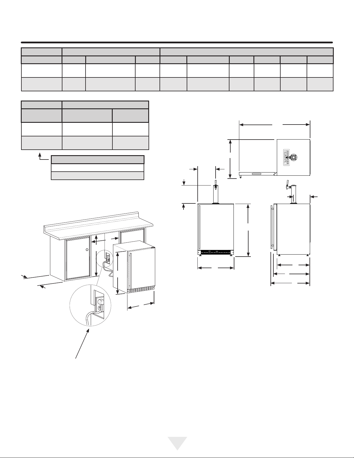
PRODUCT DIMENSIONS ML24BS AND ML24BT
ROUGH-IN OPENING DIMENSIONS CABINET DIMENSIONS
MODEL "A" "B" "C" "D" "E" "F" "G" "H" "J"
ML24BS(S)
ML24BT(S)
ML24BS(P)
ML24BT(P)
MODEL
ML24BS(S)
ML24BT(S)
ML24BS(P)
ML24BT(P)
24"
(61 cm)
24"
(61 cm)
ELECTRICAL
REQUIREMENTS#
115V/60Hz/15A
115V/60Hz/15A
**34" to 35"
(86.4 to 88.9 cm)
**341⁄4" to 351⁄4"
(87 to 89.5 cm)
PRODUCT DATA
PRODUCT
WEIGHT
140 lbs
(63.6 kg)
140 lbs
(63.6 kg)
*
*
237⁄8"
(60.7 cm)
237⁄8"
(60.7 cm)
333⁄4" to 343⁄4"
(85.7 to 88.3 cm)
34" to 35"
(86.4 to 88.9 cm)
2323⁄32"
(60.2 cm)
227⁄8"
(58.1 cm)
2521⁄32"
(65.2 cm)
-
(117.9 cm)
(118.1 cm)
"H"
4613⁄32"
(65.2 cm)
461⁄2"
(58.7 cm)
2511⁄16"
231⁄8"
"C"
DOOR STYLE
(S) Solid Door
(P) Solid Overlay Door (no handle)
"A"
"B"
Figure 9a
"E"
"D"
Figure 9
1115⁄16"
(30.3 cm)
121⁄4"
(31.1 cm)
"D"
"J"
"E"
Figure 10
11"
(27.9 cm)
211⁄2"
(54.6 cm)
"F"
"G"
If necessary to gain clearance inside
the rough-in opening a hole can be cut
through the adjacent cabinet and the
power cord routed through this hole to a
power outlet. Another way to increase the
available opening depth is to recess the
power outlet into the rear wall 1" (2.5 cm)
to gain the thickness of the power cord
plug.
* Depth dimension of rough-in opening may vary depending on each individual installation. To recess entire door "F"
dimension plus 1" (2.5 cm) for thickness of power cord plug
is required.
** Minimum rough-in opening required is to be larger than
the adjusted height of the cabinet.
# A grounded 15 amp dedicated circuit is required. Follow
all local building codes when installing electrical and appliance.
9
Page 10
PRODUCT DIMENSIONS ML24BSSM AND ML24BTSM
Single dispense tower shown
121⁄4"
(31.1 cm)
1115⁄16"
(30.3 cm)
211⁄2"
(54.6 cm)
2511⁄16"
(65.2 cm)
4613⁄32"
(117.9 cm)
11"
(27.9 cm)
3613⁄16"
(93.5 cm)
237⁄8"
(60.7 cm)
Electrical Requirements: A grounded 115 volt, 15 amp dedi-
cated circuit is required.
Power outlet can be located in the back wall behind unit.
Follow all local building codes when installing electrical and
unit. Product weight = 150 lbs. (68.2 kg.)
(15.9 cm)
Figure 11
61⁄4"
2323⁄32"
(60.2 cm)
2521⁄32"
(65.2 cm)
10
Page 11

USING YOUR ELECTRONIC CONTROL
Temp
Minus
keypad
On/Off
keypad
Temp
Plus
keypad
Display Area
Figure 12 Electronic single zone
Power Failure
ALARM RESET
Starting your appliance:
Plug the appliance power cord into a 115 volt wall outlet.
Your appliance is shipped from the factory in the "On" position and will begin start-up of cooling as soon as power is
supplied. If the appliance does not start, conrm that the
wall outlet has power, and that the control is in the "On"
position, (See "Turning your appliance On and Off" below).
Lock
keypad
System Status
indicators
control
To wake the display press any keypad. A conrm tone will
sound, and the current storage compartment temperature
will be displayed.
The control display is covered with a clear plastic lm. This
lm may be removed by carefully lifting the lm at a corner.
On initial power up, the control display will indicate a
"Power Failure" alarm. This is a normal condition as the appliance was powered-up at the factory for quality inspection
and then removed from power. A momentary press of the
"On/Off" keypad will reset this alarm condition. (See Alarms
section on page 12).
Sleep mode:
If no keypads are pressed for 60 seconds, the display will
enter sleep mode to conserve power. The control panel will
go dark with the exception of the system status "OK" indicator which will remain enabled. Alarm conditions will wake
the display, (see alarms on page 12).
The sleep mode can be disabled if you prefer to have the
display on continuously. Press and hold the "Lock" keypad until the display goes past "Loc" and reads "nSL". To
enable the sleep mode, repeat the instruction, again going
past "Loc" until the display reads "SLP".
Turning your appliance ON and OFF:
If the appliance is "On", (and out of sleep mode) the temperature will be shown in the display area of the control.
To turn the appliance "Off", press and hold the "On/Off"
keypad for 4-seconds. "OFF" will now be displayed on the
control.
To make the following changes to the control settings
(turning the appliance ON/OFF, adjusting the temperature, and activating vacation mode), the control must
be awake.
To turn the appliance "On", press and hold the "On/Off"
keypad for 4-seconds.
11
Page 12

USING YOUR ELECTRONIC CONTROL
Adjusting the temperature:
To set or check the set-point temperature (with the control
out of sleep mode), press the "-" or "+" keypads. "SET" will
be indicated on the user interface panel and the current
set-point temperature will display and ash. Subsequent
presses of the "-" or "+" keypads will adjust the temperature
colder or warmer respectively. When you have reached
your desired set-point temperature, press the "On/Off" keypad to accept, or do nothing and the "Set" mode will timeout in 10-seconds accepting the displayed temperature as
the new set-point.
The available set-point temperature range for your ap-
pliance is 34°F (1.2°C) to 46°F (7.9°C). If you attempt to
adjust the temperature outside of this range you will receive
an audible notication.
!
CAUTION
If you are using the appliance as a refrigerator for perishable foods, the set-point temperature should be set be-
tween 34°F and 42° F (1.2° C and 5.7° C).
When initially loading your product with warm contents, it
may take up to 48-hours for the storage compartment temperature to stabilize.
Temperature mode:
The temperature mode is preset from the factory in Fahren-
heit (°F) but you have the option to change it to Centigrade
(°C). To change the mode, press and hold the "-" keypad,
while pressing the "+" keypad, then release the "-" keypad.
The temperature will now be displayed in Centigrade (°C).
Repeat the procedure to change the temperature mode
back to Fahrenheit (°F).
Control lock:
The control panel can be locked to avoid unintentional
changes. To lock the control, press and hold the "Lock" key-
pad until the display reads "Loc" then release your nger
from the keypad. The lock icon will ash 3-times and then
continuously illuminate. When the control panel is locked,
only the Lock keypad, System Status OK indicator , and
the Alarm indicator are active. To un-lock the control panel,
repeat this instruction until the display reads "nLc".
When making temperature set-point changes, it may take
up to 24-hours for the stored contents to stabilize at your
new set-point temperature.
Factors that affect the storage compartment stabilized
temperature:
• Changes to temperature setting.
• Room temperature changes.
• Temperature of stored contents.
- Loading warm contents.
- Cold content load will delay the change to a warmer
set-point temperature.
- Warm content load will delay the change to a colder
set-point temperature.
• Usage, (number and duration of the door openings).
• Installation of the appliance in direct sunlight or next to
a heat source.
Alarms:
The control will alert you to conditions that could adversely
affect the performance of the appliance.
Door Ajar
ALARM RESET
• Door ajar - If the door is open, or not closed prop-
erly, for more than 5-minutes the System Status OK
indicator will turn-off, the "Door Ajar" indicator will ash,
and a tone will sound every 60 seconds. Additionally,
an "ALARM RESET" indicator will be displayed below
the "On/Off" keypad. This alarm condition can be reset
by closing the door or momentarily pressing the "On/
Off" keypad, (i.e.-if you are cleaning the storage com-
partment, etc.). The alarm will recur in 5-minutes if the
alarm condition persists.
12
Page 13

USING YOUR ELECTRONIC CONTROL
Power Failure
• Power failure - If power to the appliance is inter-
rupted the System Status indicator will turn-off and
the "Power Failure" indicator will ash. Additionally, an
"ALARM RESET" indicator will be displayed below the
"On/Off" keypad. No audible tone will sound. This alarm
condition can be reset by momentarily pressing the
"On/Off" keypad. If this alarm occurs, it is recommended that you check the condition of any perishables,
even if the appliance is operating normally and the temperature has recovered, as prolonged power outages
could result in excessive temperature excursions which
may spoil perishables.
ALARM RESET
Vacation mode:
This operating mode can be used to save energy during
high cost energy periods, or when you won't be using your
appliance for an extended period of time by disabling the
lights, alarm tones, and keypad entry tones. Vacation mode
also serves as a Sabbath mode, disabling functions and
its controls in accordance with the weekly Sabbath and
religious holidays observed within the Orthodox Jewish
community. When used as Sabbath mode, you may open
or close the door at any time to access contents without
concern of directly turning on or off any lights, digital readouts, solenoids, fans, valves, compressor, icons, tones, or
alarms.
When activated, the display, alarm indicators and tones,
keypad touch tones, interior lights, and all options are disabled. All keypad functions are disabled, with the exception
of the "On/Off" keypad which is required to exit Vacationmode. Storage compartment temperatures are monitored
and controlled at the settings prior to entering Vacation
mode.
Temp
ALARM RESET
• Temperature alarm - If the storage compartment
temperature exceeds 10°F from set-point for more than
a 1-hour duration, the System Status indicator will turn
off, the "Temp" indicator will ash, and an audible tone
will sound every 60-seconds. Additionally, an "ALARM
RESET" indicator will be displayed below the "On/Off"
keypad. This alarm condition can be reset by momentarily pressing the "On/Off" keypad. If this alarm occurs
it is recommended that you check the condition of your
stored contents, even though the appliance is operating
normally and the temperature has recovered, as prolonged temperature excursions could spoil perishables.
Door Ajar
NOTE
Multiple alarms are possible, i.e.- "Door Ajar" for a prolonged period may trigger a "Temp" alarm, in which case
both "Door Ajar" and "Temp" indicators will activate.
Temp
To enter Vacation Mode (with the control out of sleep
mode), press and hold the "On/Off" keypad until the display
goes past "OFF" and reads "VAC". The display will ash
"VAC" 3-times to acknowledge your request, then will
display "VAC" continuously until Vacation mode is exited.
A power outage will not exit Vacation mode, exiting can
only be accomplished manually. To exit Vacation mode and
return to normal operation, press and hold the "On/Off"
keypad until the control displays the temperature.
13
Page 14

OVERLAY DOOR PANEL INSTALLATION
If you purchased an overlay panel model, your unit is
equipped with articulated hinges to allow fully integrated
built-in installations. Custom panel thicknesses of 5⁄8" (15
mm) and 3⁄4" (18 mm) are accommodated.
!
CAUTION
It is important to use the factory provided grille that came
with the product to assure proper air ow is maintained
through the condenser. The use of a custom grille is not
recommended and will void the warranty.
!
WARNING
!
WARNING
Use extreme caution with the articulated hinges. The
hinge is self closing and many pinch points exist prior
to built-in installation. Do not remove the cabinet "Z"
bracket from the top of the cabinet.
Loosen (do not remove)
these 2 phillips head
screws on the top and
bottom hinges
Overlay panel models are designed for use with built-
in installations only. Use in freestanding installations
could result in personal injury.
Step 1: Removing the Door
With a phillips screwdriver remove the screw and "P" clamp
from the bottom of the door near the hinge. See Figure 13b.
Disconnect the door wire harness by pressing and holding
down the locking tab on the wire connector and pulling the
connector apart. See Figure 14.
Open the door and loosen the screws holding the hinges to
the cabinet (2 at the top and 2 at the bottom hinge). Do not
remove the screws but loosen them enough so the hinges
can be slipped off of the screws when sliding the door to
the side.
!
WARNING
The articulated hinges have many pinch points. Carefully close / collapse the hinges as soon as the door is
removed from the cabinet.
Cabinet
Figure 13a
"Z" Bracket
Figure 13
"P" clamp
and screw
With a helper, and being careful not to scratch the cabinet
or the door, slide the door to the side about 1⁄2 inch and
remove the hinges and door from the unit.
14
Figure 13b
Bottom of
door
Wire connector
see Figure 14
Page 15

OVERLAY DOOR PANEL INSTALLATION
Press and hold down this
tab on the wire connector
and pull the connector apart.
Figure 14
Step 2: Remove the door gasket
With the door laying on a at surface and starting at a
corner of the door remove the magnetic door gasket from
the interior side of the door, see Figure 15. Set the gasket
aside on a at surface.
There are 10 holes in the gasket retainer extrusions, (3 on
each side and 2 at the top and bottom which are used to
fasten the panel to the front of the door. The screws are
provided in the literature pack.
Holes in
gasket
retainer.
Figure 15a
Overlay panel
ush with top
of door.
Overlay panel to
be centered on
width of door.
Magnetic Gasket
remove starting at a
corner, grasp and pull
away from the door.
Figure 15
Step 3: Cut and drill the overlay panel
Depending on your model cut the overlay door panel to the
dimensions shown in Figures 16 and 17 for a left hand door
model or Figures 18 and 19 for a right hand door model.
15
Page 16

Clearance for
screw head,
4 places
OVERLAY DOOR PANEL INSTALLATION
Clearance for hinge
Top of door
at top and bottom
Clearance
for hinge
at top and
bottom
Top of door
Clearance for
screw head,
4 places
Figure 16
Left Hand Hinged Door
24" (61 cm) wide appliance
47⁄8"
(12.4 cm)
(35.6 cm)
1
⁄4" (6 mm)
radius is
permissible
233⁄4"
(60.3 cm)
14"
13⁄16"
(3 cm)
(4.4 cm)
31⁄8"
(7.9 cm)
13⁄4"
Hinge side of door
1
⁄4"
(6 mm)
Deep
1
⁄4"
(6 mm)
Deep
13⁄4"
(4.4 cm)
Hinge side of door
31⁄8"
(7.9 cm)
1" (2.5 cm) diameter
x 1⁄4" (6 mm) deep
233⁄4"
(60.3 cm)
14"
(35.6 cm)
13⁄16"
(3 cm)
4 places
Figure 18
Right Hand Hinged Door
24" (61 cm) wide appliance
47⁄8"
(12.4 cm)
15⁄32"
(2.9 cm)
111⁄16"
(4.3 cm)
11⁄2"
(3.8 cm)
typical
This side
facing
interior
1" (2.5 cm) diameter
x 1⁄4" (6 mm) deep
4 places
311⁄16"
(9.4 cm)
Figure 17
Left Hand Hinged Door
24" (61 cm) wide appliance
(77.1 cm)
2"
(5.1 cm)
3011⁄32"
16
3011⁄32"
(77.1 cm)
2"
(5.1 cm)
311⁄16"
(9.4 cm)
This side
facing
interior
1
⁄4" (6 mm)
radius is
permissible
Figure 19
Right Hand Hinged Door
24" (61 cm) wide appliance
15⁄32"
(2.9 cm)
111⁄16"
(4.3 cm)
11⁄2"
(3.8 cm)
typical
Page 17

OVERLAY DOOR PANEL INSTALLATION
!
CAUTION
Weight of overlay door panel must not
exceed 15 pounds (6.8 kg) for a solid
door model.
Step 4: Assemble the panel to the door
The preferred method of attaching the panel to the door
is to clamp the panel to the door so it cannot move while
drilling the screw pilot holes. Use bar clamps or "C" clamps
with pads on the clamping surfaces that will not mar the
panel or the door. The custom overlay panel should be
ush with the top of the door and centered along the width
of the door. See Figure 15a. Drill holes through the gasket
extrusion using the 10 holes as pilot holes. Use the drill
size from the chart in Table "B", being careful not to drill
through the front surface of the panel, drill no deeper than
1
⁄2" (12.7 mm) deep. If the overlay panel is thinner than
5
⁄8" (16 mm) thick shorter screws will have to be obtained.
Fasten the panel to the door with the 10 screws provided
in the literature pack. (See Figure 20). Remove the clamps
and replace the gasket in the gasket extrusion channels of
the door. Some force may be required to seat the gasket
into the channels. Be sure the gasket corners are seated
properly.
#10 x 1/2"
screw
Figure 20
Material Type #10 Wood Screw
Hardwood
Softwood
1
⁄8" (3.2 mm) Diameter. Pilot Hole
7
⁄64 (2.8 mm) Diameter. Pilot Hole
Table B
Step 5: Install the door
Carefully open the top and bottom hinges on the door being
careful as there are many pinch points. Place the hinges
over the 4 screws in the cabinet, 2 at the top and 2 at the
bottom and slide the door into position. Tighten the 4 hinge
screws with a phillips screwdriver. (See Figures 13 and
13a). Place wire harness from the grille and mount to the
bottom of the door with the screw and "P" clamp removed
in step 1. (See Figure 13b). Reconnect the wire harness,
(See Figure 14).
17
Page 18

OVERLAY DOOR PANEL INSTALLATION
Step 6: Secure the cabinet
Use the #8 x 3⁄4" black screws from the literature pack to
secure the counter top to the cabinet top through the holes
in the cabinet "Z" bracket.
Cabinet
"Z" bracket
#8 x 3⁄4" black
screw (3 places)
Figure 21
18
Page 19

USING YOUR BEER DISPENSER
Shelving
The unit is shipped with the (2) shelves taped in place in
the upper and the lower shelf positions. Remove them from
the refrigerator and arrange them as follows when setting
up your unit.
Figure 22
Two shelves
If you are using a quarter barrel of beer, you can add shelf
space for keeping your mugs chilled. The quarter barrel
must set on the oor, it cannot t on the shelf, see
Figure 24. Be sure the white oor plate is in the bottom of
the interior compartment before positioning the barrel.
Installed upper
shelf above
barrel
If you are not serving beer on tap, your keg dispenser can
be used as a refrigerator by placing both shelves on the
mounting brackets as shown in Figure 23. The shelves are
marked upper and lower, The upper shelf should be placed
in the top shelf position and the shelf marked lower should
be placed in the bottom shelf position.
!
CAUTION
If you are using the appliance as a refrigerator for perishable foods, the set-point temperature should be set
between 34°F and 42° F (1.2° C and 5.7° C).
Two shelves
installed
Quarter barrel
If you are using a half barrel (keg) or (2) 1/6 barrels, place
the two shelves on the right side of the keg dispenser on
the two mounting hooks for storage. (See Figure 25). Be
sure the white oor plate is in the bottom of the interior
compartment before positioning the barrel(s).
Figure 24
Stored lower shelf
White oor plate
Stored upper and
lower shelves
on side
Figure 23
Half barrel (keg)
19
Figure 25
White oor plate
Page 20

USING YOUR BEER DISPENSER
This beer dispensing unit will support one half (1⁄2) barrel
or one quarter (1⁄4) barrel. The double draft tower units can
support two sixth (1⁄6) barrels of beer. See chart below for
quantity of beer in each barrel size.
Barrel Sizes
1/6 barrel 1/4 Barrel 1/2 Barrel
Height
Diameter
Gallons 5.23 7.75 15.5
#12 ounce
Glasses
235⁄16"
(59.2 cm)
91⁄4"
(23.5 cm)
53 82 163
Table C
1413⁄16"
(37.6 cm)
17"
(43.2 cm)
235⁄16"
(59.2 cm)
17" to 171⁄4"
(43.2 to 43 cm)
Tools required for installation:
Flat bladed screwdriver
Phillips screwdriver
Pliers
Adjustable wrench or a 11⁄8" open end wrench
1⁄2" open end wrench
!
WARNING
CO2 can be dangerous. If it becomes difcult to
breathe and/or your head starts to ache, a high
concentration of carbon dioxide may be present.
Leave the area immediately.
• The CO2 tank must always be connected to the
regulator. Never connect the tank to the keg.
• The CO2 tank must be securely mounted in the
upright position. Secure it with the chain provided.
• Never drop or throw the CO2 tank.
• Keep the CO2 tank away from heat.
• Ventilate the area after a CO2 leak.
Keg Size
5 gallon Corny 15 to 22
1/6 barrel 14 to 21
1/4 Barrel 10 to 14
1/2 Barrel 5 to 7
Table D
#of kegs per
5 pound CO2 Tank
Tap Equipment and Assembly
Your dispensing kit includes the following parts:
Polished stainless steel tower with clear beer line (single
or double dispense)
Tower Gasket
Phillips oval head screws
Knob for Tower (Faucet Handle)
Keg coupler(s)
CO2 regulator with red gas line(s) attached
Empty 5 pound CO2 tank
Plastic clamp(s) large and small
Faucet wrench
1. Remove shelving and packaged components from the
interior of the refrigerator before beginning the assembly process.
2. Take your empty 5 pound CO2 tank to your local gas
supply dealer to be lled. You can usually nd them in
your "yellow pages" under "Welding Supply" or "Fire
Protection". One 5 pound tank can process many kegs
(see table "D") Your dealer should supply you with a
plastic washer every time the tank is lled.
3. Tower mounting (if you are installing the unit under a
counter skip to step 4). If you are mounting the tower
directly to the top of the refrigerator, rst remove the
four screws from the top of the refrigerator. Feed the
clear beer line through the tower gasket and the large
hole in the refrigerator top. Align the 4 holes in the
tower with the 4 holes in the refrigerator top and secure
the tower with the 4 screws removed previously. Skip to
step 5.
20
Page 21

USING YOUR BEER DISPENSER
Single Dispense Tower Kit
Connect to ,etc........
A A
Single
Dispense
Tower
Figure 26
Figure 27
Hose clamps
use for connections
A
and
A
C
Double Dispense Tower Kit
Connect to ,etc........
A A
Figure 31
Double
Dispense
Tower
Figure 32
Hose clamps
use for connections
A
A
A
Figure 33
A
and
C
C
Keg
Coupler
C
Regulator
Figure 29
with red
airline
B
A
C
B
5 Pound
CO2 Tank
Figure 30
Figure 28
Keg
Coupler
C
Regulator
with red
airline
A
C
Figure 36
Keg
Coupler
Figure 34
B
B
5 Pound
CO2 Tank
Figure 35
C
21
Page 22

USING YOUR BEER DISPENSER
Rear of counter top
13⁄8"
counter
top depth
255⁄16"
(64.3 cm)
Diameter
1
⁄4" (6 mm)
radii,
typical
(3.5 cm)
typical
to suit
61⁄8"
(15.6 cm)
121⁄4"
(31.1 cm)
11⁄2 (38 mm)
Diameter
(7.3 cm)
(10.8 cm)
(16.2 cm)
27⁄8"
41⁄4"
63⁄8"
Figure 37
!
CAUTION
The cutout dimensions shown in Figure 37 are based on
a 255⁄16" (64.3 cm) deep counter top. Your counter top may
be different than this and require other front to back dimensioning. Refer to the product dimensions on pages 8 and 9
when determining the required dimensions.
4. If you are installing your keg refrigerator under a counter you will need to drill 5 holes in the counter top to
mount the tower. The rst hole is a 11⁄2" diameter hole
located at the center of the tower for the beer line, locate approximately 131⁄2" (34.3 cm) from the front edge
of the counter top (based on a counter top depth of
255⁄16"). Next drill the 4 tower mounting holes per the dimensions in Figure 37. The hole diameter is dependent
on the counter top material and if screw anchors are
required. The screws supplied are in the literature pack
and are a #10 x 1" type AB stainless steel screw. Mark
and cut the rectangular cutout for the drain sump. After
the holes are drilled and the keg refrigerator is in place
under the counter top feed the beer line through the
tower gasket, the 11⁄2" hole in the counter top and the
hole in the top of the keg refrigerator. Mount the tower
to the counter top with the 4 screws provided. Place
the counter top drain sump, from the literature pack, in
the rectangular hole with the radius cutout to the rear
around the tower and place the grate in the sump.
5. Mount the regulator to the CO2 tank (connection )
B
use the new plastic washer you received from the gas
supply company. Note that the regulator has left hand
threads and has to be turned counterclockwise to
tighten. Tighten with the adjustable wrench or the 11⁄8"
open end wrench.
6. Connect the red air line(s) from the regulator to the
large air line tting on the keg coupler with a large
hose clamp (connection ).
C
7. Connect the clear beer line from the tower to the small
air line tting on the keg coupler with a small hose
clamp (connection ).
A
Grate from top of
beer dispenser
Counter top
sump from
literature pack
Tower
Figure 39
Figure 38
22
Page 23

USING YOUR BEER DISPENSER
8. Locate the CO2 tank in the corner of the refrigerator as
shown in Figure 40 and secure with the chain. Close
the faucet handle on the tower.
9. Hooking up the keg coupler to the keg: Verify the cou-
pler is in the "OFF" position (see Figure 41a).Align the
lugs on the keg with the corresponding openings on the
keg coupler and turn clockwise until the coupler stops
(about 90°). Push down and twist the top of the coupler
clockwise to allow gas to enter the keg.
Push faucet handle back toward
tower to close the faucet
Chain-The chain is fastened and taped
to the top of the interior liner. Remove
the tape and secure the CO2 tank in
place in the back right corner.
Rotate the top of the coupler counter clockwise to extend the coupler
to the to the "OFF"position.
Figure 40
Figure 41a
Coupler
extended
Dog ears on keg
23
Figure 41
Page 24

USING YOUR BEER DISPENSER
Optional CO2 tank external mounting bracket:
The optional mounting bracket is designed to hold the 5#
CO2 cylinder that comes with the beer dispenser. Larger
cylinders may be purchased from a third party and mounted
externally. Use the hole port on the rear of the cabinet to
run the CO2 line to the keg.
Many options are available for mounting the CO2 tank outside of the beer dispenser to gain additional cold storage
space inside.
Secure the optional external mounting bracket on the
back of the beer dispenser (this is ideal for mobile
units) or mount within adjacent cabinetry (ideal for
undercounter built-in units:
Mount the (4) screws (#10-32 x 3⁄4" athead machine
screws) provided with the bracket in the rear of the appli-
ance, see Figure 42. Do not completely tighten. Place the
keyhole slots in the anges of the bracket over the four
screws and tighten them to secure the bracket to the back
of the cabinet. The bracket can also be fastened to adjacent cabinetry using the provided #10 x 3⁄4" wood screws.
Mark the hole locations where required using a pencil and
the slots in the mounting bracket. Drill appropriate pilot
holes (depending on the material you are mounting to) and
secure the bracket per the above instructions.
Remove foam plug
from hole port
Mounting
bracket
Screws (4)
Figure 42
NOTE
Consider the length of the red air line when choosing a
place for the CO2 tank.
With the gauges mounted to the CO2 tank place the tank in
the mounting bracket.
Remove the foam plug from the hole port as shown in Figure 42, and feed the red CO2 line through the rear wall and
out the coil cover on the inside of the cabinet. Connect the
red CO2 line to the keg coupler.
Reseal the hole in the back of the cabinet with the foam
plug. See Figure 43.
!
CAUTION
If the CO2 tank is placed on the oor it must be secured in
the upright position with a chain or other means to prevent
it from being tipped over.
Reseal hole
around tubing with
the foam plug
CO2 tank
placed in the
bracket
Figure 43
24
Page 25

USING YOUR BEER DISPENSER
CO2 Regulator (Single Dispense Tower)
Your beer dispenser comes equipped with a 5 pound CO2
tank and a single gauge regulator. The gauge reads the
pressure being supplied to the beer keg. Follow the procedure below to adjust the pressure to 12 - 14 psi (0.8 to 1
bar) for lager beer or 9 - 12 psi (0.6 to 0.8 bar) for ale's.
To adjust the pressure (Single Gauge):
1. Close the shutoff valve at the bottom of the regulator.
2. Be sure the faucet handle is closed on the tower (see
Figure 47).
3. Loosen the lock nut by turning ↶ counterclockwise using the 1⁄2" open end wrench until loose, this will allow
adjustment of the pressure adjustment screw.
4. With the at bladed screwdriver turn the adjustment
screw ↷ clockwise to increase the pressure or ↶ counterclockwise to decrease the pressure.
5. Open the shutoff valve on the bottom of the regulator. The gauge reading may drop but will return very
quickly.
6. Pull the ring on the keg coupler to allow the gas to ow
momentarily.
7. Make any ne adjustments if necessary with the adjustment screw.
8. Tighten the locknut with the 1⁄2" open end wrench by
turning clockwise ↷.
Ring on keg
coupler
Figure 44
CO2 Regulator (Double Dispense Tower)
Your beer dispenser comes equipped with a 5 pound CO2
tank and a dual gauge regulator. The lower gauge should
be reading approximately 750 psi (52 bar) when the tank is
properly lled and the tank is not in the refrigerator (at room
temperature). The tank will read less when chilled. Use this
lower gauge as an indicator of how much CO2 you have left
in the tank.
The upper gauge reads the pressure being supplied to the
beer keg. Follow the procedure below to adjust the pres-
sure to 12 - 14 psi (0.8 to 1 bar) for lager beer or 9 - 12 psi
(0.6 to 0.8 bar) for ale's.
To adjust the pressure (Upper Gauge):
1. Close the shutoff valves at the bottom of the regulator.
2. Be sure the faucet handle is closed on the tower (see
Figure 47).
3. Loosen the lock nut by turning ↶ counterclockwise us-
ing the 1⁄2" open end wrench until loose, this will allow
adjustment of the pressure adjustment screw.
4. With the at bladed screwdriver turn the adjustment
screw ↷ clockwise to increase the pressure or ↶ counterclockwise to decrease the pressure.
5. Open the shutoff valve on the bottom of the regulator. The gauge reading may drop but will return very
quickly.
6. Pull the ring on the keg coupler to allow the gas to ow
momentarily.
7. Make any ne adjustments if necessary with the adjustment screw.
8. Tighten the locknut with the 1⁄2" open end wrench by
turning clockwise ↷.
Pressure Gauge
Pressure
Adjustment
Screw
Figure 45 (Regulator for
Single Dispense Tower)
Lock Nut
shutoff valve
(closed posi-
tion shown)
position shown)
25
Pressure
Adjustment
Screw
(2) shutoff
valves (closed
Figure 46 (Regulator for
Double Dispense Tower)
Lock Nut
Upper Gauge
Lower Gauge
Page 26

USING YOUR BEER DISPENSER AND CARE AND CLEANING
Drain kit (All Models): The drain kit is shipped in
place and ready to use. To empty: Pull drain hose out of
bottle cap, remove bottle from unit, unscrew cap and discard waste and rinse bottle. Reinstall bottle in unit.
Cleaning the drain sump:
On a free standing beer dispenser remove the Marvel
grate from in front of the tower, clean with soap and water
and dry before reinstalling. Clean the sump area with soapy
water and dry. (See gure 47).
Push faucet handle back toward
tower to close the faucet
Unscrew
cap
Figure 47
Removable
grate for cleaning sump area
On a built in beer dispenser remove the Marvel grate
and counter top sump, clean with soap and water and dry
before reinstalling. Clean the sump area with soapy water
and dry. (See Figure 48).
Marvel grate
Counter top
sump
Clean and dry
sump area
26
Figure 48
Page 27

CARE AND CLEANING
Cleaning and Maintaining Dispensing System
The dispensing system needs to be cleaned between
usage to prevent spoilage and/or foul taste in your beer.
Tap Cleaning Kit
This is an optional item (part number 42242373) Kit includes everything to quickly clean tap. Includes cleaning
solution, pump, mixing bottle, brush and wrench.
Faucet Cleaning
Turn off the gas supply with the shutoff valve(s) under the
regulator (see Figure 45 or 46) and open the faucet to re-
lieve the pressure. To remove the faucet from the tower use
the spanner wrench provided. Place the pin on the wrench
into the hole on the faucet collar and turn clockwise ↷ to
remove the faucet. (See Figure 50).
Remove the knurled cap from the faucet body just below
the handle and pull the handle assembly from the faucet.
This will allow the shaft to be removed from the back of the
faucet, see Figure 49.
Place pin on
wrench into hole
in faucet collar.
After removing the
handle the shaft will
slide out the back of the
faucet
Figure 49
Soak all faucet parts in hot clear water or a solution of hot
water and a sanitizing solution. Do not use soap.
Reassemble faucet, assemble faucet to tower (be sure
faucet is in off position), and turn on gas valve.
Unscrew knurled
cap on faucet body
and remove handle
assembly
Keg Coupler Cleaning
Remove the keg coupler from the keg if necessary. Close
the gas valve(s) below the regulator, remove both the red
gas line(s) and clear beer line(s) from the keg coupler(s) by
removing the plastic hose clamps (See Figure 52). Soak
and brush the keg coupler in hot water or a sanitizing solution. Dry all parts and reassemble.
Figure 50
Figure 51
Hose clamps can be
released by a lateral
movement to the head.
Figure 52
27
Page 28

CARE AND CLEANING AND ENERGY SAVING TIPS
Front Grille
Be sure that nothing obstructs the required air ow openings in front of the cabinet. At least once or twice a year,
brush or vacuum lint and dirt from the front grille area (see
page 4).
!
CAUTION
SHOCK HAZARD: Disconnect electrical power from the
appliance before cleaning with soap and water.
Cabinet
The painted cabinet can be washed with either a mild soap
and water and thoroughly rinsed with clear water. NEVER
use abrasive scouring cleaners.
Interior
Wash interior compartment with mild soap and water. Do
NOT use an abrasive cleaner, solvent, polish cleaner or
undiluted detergent.
Care of Appliance
1. Avoid leaning on the door, you may bend the door
hinges or tip the appliance.
2. Exercise caution when sweeping, vacuuming or mopping near the front of the appliance. Damage to the
grille can occur.
3. Periodically clean the interior of the appliance as
needed.
4. Periodically check and/or clean the front grille as
needed.
The following suggestions will minimize the
cost of operating your refrigeration appliance.
1. Do not install your appliance next to a hot appliance
(cooker, dishwasher, etc.), heating air duct, or other
heat sources.
2. Install product out of direct sunlight.
3. Ensure the front grille vents at front of appliance beneath door are not obstructed and kept clean to allow
ventilation for the refrigeration system to expel heat.
4. Plug your appliance into a dedicated power circuit. (Not
shared with other appliances).
5. When initially loading your new product, or whenever
large quantities of warm contents are placed within
refrigerated storage compartment, minimize door
openings for the next 12 hours to allow contents to pull
down to compartment set temperature.
6. Maintaining a relatively full storage compartment will
require less appliance run time than an empty compartment.
7. Ensure door closing is not obstructed by contents
stored in your appliance.
8. Allow hot items to reach room temperature before placing in product.
9. Minimize door openings and duration of door openings.
10. Use the warmest temperature control set temperature
that meets your personal preference and provides the
proper storage for your stored contents.
11. When on vacation or away from home for extended pe-
riods, set the appliance to warmest acceptable tem perature for the stored contents.
12. Set the control to the “off” position if cleaning the
appliance requires the door to be open for an extended
period of time.
In the Event of a Power Failure
If a power failure occurs, try to correct it as soon as possible. Minimize the number of door openings while the
power is off so as not to adversely affect the appliance's
temperature.
28
Page 29

DOOR ALIGNMENT AND OBTAINING SERVICE
Door alignment for solid door models:
The door should be parallel to the sides and top of the appliance. If alignment is necessary the door may be adjusted
by loosening the 2 screws which secure the door adjust-
ment bracket on the bottom of the door (see Figure 53a)
and adjusting the door side to side. Use a 5⁄32” allen wrench
for this procedure. (See Figure 53 below). When nished
aligning the door, tighten the screws securely.
If Service is Required:
• If the product is within the rst year warranty period
please contact your dealer or call AGA MARVEL Customer Service at 800.223.3900 for directions on how to
obtain warranty coverage in your area.
• If the product is outside the rst year warranty period,
AGA MARVEL Customer Service can provide recommendations of service centers in your area. A listing
of authorized service centers is also available at www.
agamarvel.com under the service and support section.
• In all correspondence regarding service, be sure to
give the service number, serial number, and proof of
purchase.
• Try to have information or description of nature of the
problem, how long the appliance has been running, the
room temperature, and any additional information that
may be helpful in quickly solving the problem.
• Table "E" is provided for recording pertinent information
regarding your product for future reference.
For Your Records
Date of Purchase
Dealer’s name
Dealer’s Address
Dealer’s City
Dealer’s State
Dealer’s Zip Code
Appliance Serial Number
Appliance Service Number
Date Warranty Card Sent (Must
be within 10 days of purchase).
Figure 53
Table E
Door should be
parallel to top
and sides of the
appliance.
Door
adjustment
bracket
Bottom
of door
Figure 53a
Loosen (don't remove)
these two screws.
29
Page 30

TROUBLESHOOTING
Before You Call for Service
If the appliance appears to be malfunctioning, read through
this manual rst. If the problem persists, check the troubleshooting guide below. Locate the problem in the guide and
refer to the cause and its remedy before calling for service.
The problem may be something very simple that can be
solved without a service call. However, it may be required
to contact your dealer or a qualied service technician.
!
WARNING
Electrocution Hazard
• Never attempt to repair or perform maintenance on
the appliance until the main electrical power has been
disconnected. Turning the appliance control "OFF"
does not remove electrical power from the unit's wiring.
• Replace all parts and panels before operating.
Problem Possible Cause Remedy
Appliance not cold enough
(See “Adjusting the temperature" on
page 12)
Appliance too cold
(See “Adjusting the Temperature” on
page 12)
Noise or Vibration • Appliance not level
Appliance will not run. • Appliance turned off
• Control set too warm
• Content temperature not stabilized.
• Excessive usage or prolonged
door openings.
• Airow to front grille blocked.
• Door gasket not sealing properly.
• Control set too cold
• Door gasket not sealing properly.
• Fan hitting tube obstruction.
• Power cord not plugged in.
• No power at outlet.
• Adjust temperature colder. Allow 24 hours for temperature to
stabilize.
• Allow temperature to stabilize for
at least 24 hours.
• Airow must not be obstructed to
front grille. See “clearances” on
page 4.
• Check door alignment and/or
replace door gasket.
• Adjust temperature warmer.
Allow 24 hours for temperature to
stabilize.
• Check door alignment and/or
replace door gasket.
• Level appliance, see “Leveling
Legs” on page 4.
• Contact a qualied service technician.
• Turn appliance on. See “Starting
your appliance” on page 11.
• Plug in power cord.
• Check house circuit.
30
Page 31

HOUSEHOLD PRODUCT WARRANTY
Entire Product
Limited One Year Parts and Labor Warranty
AGA MARVEL warrants that it will supply all necessary
parts and labor to repair or replace in the end user’s home
or ofce, any component which proves to be defective
in material or workmanship, subject to the condition and
exclusions stated below, for a period of one year from the
date of purchase by the end user.
Additional Second Through Fifth Year
Limited Parts Only Warranty
During the four years following expiration of the one year
limited warranty, AGA MARVEL will supply replacement
parts for the hermetically sealed refrigeration system which
consists of the compressor, condenser, drier, accumulator,
bypass valve, connecting tubing and the evaporator that
are proven to be defective due to workmanship or materials
subject to the conditions and exclusions below.
The above warranties do not cover:
• Shipping costs of replacement parts or returned defective parts.
• Customer education or instructions on how to use the
appliance.
• Any content loss due to product failure.
• Removal or installation of product.
Nor do the above warranties cover failure of this product or
its components due to:
• Transportation or subsequent damages.
• Commercial use or use other than normal household or
small ofce.
• Improper installation, misuse, abuse, accident or alteration, use of wiring not conforming to electrical codes,
low or high voltages, failure to provide necessary maintenance, or other unreasonable use.
Parts or Service
Not Supplied or Designated by AGA MARVEL
The above warranties also do not apply if:
• The original bill of sale, deliver date, or serial number
cannot be veried.
• Defective parts are not returned for inspection if so
requested by AGA MARVEL.
• The refrigeration equipment is not in the possession of
the original end use purchaser.
The warranties set forth herein are the only warranties
extended by AGA MARVEL. Any implied warranties, including the implied warranty of merchantability, are limited to
the duration of these express warranties. In no event shall
AGA MARVEL be liable for any consequential or incidental
damages or expenses resulting from breach of these or any
other warranties, whether express or implied.
Some states do not allow the exclusion or limitation of consequential damages or a limitation on how long an implied
warranty lasts, so the above exclusion or limitation may not
apply to you. This warranty gives you specic legal rights
and you may have other rights that may vary from state to
state.
No person, rm, or corporation is authorized to make any
other warranty or assume any other obligation for AGA
MARVEL. These warranties apply only to products used in
any of the fty states of the United States and the District of
Columbia.
To obtain performance of this warranty, report any defects
to:
1260 E. VanDeinse St.
Greenville MI 48838
Phone: 800.223.3900
31
Page 32

1260 E. VanDeinse St.
Greenville MI 48838
800.223.3900
www.agamarvel.com
41013400-EN Rev E
10/29/14
All specications and product designs subject to change without notice. Such revisions do not entitle
the buyer to corresponding changes, improvements, additions, replacements or compensation for
previously purchased products.
 Loading...