

Page 1

MARVEL CUSTOM WOOD FRAME OVERLAY FOR GLASS DOORS
Custom Wood Frame Overlay for
Glass Doors
Installation Instructions
Wine Cellars
6SWC
6SWCE
61WC
61WCM
66SWC (2 required)
66SWCE (2 required)
Beverage Centers
6SBAR
6SBARE
6BAR
6BARM
66SWBE (2 required)
66SBWE (2 required)
66WBM (2 required)
66BWM (2 required)
Page 2
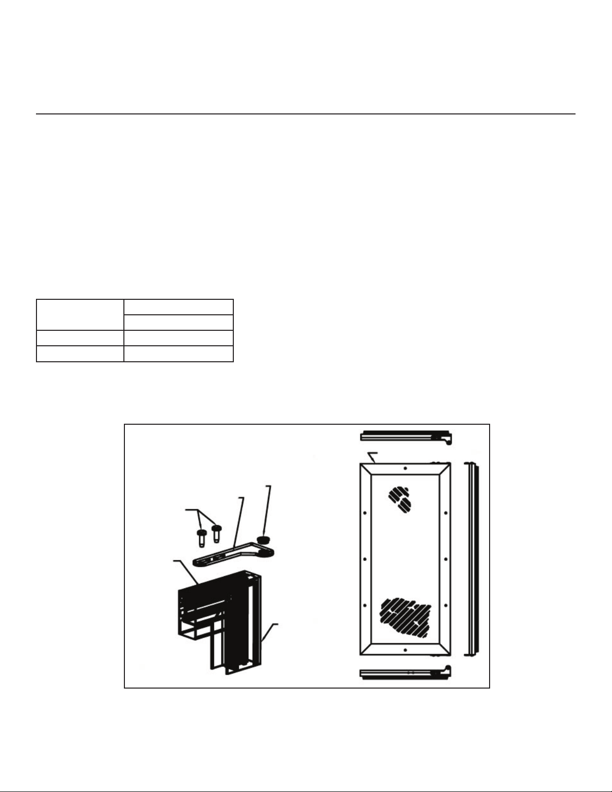
CUSTOM WOOD FRAME INSTALLATION INSTRUCTIONS
STEP 1: WOOD SCREWS REQUIRED
A #8 pan head wood screw should be used to properly 1.
secure the wood frame. A total of 10 screws will be
needed for a 3 1/2 inch toe kick or 8 screws for a 4
inch toe kick.
Use only pan head screws.2.
DO NOT select a screw that is longer than the wood 3.
thickness at the screw locations.
Use recommended pilot holes for the frame material 4.
(see Table A below).
Table A: Pilot Hole Drill Sizes For Wood Screw
Work Material
Wood Screw Size
8
Hardwood 3/32
Softwood 5/64
STEP 2: ASSEMBLING DOOR HINGE BRACKETS
Disregard if hinges are already attached.
Attach the top and bottom door hinge bushing brack-1.
ets to the door with the 1/4-20 machine screws and a
5/32 inch Allen head driver as shown in Figure 1.
Press in the shoulder bushings to the top and bottom 2.
door hinges. Make certain that the shoulder is to the
outside of the door as shown in Figure 1.
Test fit the door to the unit to make certain door will 3.
hang correctly. The door is hung correctly when the
top of the door is parallel to the top of the unit. Adjustments can be made by loosening the door hinge machine screws and moving the door hinge on the door.
Tighten all four machine screws after adjustments have 4.
been made.
Remove the door from the unit by removing the unit’s 5.
top hinge set screw and angling the door off of the
bottom hinge pin.
1/4-20 Machine
Screws
Door Hinge
Screw Holes
This surface parallel to the unit
(right hand swing door shown).
Shoulder Bushing
Door Hinge
Door Front
Surface
Figure 1: Typical Top and Bottom Door Hinge Assembly
1
Page 3
CUSTOM WOOD FRAME INSTALLATION INSTRUCTIONS
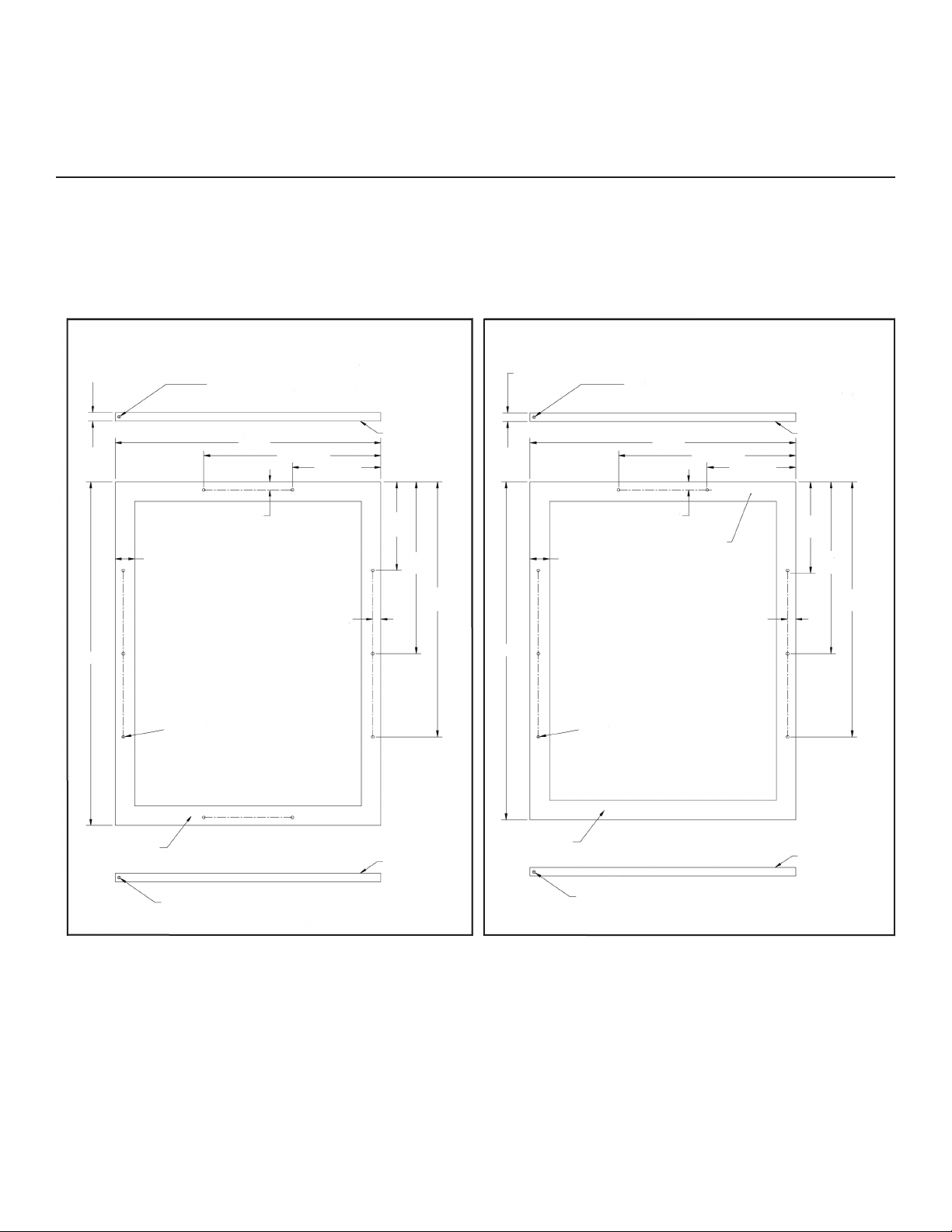
STEP 3: SELECTING AND PREPARING THE WOOD FRAME
For a 3.5 inch Toe Kick
(Covers the Entire Door Extrusion)
Optional for a 4 inch Toe Kick
(To Match Existing Cabinetry
Toe Kick Height)
30.31
0.63 Min
0.75 Max
0.25 x 0.375 Deep Hinge Screw Clearance Hole.
Locate and drill using door hinge hole after the door
has been aligned to the unit and when the wood is
positioned on door.
Mounting
23.44
7.81
1.72 Minimum
Width to Cover
Door Extrusion
0.72 0.72
Pre-Drilled
Pilot Holes
8 Places
Surface
(Non-Face) Side
7.81 7.81
22.50
29.81
0.63 Min
0.75 Max
0.25 x 0.375 Deep Hinge Screw Clearance Hole.
Locate and drill using door hinge hole after the door
has been aligned to the unit and when the wood is
positioned on door.
Mounting
Surface
(Non-Face) Side
15.1615.16
1.72 Minimum
Width to Cover
Door Extrusion
Pre-Drilled
Pilot Holes
8 Places
23.44
0.720.72
15.6315.63
7.81
Top
Surface
22.50
Mounting
Surface
(Non-Face) Side
Mounting
Surface
(Non-Face) Side
0.25 x 0.375 Deep Hinge Screw Clearance Hole.
Locate and drill using door hinge hole after the door
has been aligned to the unit and when the wood is
positioned on door.
Mounting
Surface
(Non-Face) Side
Mounting
Surface
(Non-Face) Side
0.25 x 0.375 Deep Hinge Screw Clearance Hole.
Locate and drill using door hinge hole after the door
has been aligned to the unit and when the wood is
positioned on door.
OPTIONAL LOCK AND KEY
The optional lock and key helps protect your contents from tampering or misuse. The lock and key kit contains a lock cylinder, catch bracket, keys, and an installation nut. Some assembly is required as the lock and key is installed on the front of
the wood frame. See Figures 2 and 3 above for lock and key installation dimensions.
2
Page 4
CUSTOM WOOD FRAME INSTALLATION INSTRUCTIONS
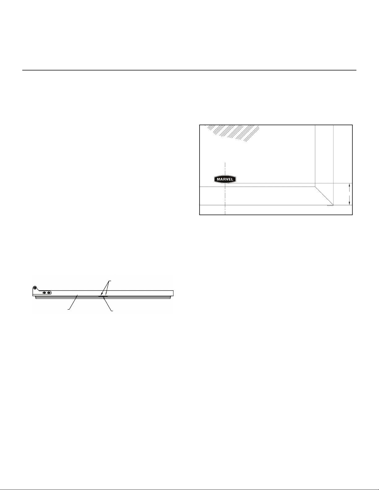
STEP 4: DETERMINING DOOR SWING
The door you received is for a right hand swing unit. If the
unit is to be changed to a left hand swing door, pre-drilled
striker plate holes are in place on the backside of the door
on both ends. No additional drilling is necessary to mount
the striker plate when you reverse the door swing. Just
unscrew the striker plate from the location it is mounted to
for right hand swing and then mount the striker plate at
the end opposite of its previous location with the existing
screws.
If your door has an inner door liner with formed in shelves,
it will need to be turned around for use in the left hand
swing. Using a small, flat blade screwdriver, pop the plastic screw covers up to access the Phillips screws that secure
the formed door liner to the door. Using a Phillips screwdriver, remove the Phillips screws that secure the formed
door liner to the door. Rotate the formed door liner 180
degrees, line up the mounting holes in the door liner with
the mounting holes on the door. Use the existing fasteners
and plastic screw caps to secure the formed door liner to
the door. Your door swing conversion is complete.
Remove the nameplate for the glass door by gently pulling
it up and away from the glass surface. Relocate the nameplate using the supplied nameplate locator (part number:
41006022).
2.38
Figure 5: Nameplate Locator
New Door Bottom
for Left Hand Swing
Door
Figure 4: Striker Plate Hole Location
Holes for screws to mount striker
plate are already pre-drilled at
factory.
Striker Plate for Plunger Light
Switch
3
Page 5
CUSTOM WOOD FRAME INSTALLATION INSTRUCTIONS
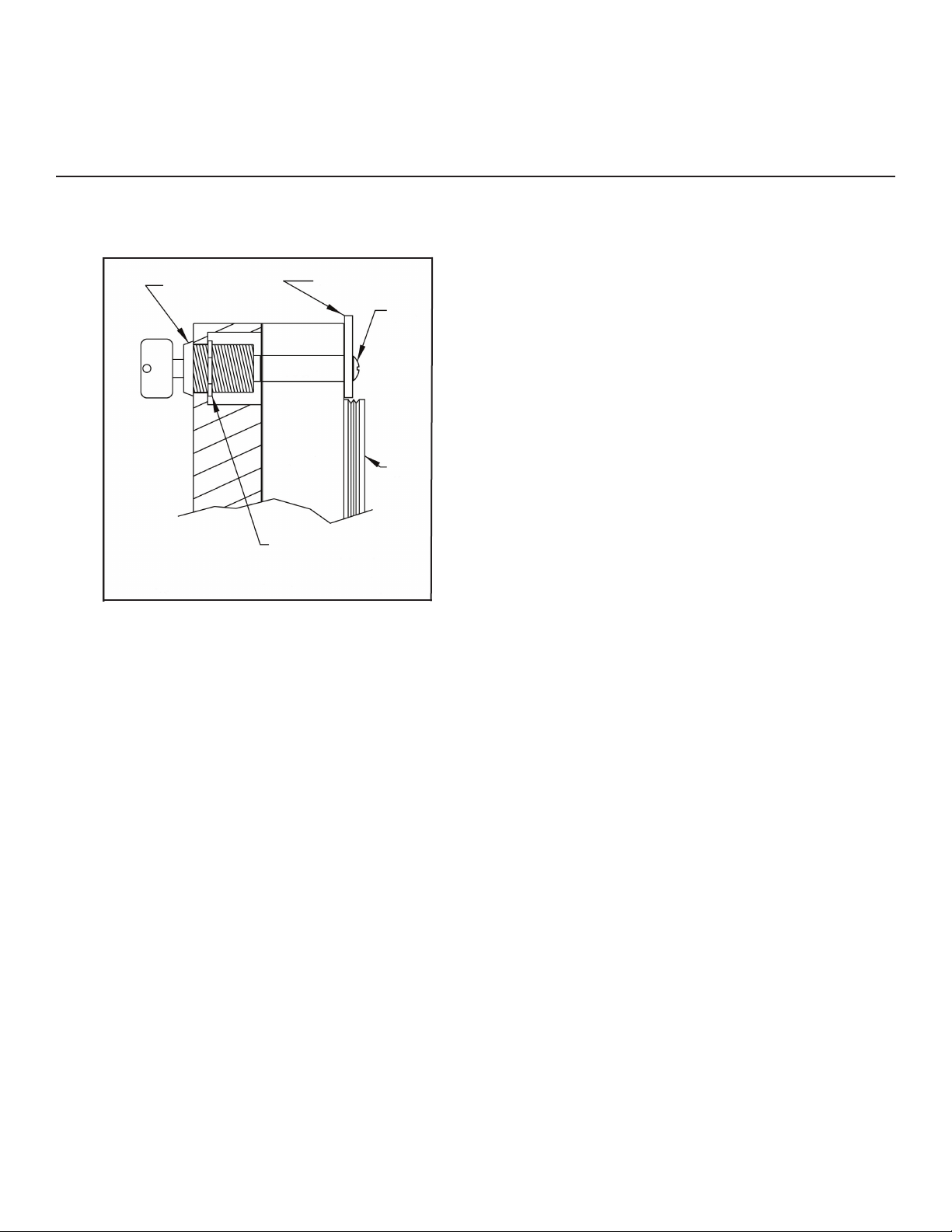
STEP 5: ATTACHING THE OVERLAY PANEL TO THE
DOOR (WITH THE LOCK AND KEY FEATURE)
Lock Body
Key
Lock Cam
Phillips
Lock
Extension
Door
Wood
Panel
Gasket
Lock Retainer Nut
Figure 6: Lock Installation Detail
NOTE: Two (2) brass lock extensions are
supplied with the Marvel Door Lock. The
longer one is for 3/4 inch thick panels,
and the shorter one is for 5/8 inch thick
panels.
Screw
Door
If the door is attached to the unit, remove it by un-1.
screwing the top Allen head set screw at the top hinge.
Remove the door by angling the door off of the bottom
hinge pin.
Install the supplied lock body into the wood panel. 2.
The lock and key assembly is supplied with your unit.
Secure the lock body by using the supplied 15mm
lock retaining nut and screwing it on the lock body’s
threaded section. Make sure that the lock’s set slot is
vertical, then tighten the 15mm nut with a 15mm deep
well socket.
Peel back door gasket to provide access to the screw 3.
holes used to mount the wood frame and the hole for
the lock’s extension section at the top of the door.
Set the wood frame flush to the front of the door in the 4.
desired location. Clamp wood frame to the door if
necessary. Check to see that the back of the lock in the
wood frame lines up with the hole in the door.
Insert the wood screws through the back of the door 5.
into the pilot holes in the wood frame and tighten.
Assemble the door lock’s Phillips screw, lock extension 6.
and lock cam and mount them to the back of the lock
body. The cam is to be oriented vertically, then tighten
the Phillips screw to secure the lock assembly.
Reinstall the door gasket by pressing into door chan-7.
nel. Make certain the corners are inserted fully. Insert
the key into the lock and make sure the lock operates
properly.
Install the door to the unit. Use the supplied plastic 8.
washers as shown in Figure 7.
Realigning the door may be necessary. Any final door 9.
adjustments can be made using a 1/8 inch Allen head
driver to adjust the door’s hinges (see Figure 7).
Attach the door light striker plate as shown using the 10.
5/16 inch Hex or Phillips head screws provided. Make
certain the light is able to turn on and off when the
door is opened and closed.
Attach the door to the unit by reversing steps number 1 11.
above.
Insert the key into the lock and verify that the lock cam 12.
works properly with the catch bracket on the cabinet
front.
4
Page 6
CUSTOM WOOD FRAME INSTALLATION INSTRUCTIONS
STEP 5: ATTACHING THE WOOD FRAME TO THE DOOR
(WITHOUT THE LOCK AND KEY FEATURE)
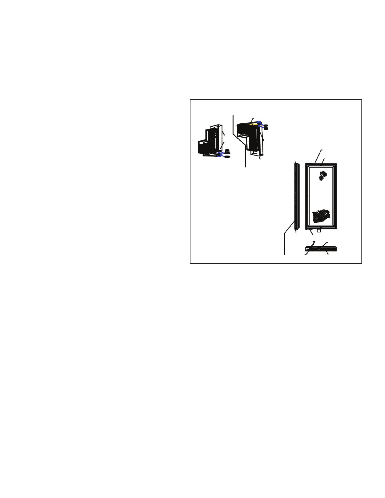
If the door is attached to the unit, remove it by un-1.
screwing the top Allen head set screw at the top hinge.
Remove the door by angling the door off of the bottom
hinge pin.
Peel back door gasket to expose the screw holes.2.
Set the wood frame flush to the front of the door in the 3.
desired location. Clamp wood frame to the door if
necessary.
Insert the wood screws through the back of the door 4.
into the pilot holes in the overlay panel and tighten.
Reinstall door gasket by pressing into door channel. 5.
Make certain the corners are inserted fully.
Install the door to the unit. Use the supplied plastic 6.
washers as shown in Figure 7.
Realigning the door may be necessary. Any final door 7.
adjustments can be made using a 5/32 inch Allen
head driver to adjust the door’s hinges (see Figure 7).
Attach the door light striker plate as shown using the 8.
Hex or Phillips head screws provided. Make certain the
light is able to turn on and off when the door is opened
and closed.
Attach the door to the unit by reversing step number 1 9.
above.
CAUTION
Door can become
disengaged if washers
are not installed.
CAUTION
Door may not swing
properly- if all nylon
components are not
installed as shown.
Bottom Hinge Corner
disengaged if washers
Wood
Frame
Door Hinge
.75 OD x
.443 ID
Washer
.75 OD x
.257 ID Washer
3 Nylon Hardware
Components at
Bottom Hinge
Figure 7: Hinge Hardware Installation Details
CAUTION
Door can become
are not installed.
Cabinet Hinge
Top Hinge Corner
2 Nylon Hardware
Components at
Bottom Hinge
0.625 OD x 0.218 ID Washer
Shoulder Bushing
Door Hinge
Wood Frame
Door Hinge
Adjustment Screws
Attached
Wood Frame
Magnetic Door Gasket
0.38 Clearance Holes
for Frame Wood Screws
8 Holes
5/32 inch Allen Head Screws
for Hinge Adjustment
Light Door Striker Plate
Bottom of Door
5
Page 7

NOTES
6
Page 8

Marvel Industries
P.O. Box 997
Richmond, IN
47375-0997
800.428.6644
An AGA Company
www.lifeluxurymarvel.com
41006981 Rev F
10.30.07
All specifications and product designs subject to change without notice. Such revisions do not entitle
the buyer to corresponding changes, improvements, additions, replacements or compensation for
previously purchased products.
 Loading...