

Page 1

Installation
Operation
and
Maintenance
Instructions
Combo Ice Machine
6CiM
6OCiM
MARVEL
Page 2
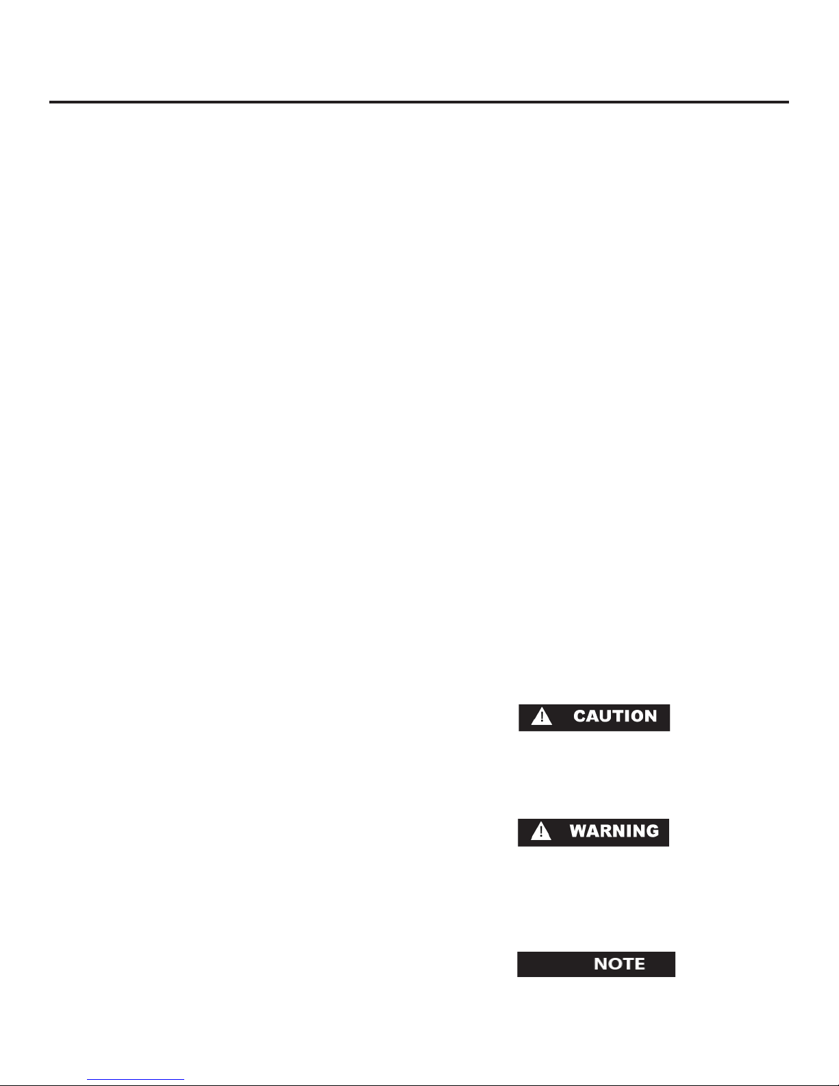
TABLE OF CONTENTS
Unpacking your refrigerator........................
Removing the packaging......................
Warranty Registration.....................
Installing your refrigerator......................................3
Selecting the location..........................
Cabinet Clearances..................................
Outdoor Installation.........................
Leveling legs......................................
Grounding method..............................
Electrical Requirements........................
Connecting the water supply...............
Using Your Refrigerator..................................
Setting the temperature control..............
Defrosting instructions........
Dimensions For 6CiM and 6OCiM Solid Door........ 6
Recommended Rough in Opening Dimensions
For 6CiM and 6OCiM Solid Door........................ 6
Dimensions For 6CiM Solid Overlay Door.............
Recommended Rough in Opening Dimensions
For 6CiM Solid Overlay Door.
Full Overlay Panel Installation Instructions.
Care and Cleaning...................................
Condenser air flow.............................................10
Cabinet..................................
Interior...............................................................10
Replacing light bulb............................................10
Troubleshooting Guide....................
Diagnostic LED......................................................13
Obtaining Service.........................
Household Product Warranty................
....
.............
...............
.......................
....................
......................
.........
............
.................
.............
.........
................
.............
...
...........
...........
..................
.......
...........
..............
..............
............
..........
...............
..2
..2
....2
..3
.3
...3
...3
.3
....3
..4
.5
...5
..5
7
.7
.8
..10
.....10
...11
..13
...14
Important Safety Instructions
Warnings and safety instructions appearing in this
guide are not meant to cover all possible conditions and situations that may occur. Common sense,
caution, and care must be exercised when installing,
maintaining, or operating this appliance.
Recognize Safety Symbols,
Words, and Labels.
1
CAUTION-Hazards or unsafe practices which could
result in personal injury or property or product damage.
WARNING-Hazards or unsafe practices which could
result in personal injury.
NOTE-Important information to make a problem free
installation.
Page 3
UNPACKING YOUR REFRIGERATOR
Remove Packaging
Your refrigerator has been packed for shipment with
all parts that could be damaged by movement securely
fastened. Cut the banding material at the bottom of the
carton, unfold the carton at the bottom and remove the
carton from the appliance. Remove the plastic bag, styrofoam corner posts and any tape holding the door closed
and internal components in place. The owners manual is
shipped inside the refrigerator in a plastic bag along with
the warranty registration card.
Important
Keep your carton packaging until your refrigerator has
been thoroughly inspected and found to be in good condition. If there is damage, the packaging will be needed
as proof of damage in transit. Afterwards please dispose
of all items responsibly in particular the plastic bags
which can be a suffocation hazard.
Warranty Registration
It is important you send in your warranty registration card immediately after taking delivery of your refrigerator or you can
register online at www.marvelrefrigeration.com.
The following information will be required when registering
your unit.
Model Number
Serial Number
Date of Purchase
Dealers name and address
The model number and serial number can be found on the
serial plate which is located inside the cabinet on the left side
near the top.
Note to Customer
This merchandise was carefully packed and thoroughly
inspected before leaving our plant. Responsibility for
its safe delivery was assumed by the retailer upon acceptance of the shipment. Claims for loss or damage
sustained in transit must be made to the retailer.
DO NOT RETURN DAMAGED MERCHANDISE TO THE
MANUFACTURER - FILE THE CLAIM WITH THE RETAILER.
If the unit was shipped or has been laying on its back for
any period of time allow the refrigerator to sit upright for
a period of at least 24 hours before plugging in. This will
assure oil returns to the compressor. Plugging the refrigerator in immediately may cause damage to internal
parts.
Help Prevent Tragedies
Child entrapment and suffocation are not problems of the
past. Junked or abandoned refrigerators are still dangerous - even if they sit out for “just a few days”.
If you are getting rid of your old refrigerator, please follow
the instructions below to help prevent accidents.
Before you throw away your old refrigerator or freezer:
Take off the doors or remove the drawers.•
Leave the shelves in place so children may not easily •
climb inside.
2
Page 4
INSTALLING YOUR REFRIGERATOR
Select Location
The proper location will ensure peak performance of your
appliance. We recommend a location where the unit will
be out of direct sunlight and away from heat sources. To
assure your product performs to specifications the recommended installation location temperature range is from 65
to 90°F (18 to 32°C).
Cabinet Clearance
Ventilation is required from the bottom front section of the
unit. Keep this area open and clear of any obstructions.
Adjacent cabinets and counter top can be installed around
the unit as long as the grille and door access remain unobstructed.
Outdoor Installation
Only the 6OCiM model is suitable for outdoor installations.
A ground fault circuit interrupter electrical receptacle is to
be used to supply electrical power to the refrigerator for
outdoor applications. Contact an electrician if you need
to install one to supply electrical power to your outdoor
refrigerator. Do not install in an environment where the unit
will be exposed to direct sun exposure as this may result in
unsatisfactory performance.
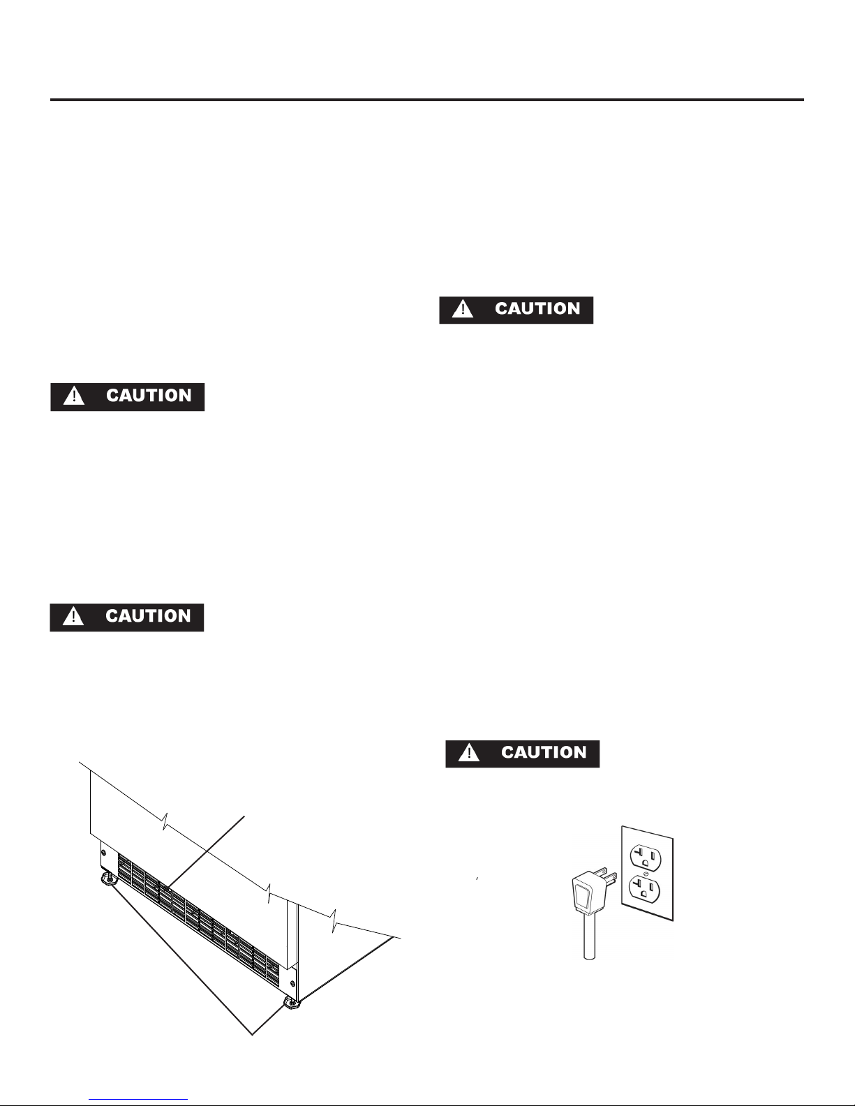
Front Grille
Do not obstruct the front grille. The openings within the
front grille provides air to flow into and exit from the refrigerator condenser. For this reason it is important this area to
not be obstructed and be kept clean. Marvel does not recommend the use of custom made grilles as air flow may be
restricted because of inadequate openings. (See Figure 1).
Leveling Legs
Adjustable legs at the front and rear corners of the unit
should be set so the unit is firmly positioned on the floor
and level from side to side and front to back. Turn leveling
legs clockwise to raise unit, counterclockwise to lower it.
(See Figure 1).
Do not splash or spray water from a hose on the re-•
frigerator! Doing so may cause an electrical shock,
which may result in severe injury or death.
This unit should not, under any circumstances, be •
ungrounded.
Grounding Method
This product is factory equipped with a power supply cord
that has a three-pronged, grounded plug. It must be
plugged into a mating grounding type receptacle in accordance with the National Electrical Code and applicable local codes and ordinances (see Figure 2). If the circuit does
not have a grounding type receptacle, it is the responsibility
and obligation of the customer to exchange the existing
receptacle in accordance with the National Electrical Code
and applicable local codes and ordinances. The third
ground prong should not, under any circumstances, be cut
or removed.
Electrical Connection
115 volts, 3.3 amps running max. 15 amp dedicated circuit
required. 3 prong grounded receptacle required.
Do not use an extension cord
with this appliance.
Front Grille,
keep this
area open.
Figure 1
Leveling Legs
3
Figure 2
Page 5
Water Supply
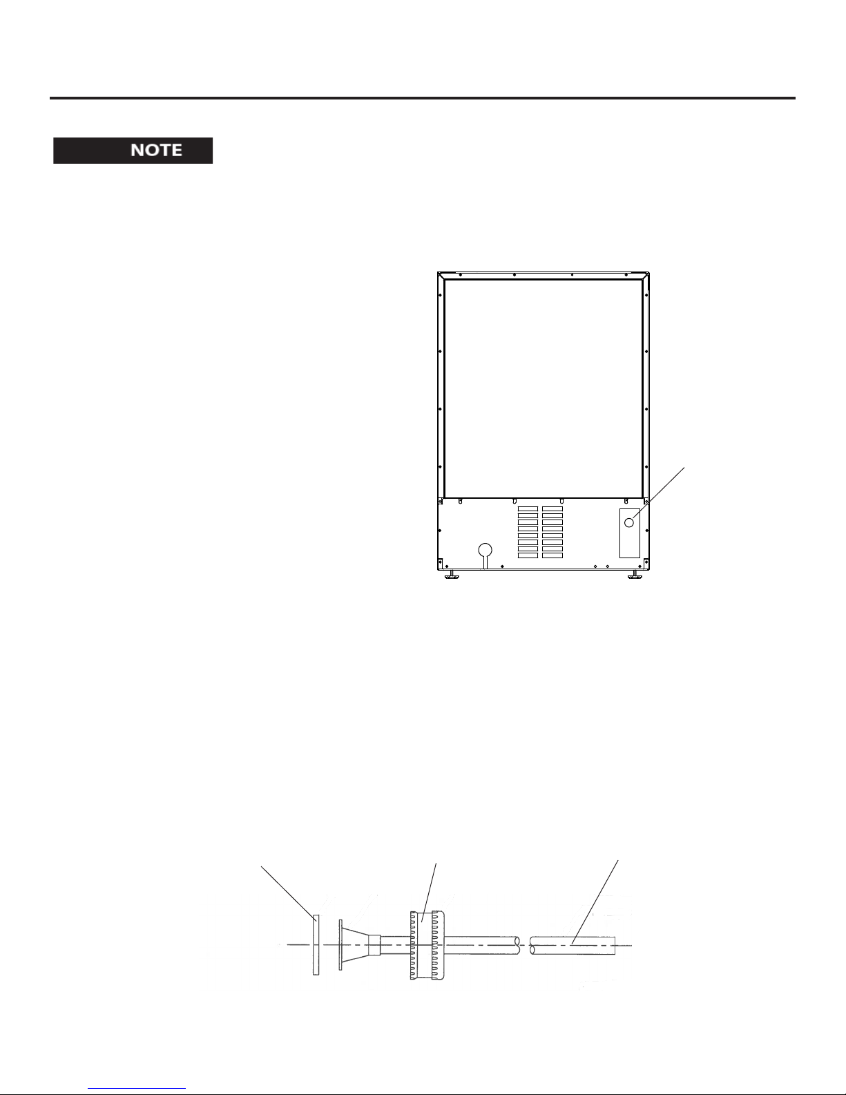
Observe and follow all local building codes when installing this appliance.
Attach the supplied water line adapter (Figure 4) to the
water valve inlet on the back of the refrigerator (See
Figure 3). Be sure the rubber washer is in place in the
inlet valve nut. Bend the 1/4” copper tubing to suit your
installation being sure not to kink the tubing. Use 1/4”
copper tubing for your water supply which is available at
any local hardware or plumbing supply store. Connect
the copper tubing water supply to the copper tubing from
the adapter assembly with the provided brass union.
Water pressure must be at a minimum of 20 psi for
proper operation.
Make certain all water connections are watertight after
installation. Form the tubing so that it will not vibrate
against the cabinet body or kink when your refrigerator is
set in position.
INSTALLING THE WATER SUPPLY
Water supply
inlet
Rubber washer
Back view of
Inlet valve nut
Figure 3
refrigerator
1/4” copper tubing
Figure 4
4
Page 6
USING YOUR REFRIGERATOR
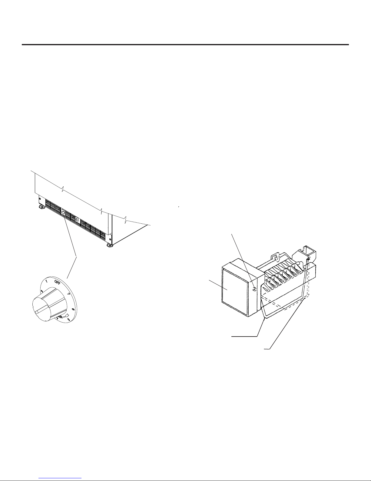
Setting the temperature control:
Initially set the cold control midway between the numbers
(between the #3 and #4).After at least 2 hours adjust to
the temperature that suits you. The higher the number you
select, the cooler the temperature. (See figure 5). After
loading the refrigerator allow at least 24 hours for your
refrigerator to reach a new temperature setting.
The refrigerator section temperature of the unit can be adjusted using the adjusting slide located in the left side and
rear of the refrigeration section. Turn in the cold direction
indicated to make the refrigeration section colder and the
opposite direction to warm the refrigeration section.
Figure 5
A drip tray heater is located in the unit for proper removal of
condensation. The heater will remain on as long as the unit
is plugged in. The control knob will not turn the heater off.
Unplug or disconnect power to the unit if you are planning to
leave the unit off or unattended for extended periods of time.
Icemaker operation
Make certain water pressure is at least 20 psi and no •
more than 120 psi and the water is turned on.
The unit must be installed level for proper icemaker •
operation.
The shutoff arm wire must be down in its lowest position •
for the icemaker to operate.
Make sure there are no obstructions in the fan inlet and •
outlet. The fan is located beside the icemaker at the top
of the freezer section.
When the freezer section and icemaker unit has suf-•
ficiently cooled, the icemaker will harvest ice cubes
automatically.
When the ice bucket is full, the ice maker will automati-•
cally shut off.
You may manually stop the icemaker by raising the shut •
off arm to the locking position at the up most position.
Water adjustment screw behind cover
on side of housing
Cold control
underneath door
in grille
Defrosting
This unit uses an electronic control system to control both
defrost and refrigeration functions. This feature eliminates
the inconvenience of manual defrosting of the evaporator
in normal conditions. If commodities or ice accidently clogs
the drip tray, the obstruction must be removed for proper
defrost performance. It is normal for some water droplets
to be left on the evaporator or drip tray. These will refreeze
and be removed in the next defrost cycle.
Defrosting is factory set to run after the compressor has
run approximately 12 hours. For climates with high humidity levels and / or repeated door openings, an optional 6
hour compressor run time is already programmed into the
control. A switch will have to be set at the control for this
change to take place (consult your distributor or authorized
service center).
Cover
pulls off
Figure 6
Arm down, icemaker
will operate
Arm up, stops operation
When operation of the appliance is to be discontinued
for any length of time, the ice cube cavity in the icemaker
should be emptied and dried. The water supply and power
supply should also be shut off and the ice bucket should be
emptied and cleaned.
If the ice is not used regularly, it will clump together with
time. For best ice results, discard ice in the bin as required
and allow the icemaker to make a new fresh batch of ice.
5
Page 7
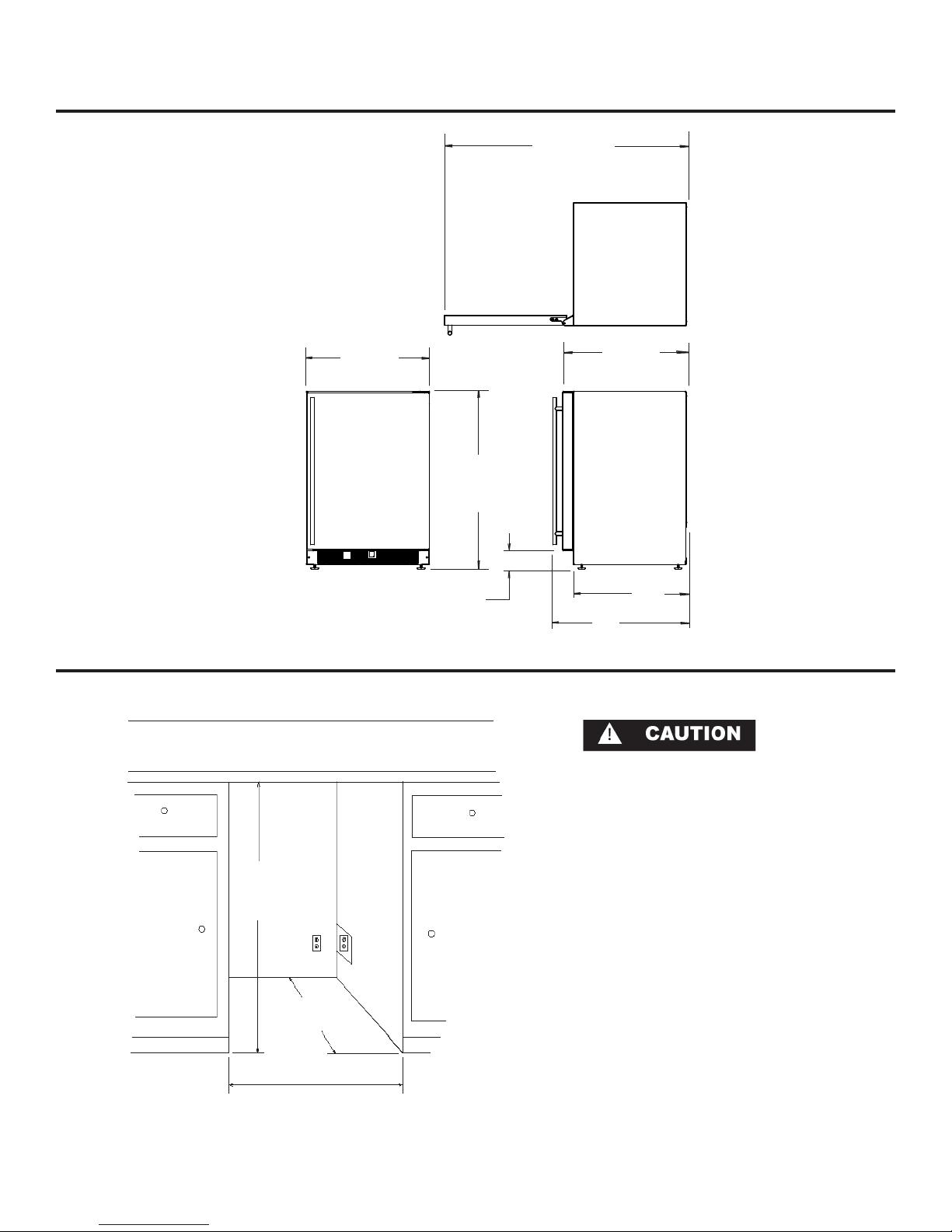
DIMENSIONS FOR MODELS 6CiM & 6OCiM SOLID DOOR
47”
(119.38cm)
23-7/8”
(60.66cm)
34-1/4” to 34-1/2”
87 to 87.6cm)
3” to 3-1/4”
7.62 to 8.26cm)
24-1/16”
(61.11cm)
26”
(66.04cm)
22”
(55.8cm)
Recommended Rough in Opening Dimensions, 6CiM & 6OCiM Solid Door
Electrical Requirements: 115 volts,
3.3 amps running max. 15 amp
dedicated circuit required. 3 prong
grounded receptacle required.
34-1/2”
(87.6 cm)
*24” (61 cm)
standard cabinet
depth
24” (61 cm)
Power outlet can be located in the
back wall behind unit. Add 1” to
depth for thickness of plug, or recess
outlet 1” into the wall. Power outlet
can also be installed in adjacent
cabinetry with a cutout for routing of
power cord. Follow all local building
codes when installing electrical and
unit.
Product weight = 120 lbs. (54.5 kg.)
* Depth dimension may vary depending on
each individual installation.
6
Page 8
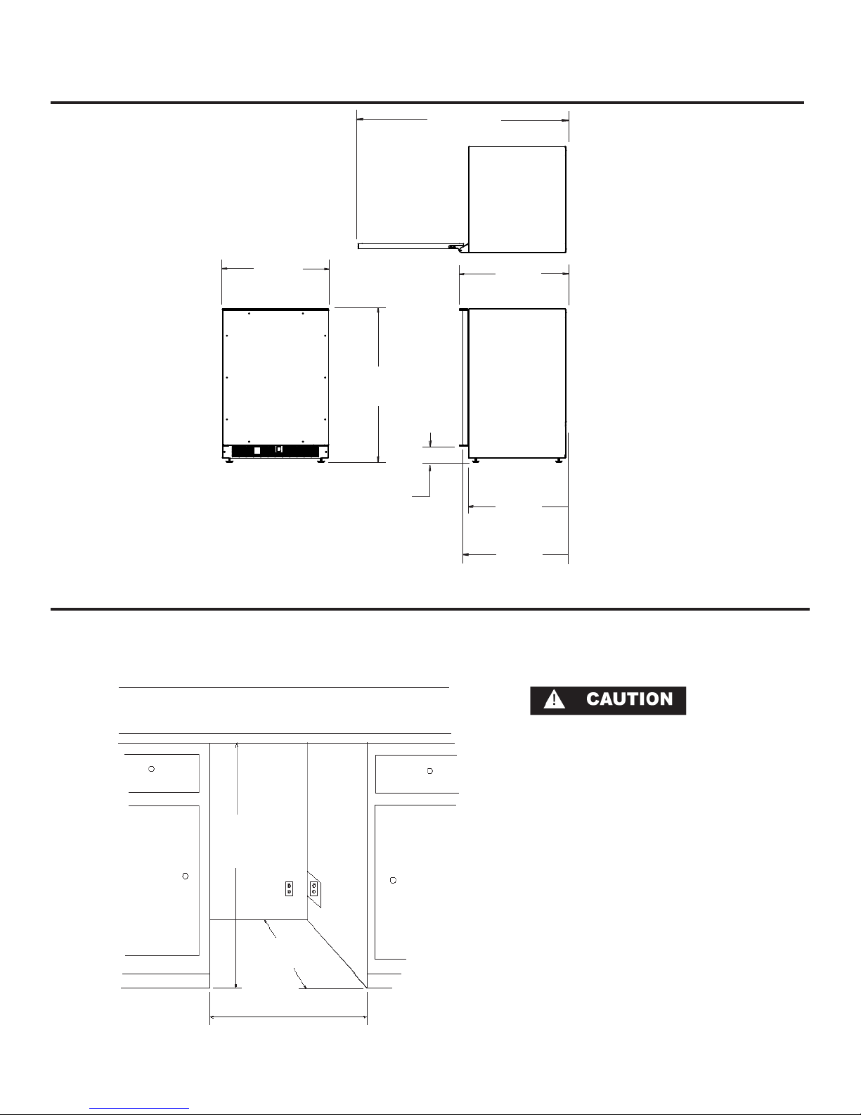
DIMENSIONS FOR MODEL 6CiM SOLID OVERLAY DOOR
46-27/32”
(119.02cm)
23-7/8”
(60.66cm)
34-1/4” to 34-1/2”
87 to 87.6cm)
3” to 3-1/4”
7.62 to 8.26cm)
24-1/16”
(61.11cm)
22”
(55.8cm)
23-5/16”
(59.21cm)
Recommended Rough in Opening Dimensions, 6CiM Solid Overlay Door
34-1/2”
(87.6 cm)
*24” (61 cm)
standard cabinet
depth
24” (61 cm)
7
Electrical Requirements: 115 volts,
3.3 amps running max. 15 amp
dedicated circuit required. 3 prong
grounded receptacle required.
Power outlet can be located in the
back wall behind unit. Add 1” to
depth for thickness of plug, or recess
outlet 1” into the wall. Power outlet
can also be installed in adjacent
cabinetry with a cutout for routing of
power cord. Follow all local building
codes when installing electrical and
unit.
Product weight = 120 lbs. (54.5 kg.)
* Depth dimension may vary depending on
each individual installation.
Page 9
FULL OVERLAY PANEL INSTALLATION INSTRUCTIONS
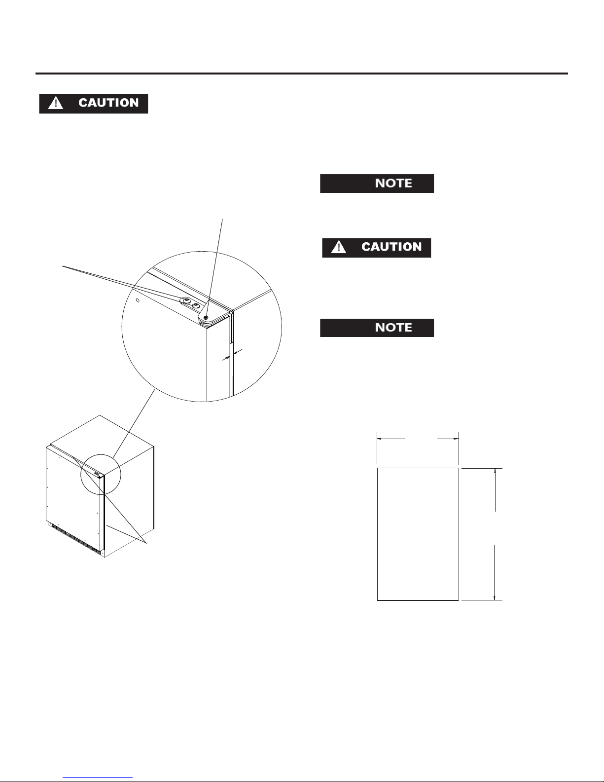
For the door closer to work properly it is necessary to
maintain a minimum space of 9/32” (7mm) between the
door and cabinet flange as shown . This space can be
adjusted by adjusting the top and bottom hinge adapters.
Step 1: Verify door alignment
The door should be parallel to the sides and top of the
refrigerator. If alignment is necessary the door may be
adjusted by loosening the 2 screws which secure the
hinge adapter brackets to the door and adjusting the
door side to side. Use a 5/32” allen wrench for this procedure. (See Figure 7 below).
Top hinge pin
Hinge adapter screws loosen these to adjust door, on
remove to remove
the door.
the top and bottom of the
door
9/32”
(7mm)
Step 4: Cut overlay panel
Depending on the refrigerator model cut the overlay
panel to the dimensions shown in Figure 8.
For overlay with lock option panel thickness to be
3/4” (19mm) maximum to 5/8” (16mm) minimum.
Weight of the overlay panel should not exceed 20 pounds
(9.1 kilograms).
Door must be
parallel to top
Figure 7
and sides of
refrigerator
Step 2: Remove door
Remove the top hinge pin from the hinge with an 1/8”
allen wrench. Remove the door by angling the top of the
door outward and lifting the door off the bottom hinge.
(See detail in Figure 7).
Step 3: Remove gasket
Lay the door on its front being careful not to scratch it.
Remove the door gasket by peeling up and out of the
channel.
23-5/8”
(59.99cm)
Front of
overlay
panel
30-5/16”
(76.99cm)
Figure 8
Step 5: Clamp panel to door
Set the overlay panel on the door front, align the edges,
and clamp together. Clamp the panel firmly but be careful not to crush the foam in the door or scratch the door.
8
Page 10
FULL OVERLAY PANEL INSTALLATION INSTRUCTIONS
SECTION A-A
SCALE 1 : 1
LOCK
NUT
BRASS EXTENSION
CAM
PHILLIPS SCREW
13/16 COUNTER
BORE 7/16 DEEP
15/32 HOLE
3/4 INCH
WOOD PANEL
SPRING WASHER
INNER
DOOR
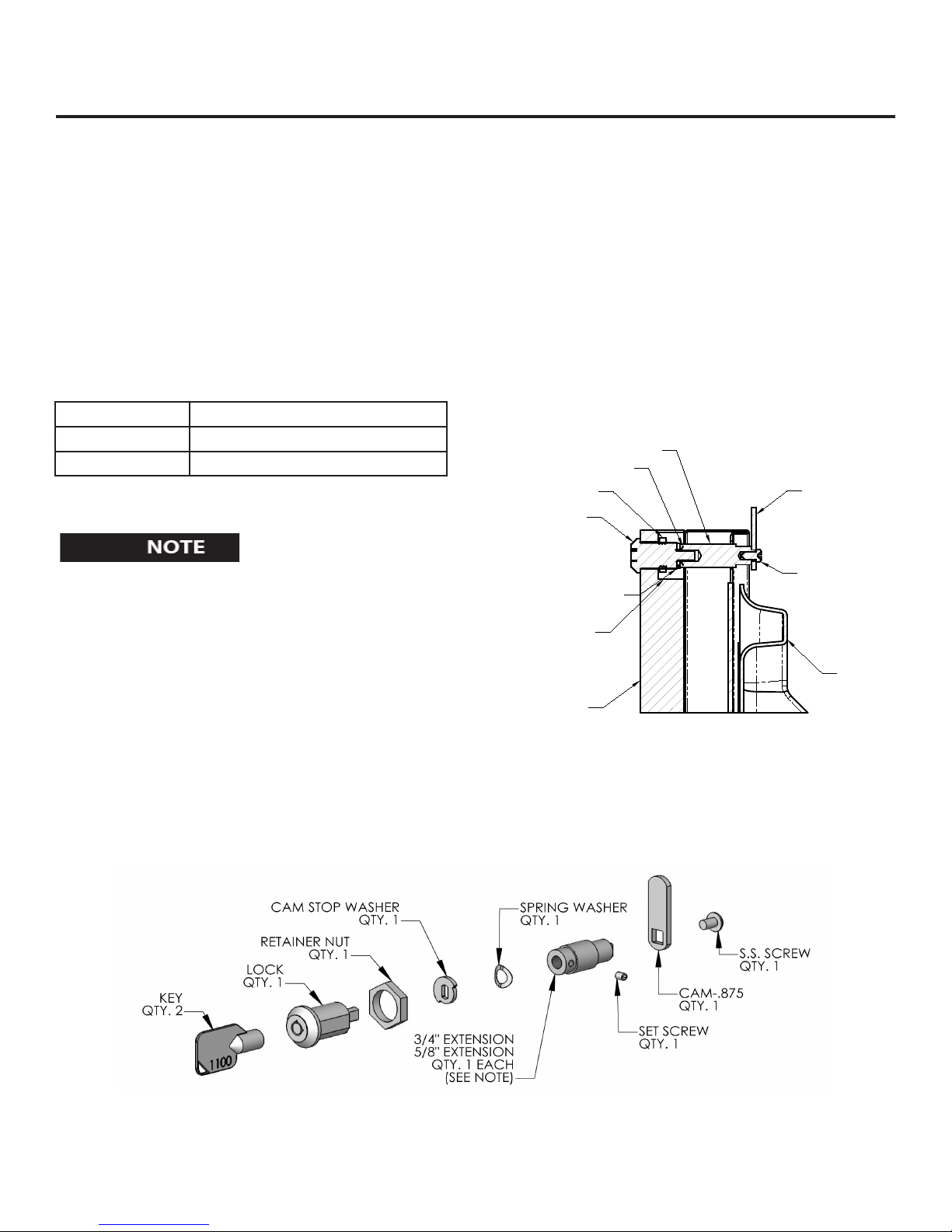
Step 6: Drill holes in overlay panel
Remove the hinge adapter bushings from the top and
bottom door hinge adapters. (See Figure 9).Using the
holes in the hinge adapters drill 5/16” (8mm) diameter
clearance holes into the overlay panels 3/4” (20mm)
deep. These will be clearance holes for the top and bottom hinge pins.
Also at this time drill the screw pilot holes (10 required)
for attaching the overlay panel to the door. Select the size
of the hole from Table A. Be careful not to drill the pilot
holes through the overlay panel but only 1/2” (12.7)mm
deep.
Material Type #8 Wood Screw
Hardwood 3/32” (2.4mm) Diameter. Pilot Hole
Softwood 5/64 (2.0mm) Diameter. Pilot Hole
Table A
If your refrigerator has a door lock proceed to Step 7.
If your refrigerator does not have a door lock proceed
to Step 9.
Step 8: Assemble the lock parts
Two (2) lock extensions are supplied with the lock. Use
the longer extension for a 3/4” thick overlay panel and
the shorter one for a 5/8” thick panel. Assemble the lock
extension, cam stop washer, spring washer, and set screw
to the lock as shown in Figure 9 and 10.
Install this assembly into the overlay panel and secure
with the retaining nut using a 15mm socket. Make sure
the key slot in the lock is vertical.
Step 7: Mark and drill lock hole.
Locate and mark with a pencil the location of the lock
hole on the overlay panel, this is the hole in the top corner of the handle side of the door. Remove the clamp and
remove the overlay panel from the door. On the backside
of the panel where you marked the lock location drill a
13/16” (20.5mm) diameter counterbore 7/16” (11.0mm)
deep into the overlay panel. Drill a 15/32” (12.0mm)
diameter hole through the overlay panel centered on the
counterbore being careful not to splinter the wood on the
face side of the panel. (See Figure 9).
Figure 9
9
Figure 10
Page 11
CARE AND CLEANING
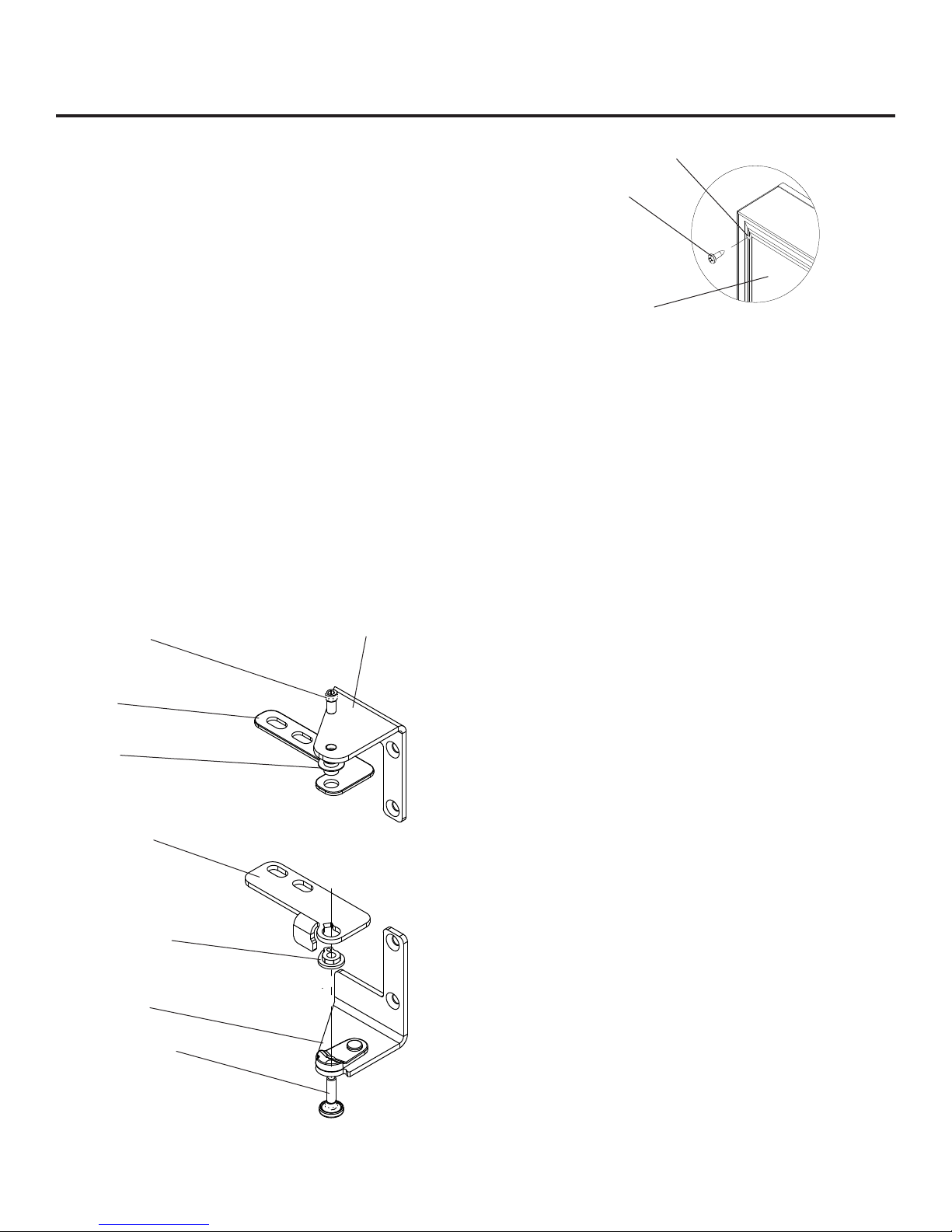
Step 9: Secure overlay panel to the door.
With the #8 wood screws provided fasten the overlay
panel to the door. (See Figure 12).
Step 10: Install lock cam (Models with locks only).
Attach the lock cam to the back of the lock assembly with
the phillips head machine screw provided. Orient the lock
cam vertically when installing on the lock.
Step 11: Install door gasket
Press the door gasket into the door channel. Make
certain the gasket corners are fully inserted. If applicable
insert the key into the lock and make certain the lock
operates properly.
Step 12: Install the door
Install the top and bottom hinge adapter bushings back
into the hinge adapters that were removed in step 6.
Install the door by reversing the procedure from step 2.
Install the top hinge pin so the screw head is flush with
the top surface of the hinge. If applicable insert key into
lock and verify the lock cam works properly with the
catch bracket on the front of the refrigerator cabinet.
Clearance hole through
door gasket channel
#8 Wood Screw
Back of door
Figure 12
Condenser Air Flow
The machine compartment located beneath the cabinet
does not require frequent cleaning; however, satisfactory
performance depends on adequate ventilation. Be sure
nothing obstructs the required air flow openings in front of
the cabinet. At least once or twice a year, brush or vacuum
lint and dirt from the front grille openings. See Figure 1 on
page 3.
Cabinet
The painted cabinet can be washed with either a mild soap
and water and thoroughly rinsed with clear water. NEVER
use abrasive scouring cleaners.
Top hinge pin
Top door hinge
adapter
Top hinge adapter
bushing
Bottom door
hinge adapter
Bottom hinge
adapter bushing
Bottom hinge
with cam
Bottom hinge pin
Top hinge
Interior
Wash interior compartment with mild soap and water. Do
NOT use an abrasive cleaner, solvent, polish cleaner or
undiluted detergent.
Care of Unit
Avoid leaning on the door, you may bend the door 1.
hinges or tip the unit.
Exercise caution when sweeping, vacuuming or mop-2.
ping near the front of the unit. Damage to the grille
can occur.
Periodically clean the interior of the unit as needed.3.
Periodically check and/or clean the front grille as 4.
needed.
Replacing the light bulb.
Unplug the power cord from the wall receptacle.1.
Open the cabinet door.2.
Remove the 3 screws on the front face of the light lens.3.
Remove the lens.4.
Unscrew the existing bulb and replace with an equiva-5.
lent 15 watt, intermediate base appliance bulb. Do not
replace with a bulb higher than 15 watts.
Reassemble parts and plug in power cord.6.
Figure 11
Right hand
hinges shown
To clean the light assembly, disconnect the power cord and
wipe the assembly with a mildly damp cloth. Dry the unit
completely before connecting the power cord.
10
Page 12
TROUBLESHOOTING YOUR REFRIGERATOR
Before You Call for Service
If the unit appears to be malfunctioning, read through this
manual first. If the problem persists, check the troubleshooting guide below. Locate the problem in the guide and refer
to the cause and its remedy before calling for service. The
problem may be something very simple that can be solved
without a service call. Some remedies listed in the Troubleshooting Guide are very complex. Consulting or contracting
a qualified service technician may be necessary.
Electrocution Hazard - Never attempt to repair or perform maintenance on the unit until the main electrical power has
been disconnected.
Problem Possible Cause Remedy
Unit operates but does not produce any
ice
Small ice cubes Water input may require adjust-•
Ice cubes are sticking together. Ice consumption is low.•
11
The unit has just been started and •
it has been less than 24 hours.
Water supply is not turned on.•
Inadequate water pressure to unit.•
The icemaker shut off arm is in the •
uppermost position.
Freezer section has not reached •
temperature.
Thermostat control knob set too •
warm.
Blower inlet and /or outlet is re-•
stricted.
Condenser fan air flow is restrict-•
ed.
Room and/or water temperature is •
too warm.
ment.
Room temperature is too warm.•
Typical ice production is 2 pounds •
per day. Allow for the freezer section to reach temperature and the
icemaker to cycle and accumulate
ice.
Turn on water supply to the unit.•
Water pressure to the unit must be •
at a minimum of 20 psi.
When the icemaker shut off arm is •
in the uppermost position, the icemaker is off. Flip the shut off arm
down to turn on the icemaker.
Allow the freezer section to reach •
temperature.
Turn the temperature control knob •
to a higher number to allow the
unit to run colder. Allow 24 hours
before readjusting the temperature
control.
Keep blower area clear from com-•
modities for proper operation.
Make certain the grille in front of •
the unit is free and open for air circulation. Clean grille as required.
Move the unit to an area where •
ambient temperature is below
90°F. The unit should not be
placed next to a heat source such
as an oven. Check for cold water
connection.
Due to differing water pressures, •
the icemaker water input may require adjustment. See Figure 6 on
page 5 for water adjustment screw
location.
Use the ice in the bin frequently. •
Ice will stick together if left in insulated bin over long periods of time.
Move the unit to an area that is •
below 90°F.
Page 13
TROUBLESHOOTING YOUR REFRIGERATOR
Problem Possible Cause Remedy
Unit too warm or too cold inside. Control set too warm or cold•
Temperature control slide in the •
refrigerator section too far open or
closed.
Airflow to front grille blocked.•
Excessive usage or prolonged door •
openings.
Door gasket not sealing properly.•
No interior light in compartments. Light bulb burned out.• Replace light bulb.•
Adjust temperature colder or •
warmer as required. Allow 24
hours for temperature to stabilize.
Adjust temperature control slide as •
necessary in the refrigerator section of the unit.
Airflow must not be obstructed to •
front grille. See “clearances” on
page 3.
Allow temperature to stabilize for •
at least 24 hours.
Adjust or replace door gasket.•
Light will not go out when door is
closed
Noise or Vibration Unit not level•
Unit will not run. Unit turned off•
Moisture collects on outside surface of
cabinet.
Moisture collects on inside of the unit. To many door openings.•
The unit is warm inside with the temperature control knob in the “OFF”
position.
Items on door shelf sometimes freeze. The upper 2 shelves can freeze •
Door not activating light switch.• Verify cabinet is level, refer to page •
Water line tubing vibration.•
Power cord not plugged in.•
No power at outlet.•
Hot and humid conditions.• Extremely hot and humid condi-•
Prolonged door openings.•
Hot and humid conditions•
Defrost thermistor out of specifica-•
tion.
Drip tray heater is on.• The drip tray heater will stay ener-•
under warm conditions.
3 for leveling instructions.
Verify the door is aligned properly, •
refer to page 8 for instructions.
Level unit, see “Leveling Legs” on •
page 3.
Adjust the tubing as necessary to •
eliminate unwanted vibrations.
Turn unit on. See “Set the tempera-•
ture control” on page 4.
Plug in power cord.•
Check house circuit.•
tions can cause condensation on
outside of the cabinet. As humidity
and/or temperature decreases, the
condensation will disappear.
Limit the amount of door open-•
ings.
Limit the amount of time with the •
door open.
Extreme hot and humid conditions. •
Move unit to a controlled environment. May consider having the
defrost setting changed from 12
hours to 6 hours.
Consult dealer or servicer for •
diagnosis.
gized in the off position. Unplug
the unit if storing or leaving the
unit off for an extended period.
Turn the temperature control knob •
to a lower number or move the
commodities to the refrigerated
section.
12
Page 14
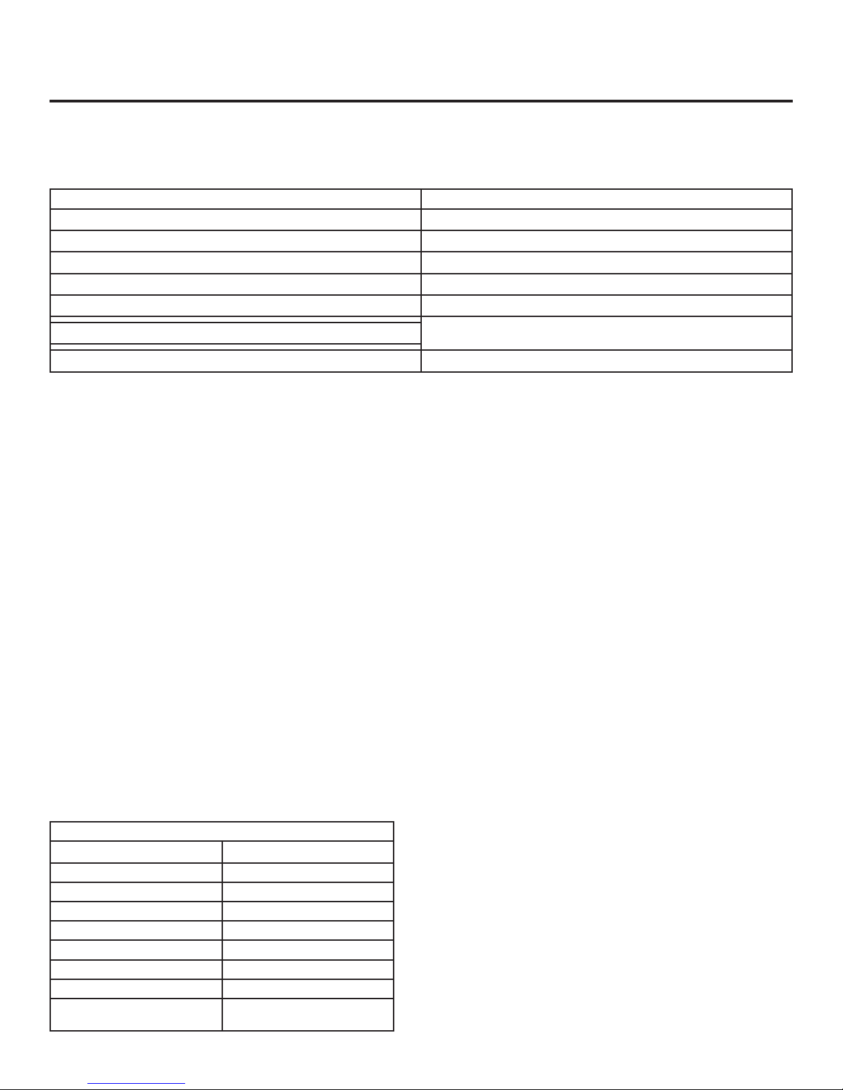
DIAGNOSTIC LED AND OBTAINING SERVICE
Diagnostic LED
In the back of the unit behind the grille there is a diagnostic/status LED. This LED is used to help diagnose any
problems with the unit and to tell its status.
LED Status Code/Problem
Not on or blinking Unit does not have power.
Steadily blinking once per second Unit temperature control is in the “OFF” position.
Continuously on Unit is “ON” and operating properly.
2 blinks and pause; repeated pattern Defrost thermistor out of range.
3 blinks and pause; repeated pattern Evaporator normal cycling thermistor out of range.
4 blinks and pause; repeated pattern
2 blinks, pause, 3 blinks, pause; repeated pattern. Both defrost and evaporator thermistors are out of range.
Control potentiometer out of range.
If Service is Required:
If the product is within the first year warranty •
period please call Marvel Customer Service at
800.223.3900 for directions on how to obtain warranty coverage in your area.
If the product is outside the first year warranty period, •
Marvel Customer Service can provide recommendations of service centers in your area. A listing of
authorized service centers is also available at www.
marvelrefrigeration.com under the service and support section.
In all correspondence regarding service, be sure to •
give the model number, serial number, and proof of
purchase.
Try to have information or description of nature of the •
problem, how long the unit has been running, the
room temperature, and any additional information
that may be helpful in quickly solving the problem.
Fill in pertinent information below regarding your •
product for future reference.
For You Records
Date of Purchase
Dealer’s name
Dealer’s Address
Dealer’s City
Dealer’s State
Dealer’s Zip Code
Appliance Serial Number
Appliance Model Number
Date Warranty Card Sent (Must
be within 10 days of purchase).
13
Page 15

HOUSEHOLD PRODUCT WARRANTY
Entire Product
Limited One Year Parts and Labor Warranty
Marvel warrants that it will supply all necessary parts and
labor to repair or replace in the end user’s home or office,
any component which proves to be defective in material
or workmanship, subject to the condition and exclusions
stated below, for a period of one year from the date of
purchase by the end user.
Additional Second Through Fifth Year
Limited Parts Only Warrranty
During the four years following expiration of the one year
limited warranty, Marvel will supply replacement parts for
the hermetically sealed refrigeration system which consists
of the compressor, condenser, drier, accumulator, bypass
valve, connecting tubing and the evaporator that are
proven to be defective due to workmanship or materials
subject to the conditions and exclusions below.
The above warranties do not cover:
Shipping costs of replacement parts or returned defec-•
tive parts.
Customer education or instructions on how to use the •
appliance.
Any content loss due to product failure.•
Removal or installation of product.•
Nor do the above warranties cover failure of this product or
its components due to:
Transportation or subsequent damages.•
Commercial use or use other than normal household •
or small office.
Improper installation, misuse, abuse, accident or •
alteration, use of wiring not conforming to electrical
codes, low or high voltages, failure to provide necessary maintenance, or other unreasonable use.
Parts or Service
Not Supplied or Designated by Marvel
The above warranties also do not apply if:
The original bill of sale, deliver date, or serial number •
cannot be verified.
Defective parts are not returned for inspection if so •
requested by Marvel.
The refrigeration equipment is not in the possession of •
the original end use purchaser.
The warranties set forth herein are the only warranties
extended by Northland-Marvel. Any implied warranties, including the implied warranty of merchantability, are limited
to the duration of these express warranties. In no event
shall Northland-Marvel be liable for any consequential or
incidental damages or expenses resulting from breach of
these or any other warranties, whether express or implied.
Some states do not allow the exclusion or limitation of consequential damages or a limitation on how long an implied
warranty lasts, so the above exclusion or limitation may not
apply to you. This warranty gives you specific legal rights
and you may have other rights that may vary from state to
state.
No person, firm, or corporation is authorized to make any
other warranty or assume any other obligation for Northland-Marvel. These warranties apply only to products used
in any of the fifty states of the United States and the District
of Columbia.
To obtain performance of this warranty, report any defects
to:
Northland-Marvel
P.O. Box 400
1260 E. Van Deinse St.
Greenville MI 48838
Phone: 800.223.3900
14
Page 16

Northland-Marvel
P.O. Box 400
1260 E. Van Deinse St.
Greenville MI 48838
800.223.3900
www.marvelrefrigeration.com
41011768-EN Rev F
11/10/09
All specifications and product designs subject to change without notice. Such revisions do not entitle
the buyer to corresponding changes, improvements, additions, replacements or compensation for
previously purchased products.
 Loading...