

Page 1

Installation
Operation &
Maintenance
Instructions
Part of AGA Foodservice Group
Model 6CiM Combination
Freezer, Ice Machine and Refrigerator
Page 2

WARNING: THIS UNIT SHOULD NOT UNDER
ANY CIRCUMSTANCES, BE UNGROUNDED.
Remove Packaging
Your appliance has been packed for shipment with all
parts that could be damaged by movement securely fastened. Before using, be sure all packing materials and
tape have been removed.
Important
Keep your carton packaging until your appliance has
been thoroughly inspected and found to be in good condition. If there is damage, the packaging will be needed
as proof of damage in transit.
Note to Customer
This merchandise was carefully packed and thoroughly
inspected before leaving our plant. Responsibility for its
safe delivery was assumed by the carrier upon acceptance of the shipment. As directed on the side of your
packing carton, claims for loss or damage sustained in
transit must be made on the carrier as follows:
Exterior Damage
Make thorough damage notation on your delivery receipt
and have driver acknowledge by signature and date.
Send a written request asking for an inspection report
from carrier. Include the name of carrier representative
and the date the inspection was requested. Retain
inspection report and receipt for filing of a claim.
Concealed Damage
This must be reported to the carrier within fifteen days.
Obtain inspection report from the carrier. Retain the
inspection report for filing the claim. DO NOT RETURN
DAMAGED MERCHANDISE TO MANUFACTURER FILE THE CLAIM WITH THE CARRIER.
Unit Installation Location
Locate your appliance in the most convenient place
near a grounded outlet. If possible, place your unit out
of direct sunlight and away from heat sources such as a
radiator, stove, oven, or furnace duct.
Your refrigerator has a fan-cooled condenser and can
be built-in. No ventilation is required but the front grille
must be kept clear for proper air movement and unit
operation.
To build in, the opening must be at least 24"wide x 343/4" high x 24" deep with ample provision for wiring. In
addition, consideration should be given to the appliance's removal for routine cleaning and access to the
waterline fittings.
Icemaker Plumbing
Observe and follow all local code(s) when installing
appliance.
The only connection necessary to make the icemaker
function is to connect the supplied copper water tube fitting to your home's cold water supply line.
Use ¼-inch copper water tubing only and the supplied
connection fittings to connect to the water valve's ¾”
garden hose fitting located at the rear of the unit.
Additional connection parts are available at a local hardware-plumbing store. Water pressure must be at a minimum of 20 psi for proper operation.
Make certain all water connections are watertight after
installation. Form the tubing so that it will not vibrate
against the cabinet body or kink when your refrigerator
is set in position.
Electrical and Grounding
The icemaker is already connected to the refrigerator's
wiring. The appliance power cord must be connected to
a power source of 120 Volts AC, 60 Hz, properly
grounded 15 Amp circuit.
1
Caution: Never pour liquids directly onto the
light assembly.
Observe and follow all local Electrical code(s) when
installing appliance.
WARNING: THIS UNIT SHOULD NOT UNDER
ANY CIRCUMSTANCES, BE UNGROUNDED.
Page 3
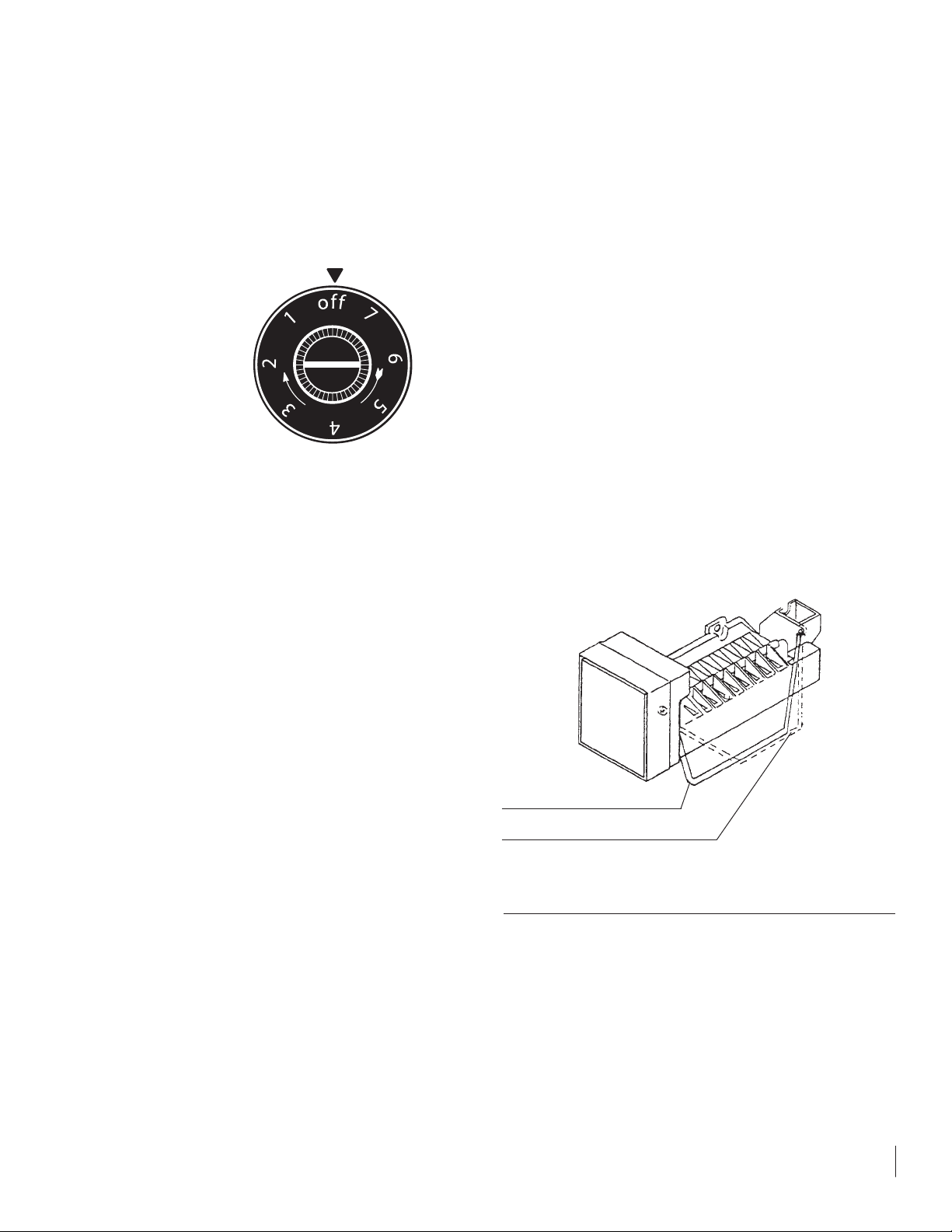
Temperature
Control and Selection
The temperature control knob is located in the grille
below the door. There is a pointer on the grille at the
12:00 position to indicate knob position.
The "OFF" position will
turn the refrigeration
system off. Positions 1
is the warmest setting
and setting 7 is the
coldest. Wait at least 2
hours between temperature adjustments
to find a temperature
that suits you.
The refrigerator section temperature of the unit can be
adjusted using the adjusting slide located in the left side
and rear of the refrigeration section. Turn in the cold
direction indicted to make the refrigeration section colder and the opposite to warm the refrigeration section.
Defrost
This units uses an electronic control system to control
both defrost and refrigeration functions. This feature
eliminates the inconvenience of manual defrosting of the
evaporator in normal conditions. If commodities or ice
accidentally clog the drip tray, the obstruction must be
removed for proper defrost performance. It is normal for
some water droplets to be left on the evaporator or drip
tray. These will refreeze and be removed in the next
defrost cycle.
Defrosting is factory set to run after the compressor has
run approximately 12 hours. For climates with high
humidity levels and/or repeated opening of the door, an
optional 6-hour compressor run time is already programmed into the control. Aswitch will have to be set at
the control for this change to take place (consult your
distributor or authorized service center).
A drip tray heater is located in the unit for proper
removal of condensation. The heater will remain on as
long as the unit is plugged in. The control knob will not
turn the heater off. Unplug or disconnect power to the
unit if you are planning to leave the unit off or unattended for extended periods of time.
Icemaker Operation
• Make certain water pressure is at least 20 psi and
no more than 120 psi and is turned on.
• The unit must be installed level for proper icemaker operation.
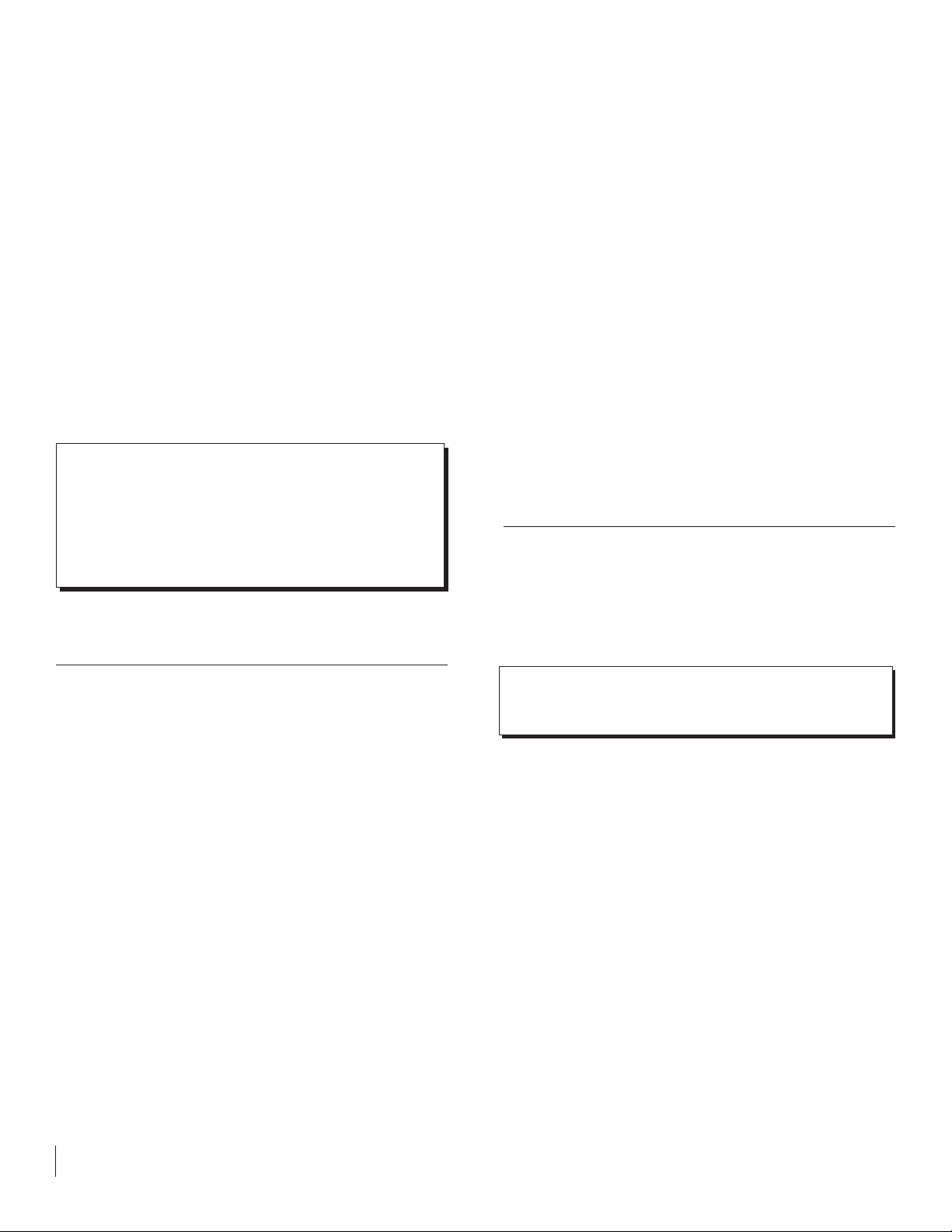
• The shut off arm wire must be down in its lowest
position for the icemaker to operate.
• Make certain there are no obstructions in the fan
inlet and outlet. The fan is located beside the icemaker at the top of the freezer section.
• When the freezer section and icemaker unit has
sufficiently cooled, the icemaker will harvest ice
cubes automatically.
• When the ice bucket is full, the icemaker will automatically shut off.
• You may manually stop the icemaker by raising
the shut-off arm to the locking position at the up
most position.
Important
When operation of the appliance is to be discontinued
for any length of time, the ice cube cavity in the icemaker should be emptied and dried. The water supply and
power supply should also be shut off and the ice bucket
should be emptied and cleaned.
If the ice is not used regularly, it will clump together with
time. For best ice results, discard ice in the bin as
required and allow the icemaker to make a new fresh
batch of ice.
2
Arm down, Icemaker will operate
Arm up, stops operation
C
R
O
E
L
D
Page 4
Unit care
• Avoid leaning on the cabinet and freezer doors.
You may bend the door hinge or tip the unit.
• Exercise caution when sweeping, vacuuming, or
mopping near the front of the unit. Damage to the
grille and/or light switch can occur.
• For cleaning of the appliance, mix a solution consisting of 2 tablespoons of baking soda with 1 quart
of warm water or use a mild soap. Do not use
strong cleaners or scouring powder or pads.
• Periodically empty ice bucket to replenish with
fresh ice.
Things to Remember
• Allow 24 hours for your refrigerator and freezer to
reach a new temperature setting.
• The unit will start and stop often. This is normal
operation of the unit.
• Keep your appliance level for proper icemaker
operation.
• Unplug the appliance before beginning any work to
the unit.
• The refrigeration section can be colder or warmer
using the adjusting slide located at the inside, left
rear section of the unit.
Interior Light
Your appliance also features an interior light. It uses a
15-watt appliance light bulb. To replace the light bulb:
1.Unplug the power cord from the wall receptacle.
Unless the unit is unplugged, the appliance light
system remains energized even with the control
knob in the "OFF" position.
2.Open the cabinet door.
3.Remove the 3 screws on the front face of the light
lens and remove the lens.
4.Unscrew the light bulb from the socket and replace
with an equivalent 15-watt, threaded intermediate
base appliance bulb.
5.Reassemble in the reverse order.
Electrical Fire Hazard
Under no circumstances replace with a bulb higher than
15 watts.
To clean the lens, disconnect the power cord and wipe
the lens with mildly damp cloth. Dry the lens and light
assembly completely before reconnecting the power cord.
3
Important: When operation of the appliance is
to be discontinued for any length of time, the ice
cube cavity in the icemaker should be emptied and
dried. The water supply and power supply should
be shut off and the ice bucket should be emptied
and cleaned.
Important: When operation of the appliance is
to be discontinued for any length of time, the ice
cube cavity in the icemaker should be emptied and
dried. The water supply and power supply should
be shut off and the ice bucket should be emptied
and cleaned.
Caution: Never pour liquids directly onto the
light assembly.
Caution: Never pour liquids directly onto the
light assembly.
Page 5
4
Door Features
There are many different door features available for
your new unit. Full panel overlay doors and full wrap
painted and stainless doors are available. These doors
are fully reversible.
To Reverse the Door Swing of the
Full Panel Overlay and Full Wrap Doors
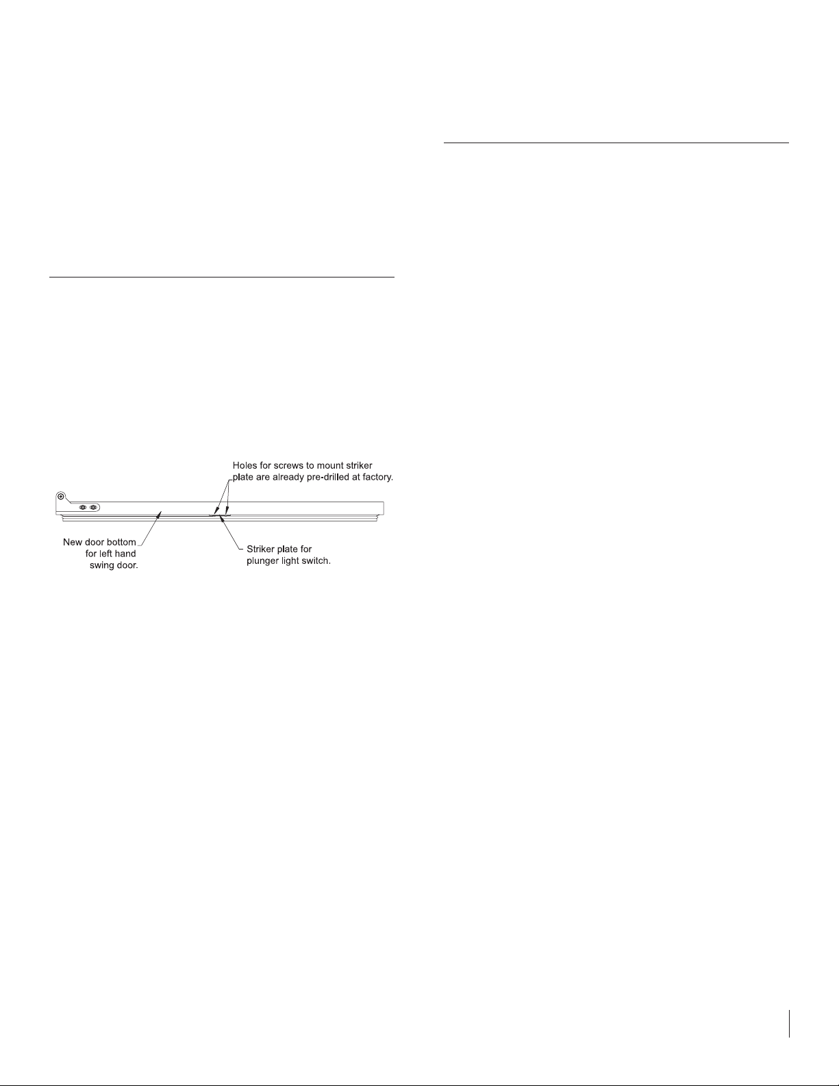
The door you relieved is for a right hand swing unit. If
the unit is to be changed to a left hand swing door, predrilled striker plate holes are in place on the backside of
the door on both ends. No additional drilling is necessary to mount the striker plate when you reverse the
door swing. Just unscrew the striker plate from the location it is mounted to for right hand swing and then
mount the striker plate at the end opposite of its previous location with the existing screws.
If your door has an inner door liner with formed in
shelves, it will need to be turned around for use in the
left hand swing. Using a small, flat blade screwdriver,
pop the plastic screw covers up to access the phillips
screws that secure the formed door liner to the door.
Using a phillips screwdriver, remove the phillips screws
that secure the formed door liner to the door. Rotate the
formed door liner 180 degrees, line up the mounting
holes in the door liner with the mounting holes on the
door. Use the existing fasteners and plastic screw caps
to secure the formed door liner to the door. Your door
swing conversion is complete.
Door Handle
The full wrap painted and stainless doors come with a
standard, vertically oriented tubular-style door handle.
This door handle has the same finish as the door it is
mounted on.
The full panel overlay doors are designed to receive a
custom supplied panel. The customer will need to supply the door handle that will be mounted to the customer
supplied panel.
Page 6

Before Calling for Service
Check and test the electrical outlet's fuse or breaker.
Make certain the control knob in the grille is not in the
"OFF" position.
The unit may be in the “off” portion of the refrigeration
cycle. This is typical. Wait to see if the unit cycles back on.
Look back in the grille for a green LED light. If the con-
trol knob is on, the LED will not blink. If the LED is blinking, the unit is in the "OFF" position or there is a faulty
input (contact dealer or servicer for faulty input).
For further questions or service, refer to the dealer or
manufacture. In any correspondence, refer to the model
serial number (located on the lower front cabinet flange
above the grille), a description of the problem or question, and proof of purchase.
Things to remember
•Allow 24 hours for your refrigerator and freezer to
reach a new temperature setting.
•The unit will start and stop often. This is normal operation of the unit.
•Keep your appliance level for proper icemaker operation.
•Unplug the appliance before beginning any work to
the unit.
•The refrigeration section can be colder or warmer
using the adjusting slide located at the rear of the unit.
Help Prevent Tragedies
Each year children die because they climb inside a
discarded refrigeration product, get trapped inside
and suffocate. Take precautions to prevent such
tragedies by removing the door, taping or chaining it
shut before discarding.
How to Obtain Service
Your unit requires little service because of the best
and most up-to-date materials, equipment and quality
control methods are employed throughout the manufacturing process.
If trouble occurs, first check the troubleshooting section
to see if the problem can be corrected. If service
becomes necessary:
Contact the dealer where you purchased your appliance
or the manufacturer for the name of your nearest authorized service representative. The service representative
will have authority to make repairs deemed necessary.
If you are in an area where there are no service representatives, write or call the manufacturer directly. We
will make recommendations as to proper procedure for
correction. Service work and replacement parts, if
required, will be provided as covered by your limited
warranty.
In all correspondence regarding service, be sure to give
the model number, serial number, and proof of purchase.
It is important that you send in your warranty card
immediately after taking delivery of your appliance.
Normal Responsibilities
of the Owner Include
• All freight charges.
• Damage sustained in transit (See page 1).
• Mileage charge(s) for service calls.
• Proper installation, proper water hook-up, and proper electrical supply.
• Alterations to original equipment.
• Removal or installation of additional equipment.
5
Page 7
If You Do Need Service
In the event that you do need service, be sure to report the
model number, serial number and proof of purchase to your
service representative. Model number and serial number
are found on the serial plate which is located on the lower
front cabinet flange. For your convenience you may want to
record the following information for your records.
Date of purchase
Dealer’s Name
Dealer’s Address
Dealer’s City
Dealer’s State Zip
Appliance Serial Number
Model Number
Date Warranty Card Sent (Must be within 10 Days of Purchase)
Five-Year Limited Warranty
This limited warranty is given by the manufacturer (herein after referred to as the Company) to the original purchaser of the equipment supplied by the Company as
long as the equipment remains the possession of the
original purchaser.
First Year of Limited Warranty
The mechanical system of you refrigerator is warranted against defects in workmanship or material for a
period of one year from date of purchase under the
following provisions:
Warranty card must be filled in and mailed back to the
Company within 10 days from the purchase date.
Defects must be proven to the satisfaction of the
Company to have been caused by defects in workmanship or material. It may be requested that defective parts
be returned to the Company for inspection at the purchaser's expense.
The owner is responsible for all items as detailed as the
normal responsibilities of the owner.
In-warranty repair should be performed by factory
authorized service centers. If there is no service center
in your area, contact your dealer of the manufacturer. Inwarranty repair charges not authorized by the Company
will be payable at the Company's discretion.
Additional 2nd Through 5th
Year Limited Warranty
During the four years following the First Year Limited
Warranty, the company will supply replacement parts for
the sealed refrigeration system that are proven to the
Company's satisfaction to be defective due workmanship or material. Other parts, labor costs, and freight
charges will be the responsibility of the owner.
IN NO EVENT SHALL THE COMPANY BE LIABLE FOR
INCIDENTAL OR CONSEQUENTIAL DAMAGES
INCLUDING, BUT NOT LIMITED TO, CONTENT LOSS.
Some states do not allow limitations on length of time
implied warranty may last, so the above limitations may
not apply to you.
This warranty gives you specific legal rights. You may
also have other rights which very from state to state.
6
Page 8
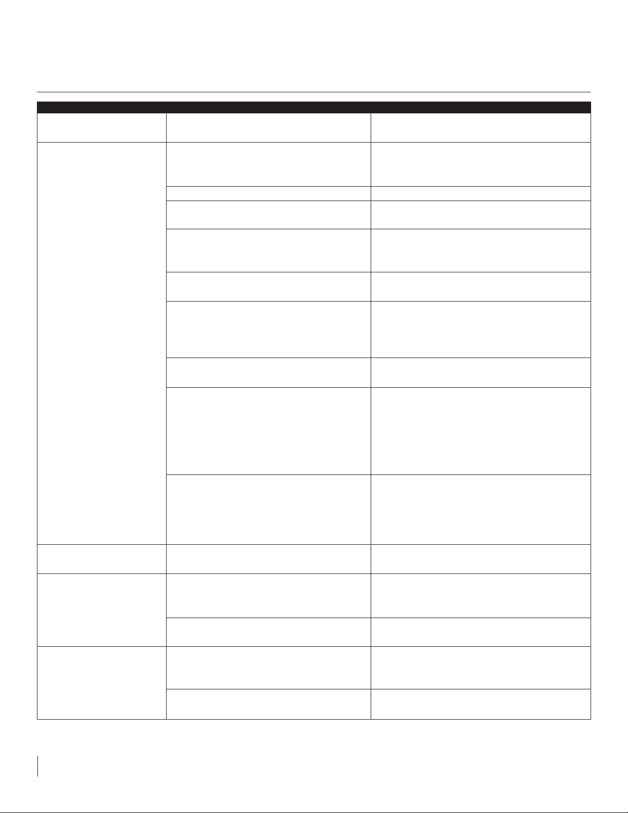
PROBLEM
Odor in the cabinet
Unit operates but does not
produce any ice.
Small ice cubes
Noisy operation
Ice cubes are sticking
together.
POSSIBLE CAUSE
The unit needs to be cleaned.
The unit has just been started and it has
been less than 24 hours.
Water supply is not turned on.
Inadequate water pressure to unit
The icemaker shut-off arm is in the
uppermost position.
Freezer section has not reached
temperature.
Thermostat control knob set too warm.
Blower inlet and/or outlet is restricted.
Condenser fan air flow is restricted.
Room and/or water temperature is too
warm.
Water input may require adjustment
Cabinet not level
Weak floor structure
Water line tubing vibration
Ice consumption is low.
Room temperature is too warm.
CORRECTION
Clean the interior using a solution of baking
soda and warm water or water and mild soap.
Typical ice production is 2 lbs per day. Allow
for the freezer section to reach temperature
and the icemaker to cycle and accumulate ice.
Turn on water supply to the unit.
Water pressure to the unit must be at a
minimum of 20 psi.
When the icemaker shut-off arm is in the
uppermost position, the icemaker is off. Flip
the shut-off arm down to turn on the icemaker.
Allow the freezer section to reach temperature.
Turn the temperature control knob to a higher
number to allow the unit to run colder. Allow 24
hours before readjusting the temperature
control.
Keep blower area clear from commodities for
proper operation.
Make certain the grille in the front of the unit is
free and open for proper air circulation. Check
and clean the condenser coil by removing the
grille in the front of the unit. Clean the
condenser with a vacuum and brush
attachment.
Move the unit to an area where ambient
temperature is below 90 deg. F. The unit
should not be placed next to a heat source
such as an oven. Check for cold water
connection.
Due to differing water pressures, the icemaker
water input may require adjustment.
Adjust the leveling legs on the unit.
The unit must be located on a sound and
sturdy floor for proper operation
Adjust the tubing as necessary to prevent
unwanted vibrations.
Use the ice in the bin frequently. Ice will stick
together if left in insulated bin over long
periods of time.
Move the unit to an area where temperature is
below 90 deg. F.
Trouble Shooting One
7
Page 9
8
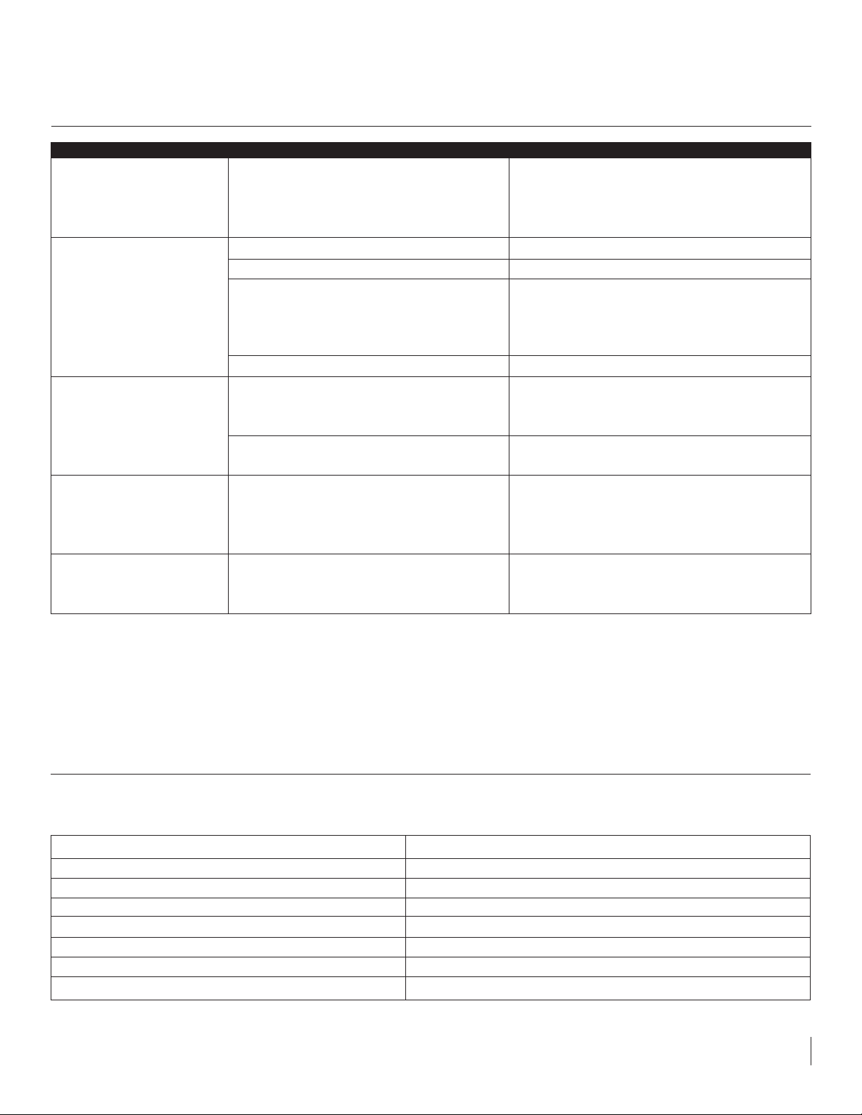
PROBLEM
Moisture collects on
outside surface of cabinet.
Moisture collects on inside
of the unit.
The unit is too warm or too
cold.
The unit is warm inside
with the temperature
control know in the “OFF”
position.
Items on door shelf
sometimes freeze.
POSSIBLE CAUSE
Hot and humid conditions.
Too many door openings.
Prolonged door openings.
Hot and humid conditions.
Defrost thermistor out of specification.
Adjustment of the temperature control
knob.
Temperature control slide in the
refrigerator section too far open.
Drip tray heater is on.
The upper two shelves of the door can
freeze under warm conditions.
CORRECTION
Extremely hot and humid conditions can cause
condensation on the outside of unit. As
humidity and/or temperature decreases,
condensation will disappear.
Limit the amount of door openings.
Limit the amount of time with the door open.
Extreme hot and humid conditions. Move unit
to a controlled environment. May consider
having the defrost section changed from 12 to
6 hours.
Consult dealer or servicer for diagnosis.
Adjust the temperature control to warmer or
colder setting and allow 24 hours before
readjusting if necessary.
Adjust temperature control slide as necessary
in the refrigerator section of the unit.
The drip tray heater will remain energized with
the control knob in the off position. Unplug the
unit if storing or leaving the unit off for
extended periods of time.
Turn the temperature control knob to a lower
number or move the commodities to the
refrigerator section.
Trouble Shooting Two
Diagnostic LED
In the back in the grille there is a diagnostic/status LED. This led is used to help diagnosis any problems with the unit
and to tell its status.
LED status
Not on or blinking
steadily blinking once per second
Continuously on
2 blinks and pause; repeated pattern
3 blinks and pause; repeated pattern
4 blinks and pause; repeated pattern
2 blinks, pause, 3 blinks, pause; repeated pattern
Code/Problem
Unit does not have power
Unit temperature control is in the "OFF" position
Unit is "ON" and operating correctly
Defrost thermistor out of range
Evaporator normal cycling thermistor out of range
Control potentiometer out of range
Both defrost and evaporator thermistor are out of range
Page 10
Notes
9
Page 11
10
Notes
Page 12

41008536 Rev B
www.marvelindustries.com
Phone: (765) 962-2521 Fax: (765) 962-2493
Marvel Industries
Part of AGA Foodservice Group
233 Industrial Parkway
P.O. Box 997
Richmond, IN 47375-0997
 Loading...