

Page 1

Marvel Ice Machine
Installation
Operation &
Maintenance
Instructions
Part of AGA Foodservice Group
Page 2

Remove Packaging
Your ice machine has been packed for shipment
with all parts that could be damaged by movement
securely fastened. Before installing the ice
machine, be sure all packing materials and tape
have been removed.
Important
Save the carton packaging until your ice machine
has been thoroughly inspected and found to be in
good condition. If there is damage, the packaging
will be needed as proof of damage sustained in
transit.
Note to Customer
This ice machine was carefully packed and thoroughly inspected before leaving our plant.
Responsibility for its safe delivery was assumed by
the carrier upon acceptance of the shipment. As
directed on the side of the packaging carton,
claims for loss or damage sustained in transit must
be made on the carrier as follows:
Exterior Damage
Make a thorough damage notation on the delivery
receipt and have the driver acknowledge by signing and dating. Send a written request asking for
an inspection report from the carrier representative
and the date the inspection was requested. Retain
the inspection report and receipt for filing of a
claim.
Concealed Damage
This must be reported to the carrier within fifteen
days. Obtain an inspection report from the carrier.
Retain the inspection report for filing of the claim.
DO NOT RETURN DAMAGED MERCHANDISE
TO THE MANUFACTURER - FILE THE CLAIM
WITH THE CARRIER.
1
STARTING OUT
Page 3
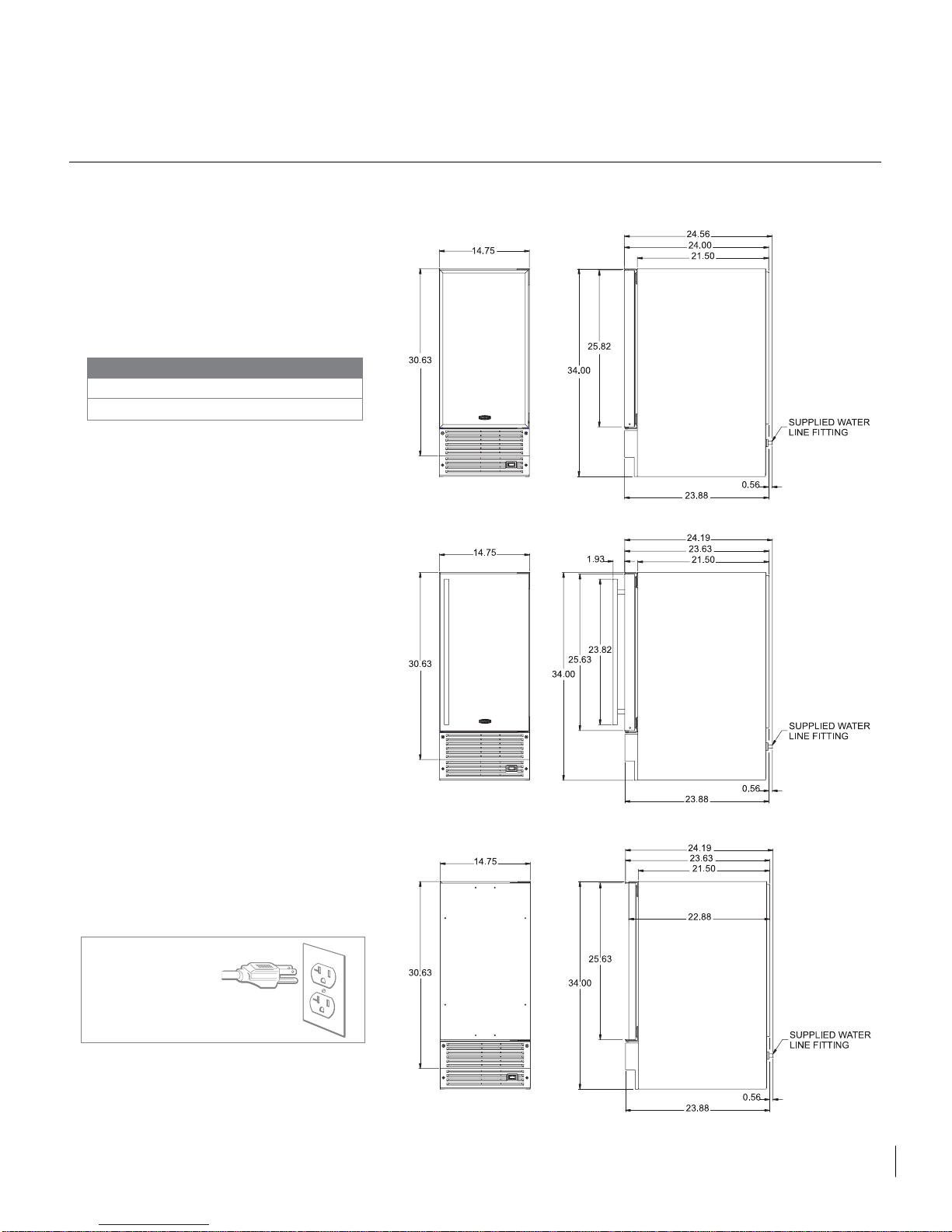
Select Location
The proper location will ensure peak performance of your ice machine. Choose a location
away from heat and out of direct sunlight. Best
performance will be maintained when installed
within the following parameters:
Cabinet Clearance
Ventilation is required for the bottom front section
of the unit where the grille is located. Keep this
area open and clear of any obstructions.
Adjacent cabinets and countertop can be built
around the unit as long as no top trim or countertop is installed lower than the top of the hinge.
Make certain that the glides supplied with the ice
machine are installed according to instructions.
Make certain your ice machine is level. Leveling
adjustments can be made by raising or lowering
the glides on the bottom of the unit.
Electrical Connection
Check the serial nameplate for the correct power
supply. Use only the electrical power supply
specified on the serial nameplate. Do not use an
extension cord.
Grounding Method
This ice machine is equipped with a power supply
cord with ground. It must be plugged into a mating
grounding type receptacle in accordance with the
National Electrical Code and applicable local
codes and ordinances.
THIS UNIT SHOULD NOT, UNDER ANY
CIRCUMSTANCES, BE UNGROUNDED.
2
INSTALLATION
Ideal Ambient Temperature Range*
built-in
freestanding
* Ice Machine will not perform correctly in ambient temperatures less than 55°F.
55-80°F
55-90°F
RPE style door
Note: The plug shown is
for 115VAC unit. The
prongs on your model
may vary from that
shown if your unit is
other than 115VAC.
Full Wrap
Style Door
Overlay/Designer
Style Door
Page 4
Drain Plumbing
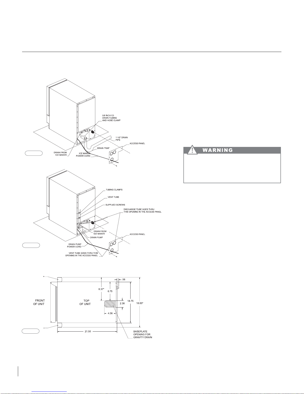
Your ice machine uses a gravity drain, (figure 1)
that requires 5/8" I.D. tubing from the back of the
ice machine to a plumbed connection to a sanitary
sewer. Remove the access panel to plumb in drain
connection. Gravity drain location for built-in units
can be within the area shown in figure 3. An optional drain pump, (figure 2) can be purchased for your
ice machine if a gravity drain is not accessible.
OBSERVE AND FOLLOW ALL LOCAL CODES
WHEN INSTALLING ICE MACHINE.
3
INSTALLATION: DRAIN PLUMBING
Gravity Drain Location
* With optional filler kit
FAILURE TO USE ADEQUATE DRAINAGE
SYSTEM WILL RESULT IN SURROUNDING
WATER DAMAGE AND/OR POOR ICE
PRODUCTION.
figure 1
figure 2
figure 3
Page 5
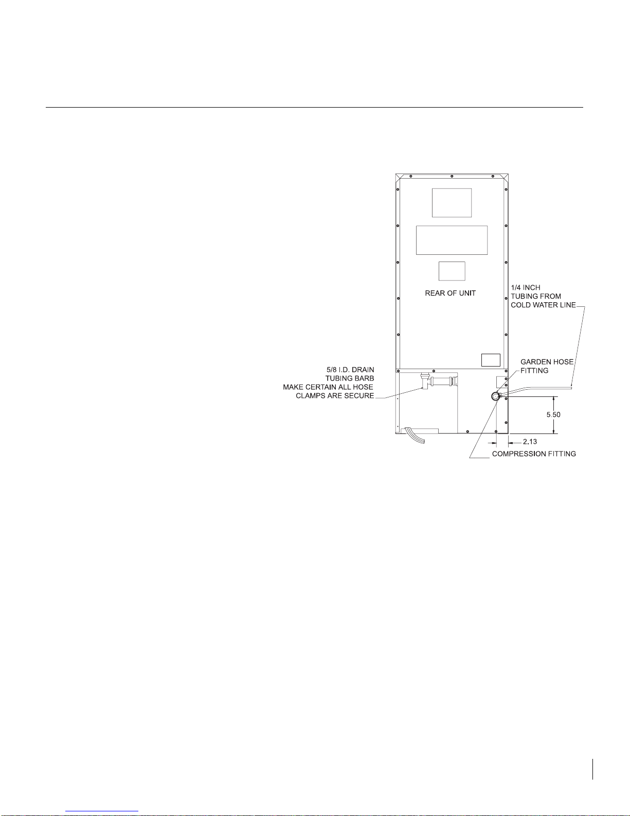
Water Supply
This ice machine must be connected to a potable,
active cold water supply line delivering water
pressure at a minimum of 20 psi and maximum of
120 psi.
• Water connection is made through a right angle
garden hose fitting. See garden hose fitting for
detailed instruction sheet.
• A water filter is recommended for this unit. A
quality filter can remove particles as well as
remove taste and odors from water. Do not use
any thread sealers.
• Softened water is not recommended. This will
produce mushy, cloudy ice cubes that will stick
together.
• De-ionized water is not recommended. This
water will not form solid ice cubes.
• Awater specialist can recommend proper water
treatment.
• After installation of water line, turn on water and
check for any leaks. Additional tightening may be
needed.
• Allow for extra water line for built-in installations
for easy removal of unit and to help prevent the
water line from kinking.
Operation
Your ice machine is unique in forming ice. It uses
fractional freezing to form a slab of ice that is clear
and has less mineral content than the water it is
produced from. This is accomplished by running
water over the cold evaporator plate which gradually freezes the water to produce the ice slab. Mineral deposits are left in the reservoir.
When the ice slab reaches the correct thickness
determined by the temperature of the evaporator
plate, the electronic control switches to the harvest cycle to harvest the ice. During the harvest
cycle, the ice slab falls from the evaporator to the
ice grid cutter. Here, the ice slab is cut into 3/4"
squares by the grid cutter's heated wires. During
the harvest cycle, the drain valve will remain open
for 45 seconds to drain the reservoir of remaining
deposits. After that, the water valve open will open
for 2 minutes providing 2 quarts of water to the
reservoir for the next ice production cycle.
The ice machine will keep producing ice until the
ice machine's bin is full and will restart automatically when ice needs to be replenished in the bin.
4
WATER SUPPLY
Page 6

5
CARE OF THE UNIT
Care of Unit
1. Avoid leaning on the cabinet door. You may
bend the door hinge or tip the unit.
2. Exercise caution when sweeping, vacuuming,
or mopping near the front of the unit. Damage
to the grille and/or switch can occur.
3. Periodic cleaning of the inside of the ice
machine components and inside of unit (see
Cleaning Your Ice Machine section).
4. Periodic checking and/or cleaning of the front
grille and condenser coils as needed.
Normal Responsibilities of the Owner
• All freight charges
• Damage sustained in transit
• Mileage charge(s) for service calls
• Proper installation including installation of leveling legs.
• Leveling of unit.
• Alterations to original equipment
• Removal or installation of additional equipment
(i.e. drain pump).
• Cleaning and normal maintenance outlined in
this manual.
• Drain and water supply plumbing to the ice
machine.
Help Prevent Tragedies
Each year, children die because they climb inside
a discarded refrigeration product, get trapped
inside and suffocate. Take precautions to prevent
such tragedies by removing the door, taping or
chaining it shut before discarding.
Page 7
Cleaning Your Ice machine
Some impurities will remain and build-up in the ice
machine and stick to the ice machine's parts over
time. This build-up must be removed for proper ice
production, ice quality, and ice machine life. Your
ice machine is equipped with a cleaning mode that
will help in cleaning out these impurities.
The impurities will regularly (at the very least,
annually) need to be cleaned of this build-up,
depending on use and water hardness. You can
use an acid such as one specified for ice machine
cleaning or you can use citric acid to remove the
build-up. To clean the ice machine:
1. Switch the selector switch to the "OFF"
position.
2. Remove the drain plug at the bottom of the
reservoir to drain any remaining water and
then reinstall.
3. Add the recommend cleaner solution to the
reservoir of the ice machine. Access to the
reservoir can be obtained by removing the
front panel screws and the front panel.
Determine to proper amount of cleaner from
the ice machine cleaner manufacturer's mixture ratio based on 3 quarts of water (refer
to manufacturer's directions).
4. Replace the front cover panel and close the
door.
5. Switch the selector switch on the grille of the
ice machine the clean position. Three quarts
of water will automatically be added to the
cleaning solution.
6. The total cleaning time will end in 49 minutes. The cleaning cycle will automatically
rinse the evaporator plate and also drain the
cleaning solution and rinse water.
7. After the cleaning cycle has ended, remove
the front panel again and check that the
build up has been removed. The evaporator
plate should be clean, shiny, and smooth to
the touch. If build up is still visible, repeat
the cleaning cycle above. If build up is
removed, continue below.
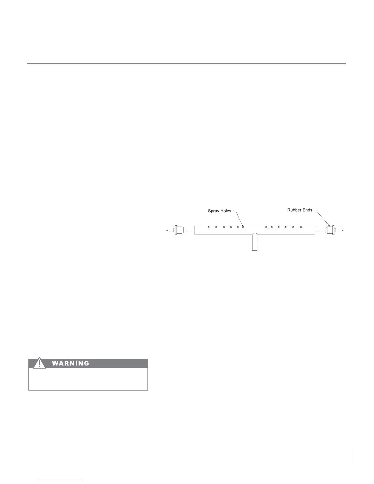
8. Remove the distributor tube, hose clamp,
hose and its rubber ends.
9. Thoroughly clean the inside of the distributor tube and the spray holes. You can use
the same cleaning solution as before and an
old toothbrush to reach the inside of the distributor tube.
10. Reinstall the rubber ends, hose, and hose
clamp to the distributor and then reinstall the
distributor tube to the evaporator with the
spray holes pointed to the bottom of the
evaporator plate. Reinstall the front cover
panel with the two front panel screws.
11. Clean the ice machine's interior, ice scoop,
interior door panel and door gasket with mild
soap and water. Using two tablespoons of
baking soda in one quart of warm water
while cleaning will help remove odors. Rinse
with fresh water. Do not use any abrasive
cleaning products.
Your ice machine is now clean and sanitized and
may be put back into operation by switching the
selector witch to the "ON" position.
6
CARING FOR YOUR ICE MACHINE
Read manufacturer's warnings on ice machine
cleaner products. Personal injury can result.
Page 8
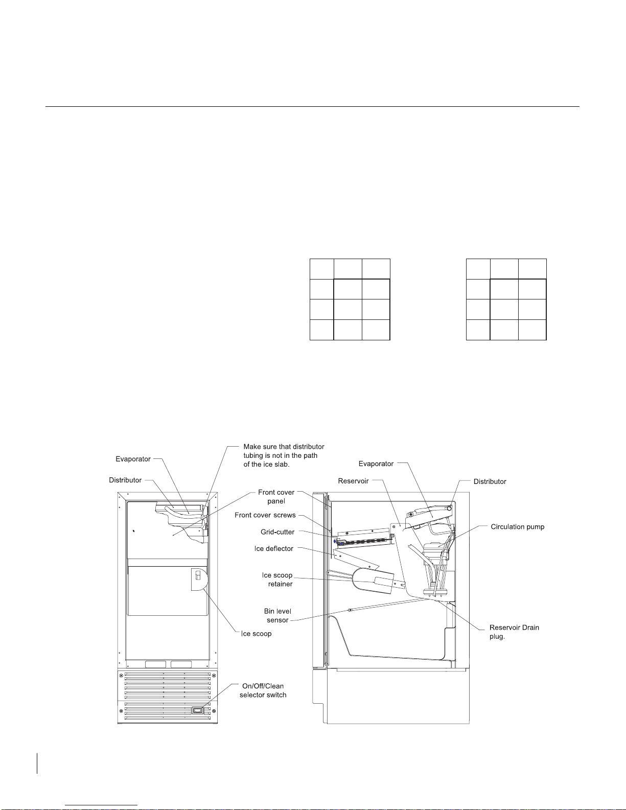
7
THINGS TO REMEMBER
Things to Remember
• Allow your ice machine to run for 24-48 hours to
accumulate ice in ice machine's bin.
• Unit will cycle often between ice production and
ice harvest cycles.
• Your unit will automatically shut down when the
ice bin is full.
• Unplug your ice machine before working on
unit.
• Keep your ice machine clean for proper ice
quality, production, and unit life.
• Room and water temperatures will greatly
affect the output of ice in your unit (see table).
Ice will also melt away, especially at the start
of an empty bin, but will slow down as ice
accumulates.
PRODUCTION RATE
(LB/DAY)*
APPROXIMATE TIME TO FILL
BIN (HOURS)*
WATER TEMPERATURE °F
50
70
70
34 32
30 27
80
23 20
90
ROOM TEMPERATURE °F
*NOTE: DUE TO VARIABLES IN INSTALLATION AND USE, INDIVIDUAL RESULTS MAY VARY.
WATER TEMPERATURE °F
50
70
31
41
80
60
90
ROOM TEMPERATURE °F
70
34
58
82
Page 9

Optional Door Handle Installation
(for units without door handle attached)
The door handle for certain doors may be packed
inside your ice machine can be mounted on the
top or side of your refrigerator door. Locate the
handle where it is convenient for you. You will
need a 1/4" hex head driver to install the handle.
Place the handle on the outside surface of the
door. Push gently inward toward the door until the
handle snaps in place. Use the two screws supplied to secure the handle to the door frame by
tightening the screws into the holes on the backside of the handle. Tighten the screws until the tips
of the screws touch the bottom of the backside of
the door frame. Your installation is complete.
Reversing the Door
You may want to change the side on which the
door opens and closes. This can be changed by
the following steps.
1. Remove the door by removing the top hinge
pin and angling the door off of the bottom
hinge pin.
2. Gently pry out the hole plugs on the side
which the hinges will be mounted. A thin
knife will usually allow the hole plug to be
removed just enough to pull the rest of the
way out by hand. Do not destroy these plugs
because they will be used on the other side
of the unit.
3. Remove the hinges from the unit.
4. Remove the hinge pin from the bottom hinge
that was removed. Install this pin on the
other hinge that was also removed.
5. Install the hinges on the desired side of the
unit.
6. Install the door by inserting the bottom door
bushing with the bottom hinge pin and
angling door in until top door bushing and
hinge line up. Install the upper hinge pin.
7. Install the hole plugs from step 2 in holes.
DOOR ALTERATIONS
8
Page 10
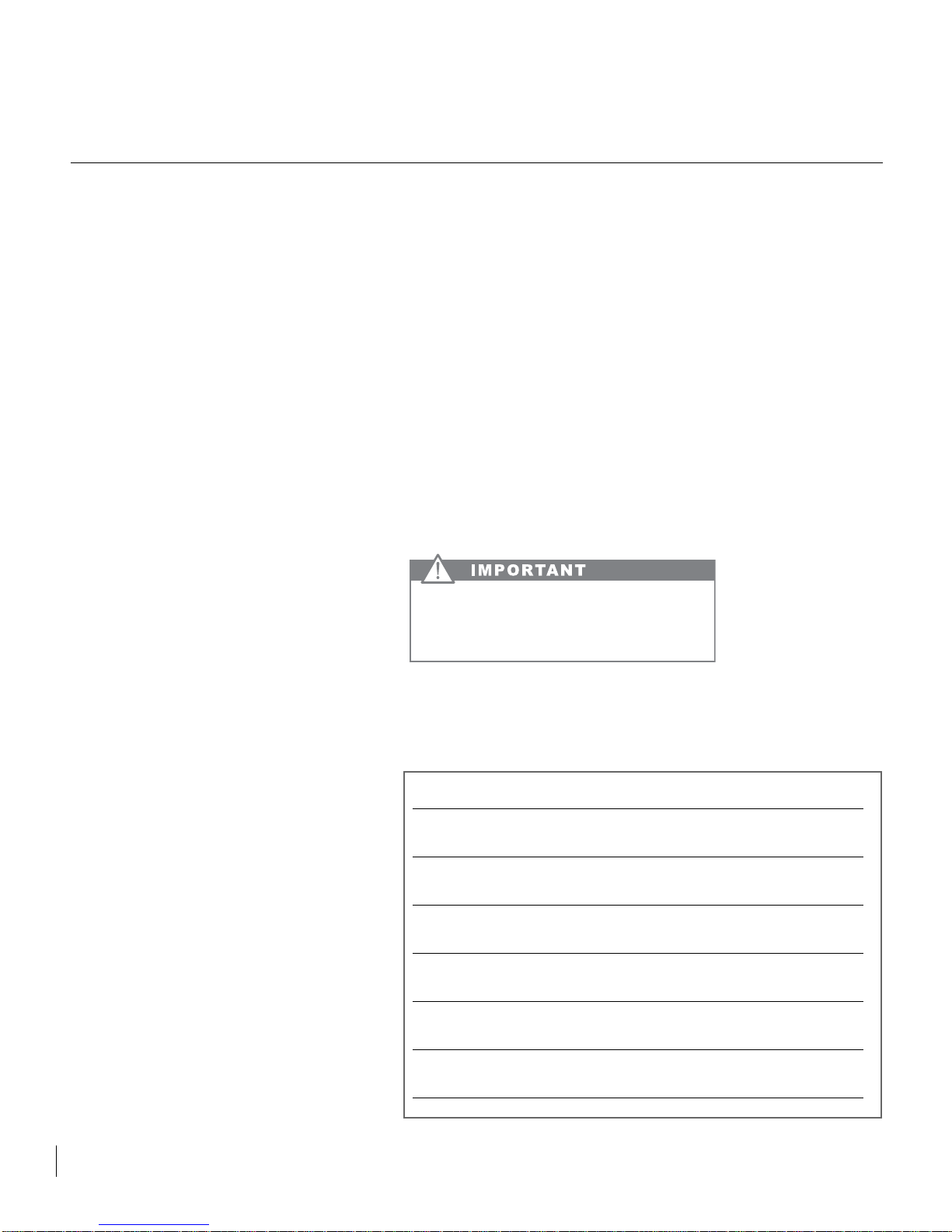
Before Calling for Service
Before calling for service, check the following
items:
• Make sure unit is plugged into outlet.
• Check the outlet for power. Test outlet with
lamp to make certain outlet has power.
• Make sure ice machine's switch is in the "ON"
position.
• Make sure that there is cold water supplied to
the ice machine.
• Make sure drain plug on bottom of reservoir
is inserted.
• Make certain unit is level from front to back
and side to side.
• Make certain that the drain line to the ice
machine is unrestricted or kinked.
• Use troubleshooting guide, pages 11-14 for
other diagnosis.
If you are not able to correct the problem, contact
your dealer or the manufacturer. Be sure to have
the model number and the serial number handy
before you call. The model and the serial number
are located on the lower front part of the ice
machine's cabinet.
How to Obtain Service
Your ice machine requires little service because
the best and most up-to-date materials, equipment and quality control methods are employed
throughout the manufacturing process.
If trouble occurs during normal operation, read
"Things to remember" section first and, if necessary, check the troubleshooting guide. If service
becomes necessary:
1. Contact the dealer where your appliance
was purchased or the manufacturer for the
name of the nearest authorized service representative. The service representative will
have full authority to make any repairs
deemed necessary.
2. If you are in an area where there is no service representative, write or call the manufacturer directly. We will make recommendations as to the proper procedure for correction. Service work and replacement parts, if
required, will be provided as covered by your
limited warranty.
3. In all correspondence regarding service, be
sure to give the model number, serial number and proof of purchase.
4. Try to have information or description of the
nature of the problem, how long the unit has
been running, the room temperature, water
temperatures, and any additional information that may be helpful in quickly solving the
problem.
Every new ice machine that leaves the factory
contains this Owner's Guide. Keep this Owner's
Guide in a safe place for convenient reference.
For Your Records
OBTAINING SERVICE
SEND IN YOUR WARRANTY RECORD
CARD IMMEDIATELYAFTER TAKING
DELIVERY OF YOUR ICE MACHINE.
9
Date of Purchase
Dealer’s Name
Dealer’s Address
Dealer’s city Dealer’s State Zip
Appliance Serial Number
Model Number
Date Warranty Card Mailed (within 10 days of purchase)
Page 11

Entire Product
Limited One Year Parts and Labor Warranty
Marvel warrants that it will supply all necessary
parts and labor to repair or replace in the end
user's home or office, any component which
proves to be defective in material or workmanship,
subject to the condition and exclusions stated
below, for a period of one year from the date of
purchase by the end user.
Additional Second Through Fifth Year
Limited Parts Only Warranty
During the four years following expiration of the
one year limited warranty, Marvel will supply
replacement parts for the hermetically sealed
refrigeration system which consists of the compressor, condenser, drier, accumulator, by-pass
valve, connecting tubing and the evaporator that
are proven to be defective due to workmanship or
materials subject to the conditions and exclusions
below.
The above warranties do not cover:
• Shipping costs of replacement parts or returned
defective parts.
• Customer education or instructions on how to
use the appliance.
• Any content loss due to product failure.
• Removal or installation.
Nor do the above warranties cover failure of this
product or its components due to:
1. Transportation or subsequent damages.
2.Use commercially or use other than normal
household or small office.
3.Improper installation, misuse, abuse, accident
or alteration, use on wiring not conforming to
electrical codes, low or high voltages, failure to
provide necessary maintenance, or other unreasonable use.
Parts or Service
Not Supplied or Designated by Marvel
The above warranties also do not apply if:
The original bill of sale, deliver date or serial num-
ber cannot be verified.
Defective parts are not returned for inspection if so
requested by Marvel.
The refrigeration equipment is not in the posses-
sion of the original end use purchaser.
The warranties set forth herein are the only war-
ranties extended by Marvel Industries. Any implied
warranties, including the implied warranty of merchantability, are limited to the duration of these
express warranties. In no event shall Marvel
Industries be liable for any consequential or incidental damages or expenses resulting from
breach of these or any other warranties, whether
express or implied.
Some states do not allow the exclusion or limitation of consequential damages or a limitation on
how long an implied warranty lasts, so the above
exclusion or limitation may not apply to you. This
warranty gives you specific legal rights and you
may have other rights that may vary from state to
state.
No person, firm, or corporation is authorized to
make any other warranty or assume any other
obligation for Marvel Industries. These warranties
apply only to products used in any of the fifty
states of the United States and the District of
Columbia.
To obtain performance of this warranty, report any
defects to:
Marvel Industries
P.O. Box 997
Richmond, Indiana 47375-0997
Phone: 765-962-2521
10
WARRANTY
Page 12
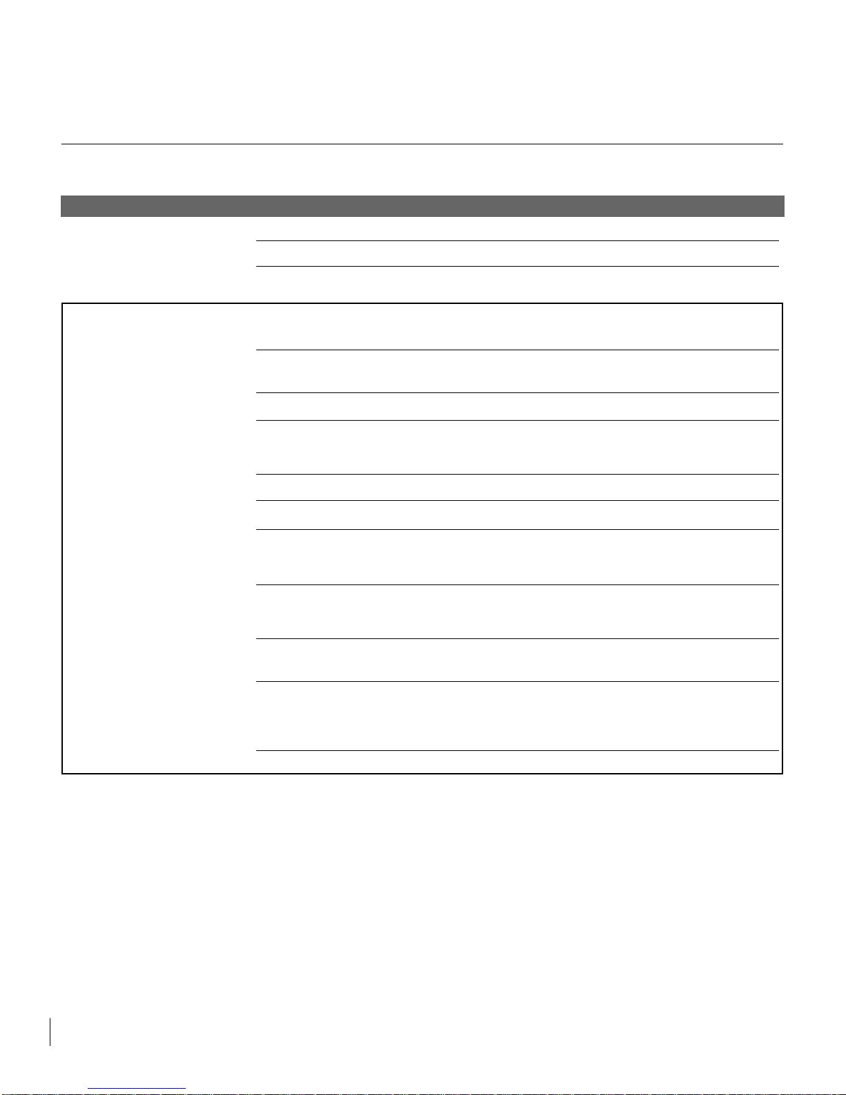
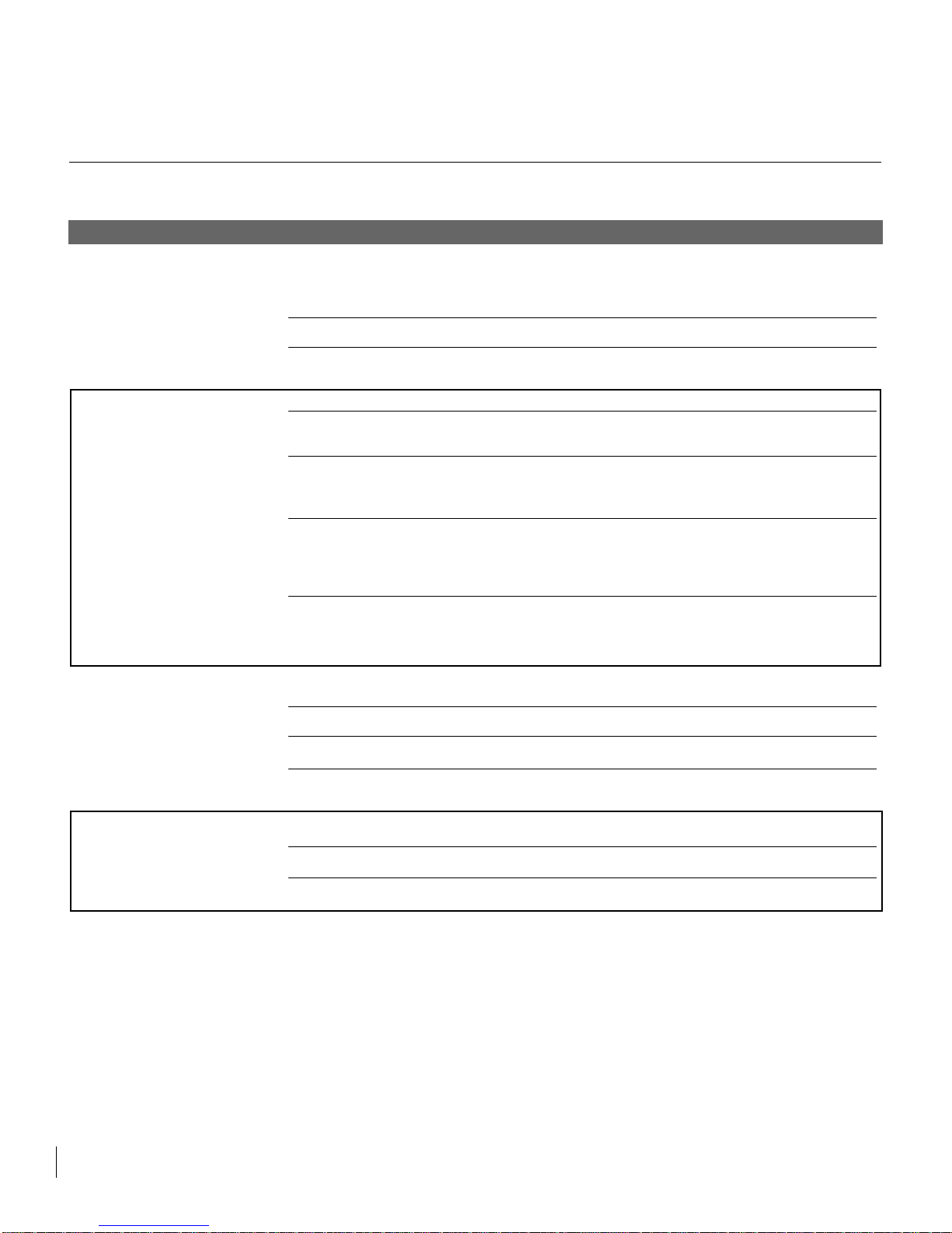
PROBLEM
Unit does not operate.
Unit operates but does not produce
any ice.
TROUBLESHOOTING ONE
11
POSSIBLE CAUSE
The unit is unplugged.
Breaker is tripped or fuse is blown.
Ice machine selector switch is in the "OFF"
position.
The unit has just been started and it has
been less than 6 hours.
Typical ice production cycle can take up to
1.5 hours. Initial startup cycles can be
longer.
The selector switch is in the "OFF" or
"CLEAN" position.
No water in the reservoir.
Distributor tube is restricted.
Build up of deposits on evaporator plate.
Condenser fan air flow is restricted.
Room and/or water temperature is too
warm.
Leaking drain valve.
Inadequate drain system.
Grid cutter is unplugged.
CORRECTION
Plug in the unit.
Reset breaker or replace fuse. Check to make sure there is
not a short in the electrical circuit.
Set the rocker switch on the grille of the ice machine to the
"ON" position.
Ice produced when the unit is initially started will melt off in
the bin. Ice will accumulate in the bin. In 6 hours there can
be a few cubes in the bin. This is normal operation.
Check the unit in 24 hours for ice accumulation in the bin.
Set the rocker switch on the grille of the ice machine to the
"ON" position.
Make sure that the reservoir drain plug is installed. Check
the water line to the unit to make sure it is on and that there
are no restrictions or kinks in the line. Check all filters to
make sure they are not restricted or plugged.
See "CLEANING YOUR ICE MACHINE" section for cleaning the unit for proper operation.
See "CLEANING YOUR ICE MACHINE" section for cleaning the unit for proper operation.
Make certain the grille in the front of the unit is free and
open for proper air circulation. Check and clean the condenser coil by removing the grille in the front of the unit.
Clean the condenser with a vacuum and brush attachment.
Move the unit to an area where ambient temperature is
below 90 deg. F. The unit should not be placed next to a
heat source such as an oven. Check for cold water connection.
See "CLEANING YOUR ICE MACHINE" section for cleaning the unit. This will also dissolve and flush out foreign
material in the drain valve causing it to leak.
Restriction in drain lines will cause ice in the bin to melt. If
using a gravity drain, make certain there are no kinks or
restrictions in the drain lines. If using a drain pump, check
the inlet screen, discharge line, and vent line for any build
or restrictions.
Plug in the grid cutter so that ice slabs can be cut into cube.
Page 13
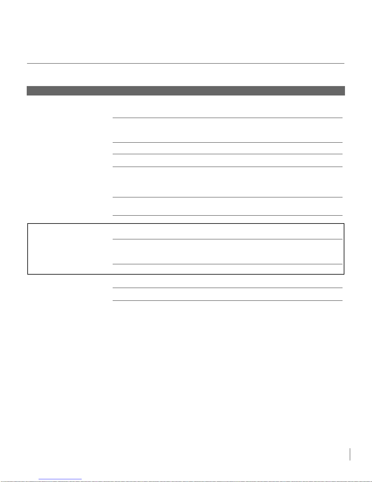
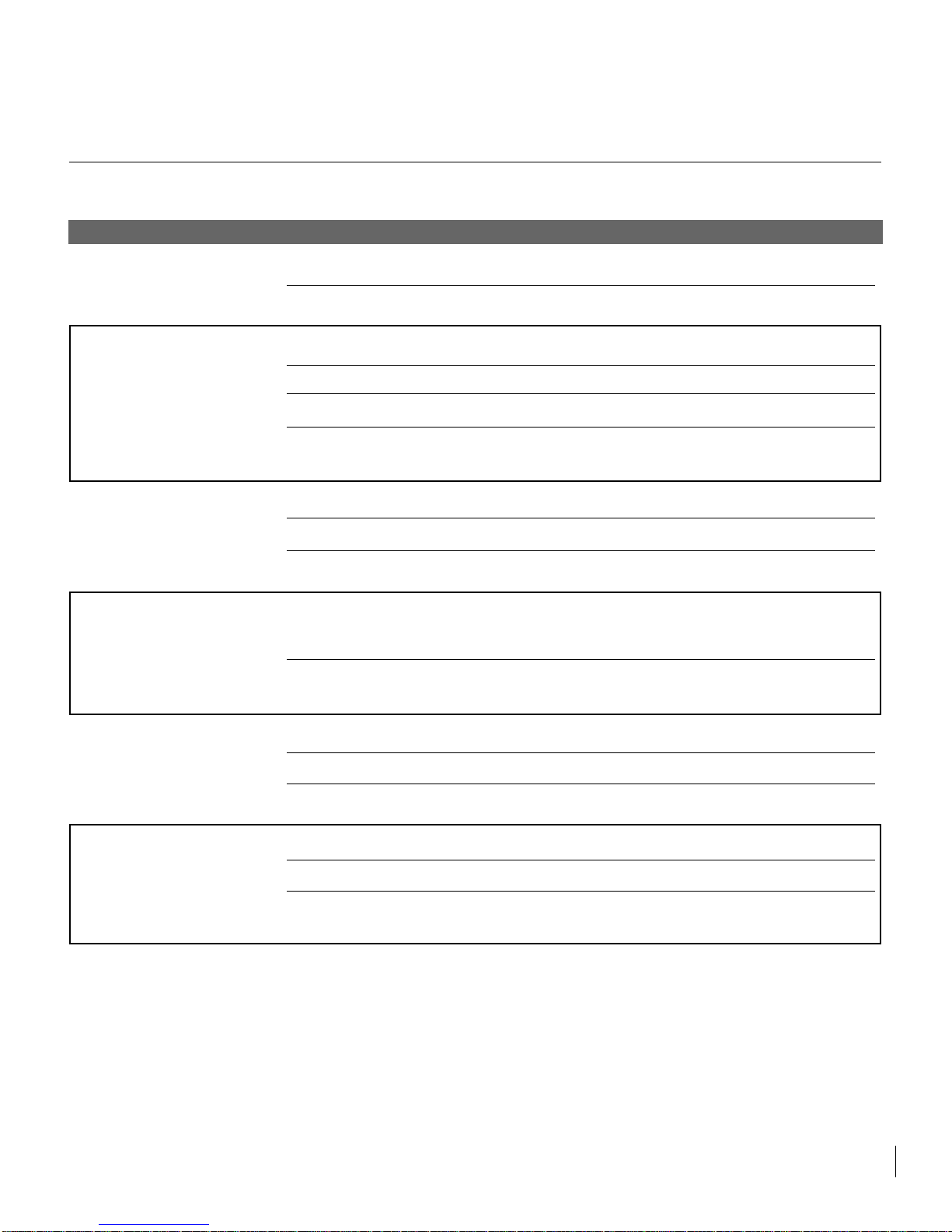
PROBLEM
Ice cubes are too small (less than
1/2 inch thick).
Ice cubes are too big (greater than
3/4 inch thick).
Hollow ice slab.
12
TROUBLESHOOTING TWO
POSSIBLE CAUSE
Low ice consumption.
Not enough water in reservoir.
Distributor tube is restricted.
Build up of deposits on evaporator plate.
Inadequate drain system.
Leaking drain valve.
Room temperature is too warm.
Ice slab not releasing.
Condenser fan air flow is restricted.
Room temperature is too warm.
Distributor tube is restricted.
Build up of deposits on evaporator plate.
Low water level in reservoir.
CORRECTION
Ice is slowly melting in the ice bin and will affect the size of
the ice cube. This is normal operation. When the ice bin
needs to be replenished, cubes will return to regular size.
Make sure that the reservoir drain plug is installed properly.
Check the water line to the unit to make sure there are no
restrictions or kinks in the line. Check all filters to make
sure they are not restricted or plugged.
See "CLEANING YOUR ICE MACHINE" section for cleaning the unit for proper operation.
See "CLEANING YOUR ICE MACHINE" section for cleaning the unit for proper operation and cube size.
Restriction in drain lines will cause ice in the bin to melt to a
thinner cube. If using a gravity drain, make certain there are
no kinks or restrictions in the drain lines. If using a drain
pump, check the inlet screen, discharge line, and vent line
for any build or restrictions.
See "CLEANING YOUR ICE MACHINE" section for cleaning the unit. This will also dissolve and flush out foreign
material in the drain valve causing it to leak.
Move to an area where temperature is below 90 deg. F.
See "CLEANING YOUR ICE MACHINE" section for cleaning the unit for proper operation and cube size.
Make certain the grille in the front of the unit is free and
open for proper air circulation. Check and clean the condenser coil by removing the grille in the front of the unit.
Clean the condenser with a vacuum and brush attachment.
Move to an area where temperature is below 90 deg. F.
See "CLEANING YOUR ICE MACHINE" section for cleaning the unit for proper operation.
See "CLEANING YOUR ICE MACHINE" section for cleaning the unit for proper operation and cube size.
Make sure that the reservoir drain plug is installed properly.
Check the water line to the unit to make sure there are no
restrictions or kinks in the line. Check all filters to make
sure they are not restricted or plugged.
Page 14
PROBLEM
Ice is not clear.
Low ice production. Unit is running,
has run over a 48 hour period, and
there is little ice in bin.
Unit continues to run and produce
ice.
Grid-cutter is not cutting the ice
slab.
TROUBLESHOOTING THREE
13
POSSIBLE CAUSE
Low water level in reservoir.
Softened water supply.
Room temperature is too cold.
Low water level in reservoir.
Distributor tube is restricted.
Build up of deposits on evaporator plate.
Inadequate drain system.
Condenser fan air flow is restricted.
Ice bin is not full.
Ice bin is full.
Room temperature is too warm.
ice machine is not level.
The selector switch is not in the "ON" position
The grid cutter is not plugged into the
receptacle.
Time to cut through the slab
CORRECTION
Make sure that the reservoir drain plug is installed properly.
Check the water line to the unit to make sure there are no
restrictions or kinks in the line. Check all filters to make
sure they are not restricted or plugged.
Make certain that water line is not connected to the water
softener.
Move the unit to an area where room temperature is above
55 deg. F.
Make sure that the reservoir drain plug is installed properly.
Check the water line to the unit to make sure there are no
restrictions or kinks in the line. Check all filters to make
sure they are not restricted or plugged.
See "CLEANING YOUR ICE MACHINE" section for cleaning the unit for proper operation.
See "CLEANING YOUR ICE MACHINE" section for cleaning the unit for proper operation.
Restriction in drain lines will cause ice in the bin to melt. If
using a gravity drain, make certain there are no kinks or
restrictions in the drain lines. If using a drain pump, check
the inlet screen, discharge line, and vent line for any build
or restrictions.
Make certain the grille in the front of the unit is free and
open for proper air circulation. Check and clean the condenser coil by removing the grille in the front of the unit.
Clean the condenser with a vacuum and brush attachment.
The unit will automatically shut down when ice reaches the
sensing tube.
The unit will automatically shut down when ice reaches the
sensing tube and has completed the harvest of the ice slab.
Move the unit to an area where room temperature is below
90 deg. F.
Use a level to check the unit for level from side to side and
front to rear.
Set the rocker switch on the grille of the ice machine to the
"ON" position.
Remove the escutcheon panel and plug the grid-cutter into
the receptacle on the side of the line.
It can take up to 35 minutes to cut through a harvested ice
slab. This is normal operation.
Page 15
PROBLEM
Ice cubes are sticking together.
Ice level is too high.
Ice level is too low.
Water keeps backing up into the ice
bin (gravity drain).
Water keeps backing up into the ice
bin (drain pump).
The drain pump cycles on and off
erratically.
14
TROUBLESHOOTING FOUR
POSSIBLE CAUSE
Ice consumption is low.
Room temperature is too warm.
The ice machine is not level.
Room temperature is too warm.
Ice deflector is not in place or secured
properly.
Bin level sensing tube needs adjusted.
The ice machine is not level.
Room temperature is too cold.
The selector switch is not in the "ON" position
Inadequate drain system.
Foreign material in ice bin drain.
Drain pump tubing kinked or restricted.
Inlet screen to the drain pump is restricted
or blocked.
Drain pump and/or the ice machine are not
level.
Vent line to the drain pump is restricted or
kinked.
Discharge line is restricted or kinked.
The drain pump is not level.
CORRECTION
Use the ice in the bin frequently. Ice will stick together if left
in insulated bin over long periods of time.
Move the unit to an area where temperature is below 90
deg. F.
Use a level to check the unit for level from side to side and
front to rear.
Move the unit to an area where temperature is below 90
deg. F.
Check to see that the ice deflector is in place and secured
below the grid-cutter.
You can adjust the bin level sensing tube by simply pressing directly down on the tube 5 inches from the front of the
tube to get a desired bin level.
Use a level to check the unit for level from side to side and
front to rear.
Move the unit to an area where temperature is above 55
deg. F.
Set the rocker switch on the grille of the ice machine to the
"ON" position.
Restriction or improperly installed drain lines will cause
water to back up into the ice bin. Make certain there are no
kinks or restrictions in the drain lines. If necessary, consult
a qualified plumber.
Foreign material is restricting or blocking the ice bin drain
located at the right rear corner of the ice bin. The drain will
need to be cleared.
Check inlet, discharge, and vent line tubing for any kinks or
restrictions and repair as necessary.
Clean the inlet screen to the drain pump.
Check and level if necessary the drain pump as well as the
ice machine.
Check the vent line for any restrictions or kinks and repair
as necessary.
Check the discharge line and connection to the desired
drain for any restrictions or kinks and repair as necessary.
The drain pump must be level. Check for level on the top of
the drain pump case and adjust the tubing or use shims to
level.
Page 16
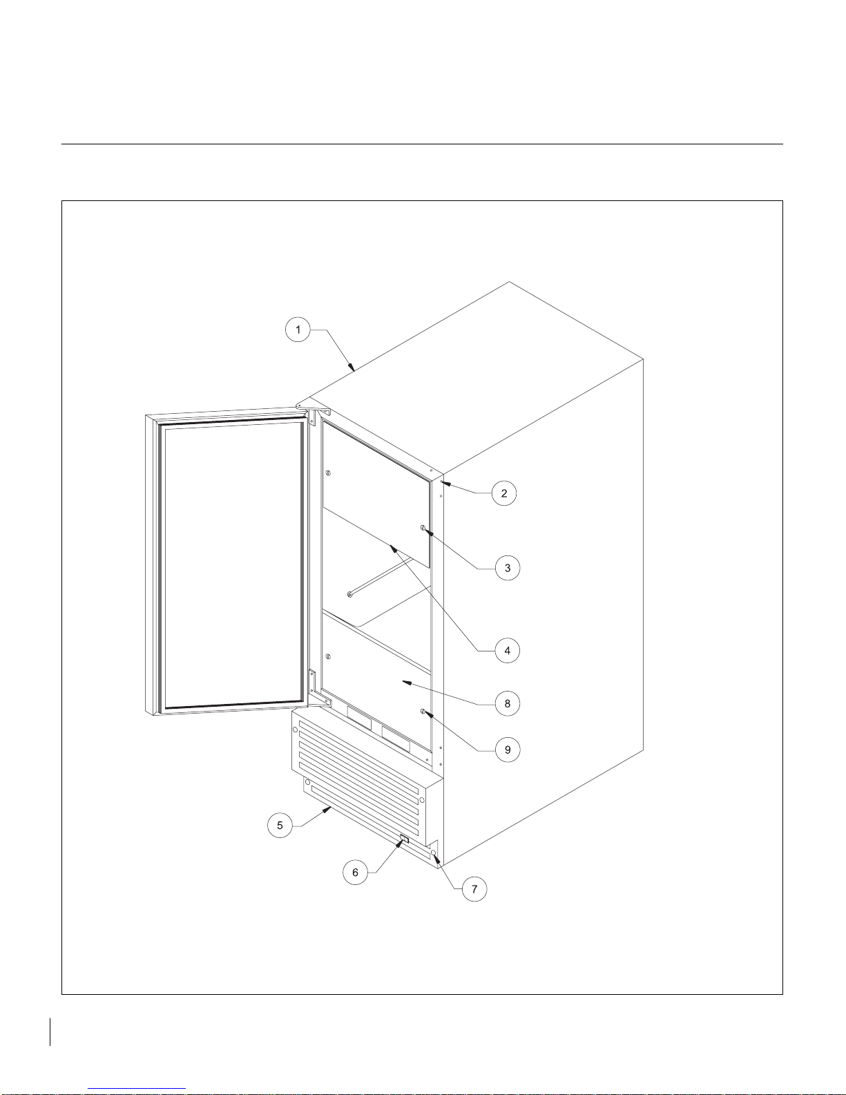
15
SERVICE PARTS DIAGRAM ONE
Page 17

Illus. No. Description Qty. Req. Part No. Service Assembly
1 Cabinet Assembly 1 V arious V arious
2 Hole Plug 6 41001929 Various
3 Screw 2 41004079 42242989
4 Escutcheon 1 41005700 42242989
5A Plastic Grille (White) 1 41006376 42243390
5B Plastic Grille (Black) 1 41006274 42243391
6 On-Off-Clean Switch 1 41005824 42242992
7A Screw (White Plastic Grille) 1 41005486 42243390
7B Screw (Black Plastic Grille) 1 08205072 42243391
8 Stainless tin panel (Optional) 1 42284093 42244709
9 Screw (Optional) 2 08204920 42244709
16
SERVICE PARTS LIST ONE
Page 18
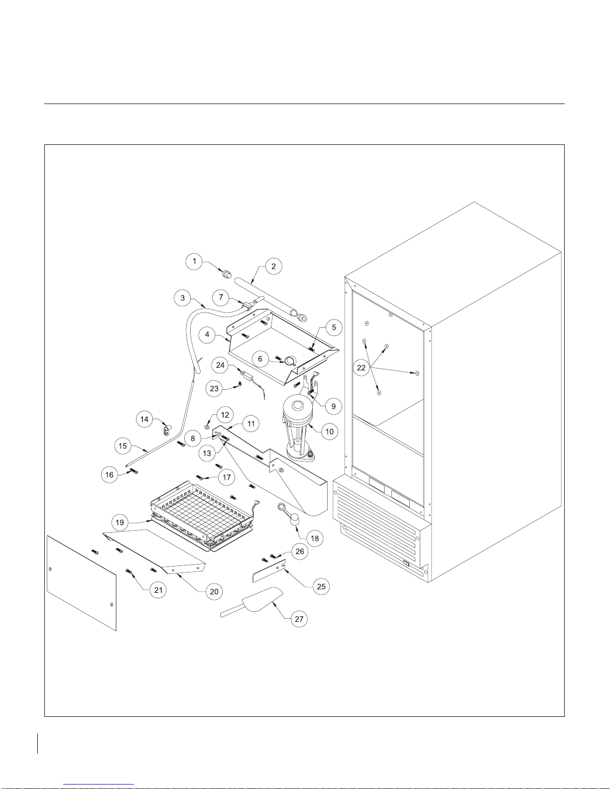
17
SERVICE PARTS DIAGRAM TWO
Page 19

Illus. No. Description Qty. Req. Part No. Service Assembly
1 Distributor Tube End 2 41005705 42242977
2 Distributor Tube 1 41005515 42242976
3 Tubing 1 41005042 42242976
4 Evaporator Assembly 1 42052559 42242978
5 Screw 4 08204920 42242978
6 Clamp 1 41006002 42242978
7 Hose Clamp 1 41006126 42242976
8 Washer 2 08205068 42242981
9 Screw 2 08204920 42242980
10 Circulation Pump 1 41005537 42242980
11 Reservoir 1 41005345 42242981
12 Spacer 2 41004366 42242981
13 Screw 2 41005773 42242981
14 Clamp 1 1150003A 42242986
15 Sleeve w/ thermistor 1 42154607 42242986
16 Screw 2 08204920 42242986
17 Screw 4 08204920 42242984
18 Drain Plug 1 41005859 42242982
19 Grid-Cutter Assembly 1 42412615 42242984
20 Deflector 1 41006040 42242985
21 Screw 4 08204920 42242985
22 Wellnut 20 41005503 42242987
23 Screw 1 41004079 42243392
24 Thermistor 1 41006205 42243392
25 Retainer Clip 1 41006042 42242975
26 Screw 2 08204920 42242975
27 Ice Scoop 1 41005536 42242993
18
SERVICE PARTS LIST TWO
Page 20
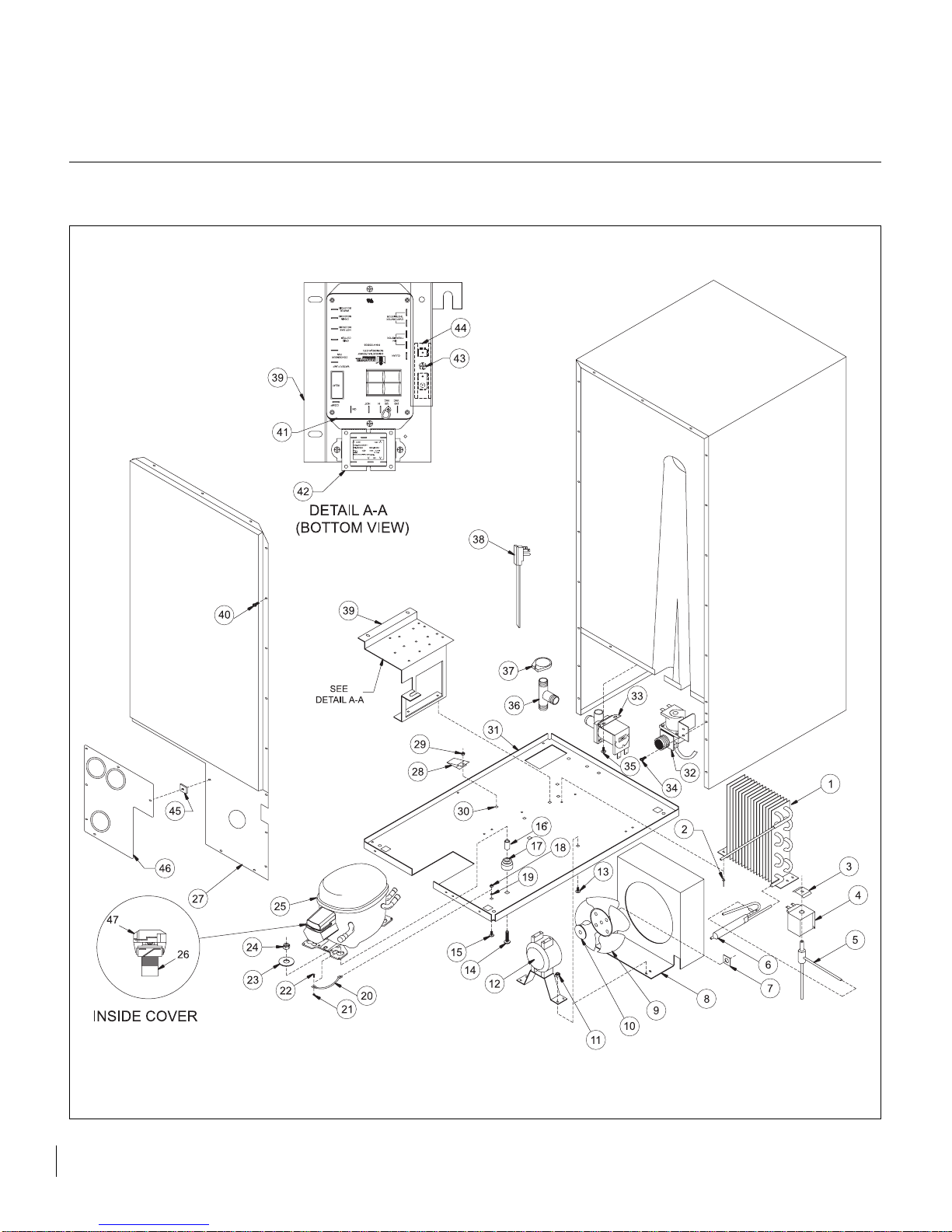
19
SERVICE PARTS DIAGRAM THREE
Page 21
Illus. No. Description Qty. Req. Part No. Service Assembly
1 Condenser 1 41003609 42243035
2 Pop Rivet, Steel 4 41003962 42243035
3 Coil Retainer 1 41003662 42242020
4 Solenoid Coil 1 41003601 42242020
5 Hot Gas Valve 1 41003914 42242020
6 Drier Assembly 1 42102389 42242961
7 Speed Nut 1 41000153 42244701
8 Fan Shroud 1 41006282 42244704
9 Fan Blade 1 41003616 42244701
10 Silencer, Spacer 1 M000101A 42244701
11 Locknut 5 41006874 42244701
12 Fan Motor Assembly 1 42183571 42244701
13 Carriage Bolt 5 1130006A 42244701
14 Carriage Bolt 2 08205114 42243194
15 Carriage Bolt 1 1130006A 42242900
16 Sleeve, Compressor 2 41008199 42243194
17 Grommet, Compressor 4 41008198 42243194
18 Locknut 1 41006874 42242900
19 Lock Washer 1 41005417 42242900
20 Ground Wire, Compressor 1 41001401 42242900
21 Lock Washer 1 08205116 42242900
22 Screw 1 08205200 42242900
23 Washer 2 08204877 42243194
24 Locknut 2 08205051 42243194
25 Compressor Assembly 1 41008182 42243194
26 Compressor PTC Starter 1 41008200 42244702
27 Back Panel 1 41009202 42242962
27 Back Panel-Stainless Steel 1 41009203 42245300
28 Power Cord Clamp 1 41006046 42242963
29 Locknut 1 41006874 42242963
30 Carriage Bolt 1 1130006A 42242963
31 Baseplate 1 41006276 42242964
32 Water Valve Assembly 1 42262644 42242965
33 Drain Valve 1 41005530 42242966
34 Screw 2 08204928 42242965
35 Screw 2 08204928 42242966
36 Tee Fitting 1 41005702 42242967
37 Hose Clamp 4 41006769 42242967
38 Power Cord 1 41006733 42242963
39 Bracket 1 41005868 42242968
40 Screw 24 08204928 42242962
40 Screw-Stainless Steel 24 41005076 42245300
41 Electronic control 1 41006035 42243384
42 Transformer 1 41005681 42242973
43 Screw 6 41005086 42242971
44 Terminal Block 1 41005078 42242971
45 U-Clip 1 41005945 42243015
46 Access panel assembly 1 41005943 42243016
46 Access panel assembly-Stainless Steel 1 41008533 42245301
47 Compressor Overload 1 41008201 42244703
20
SERVICE PARTS LIST THREE
Page 22
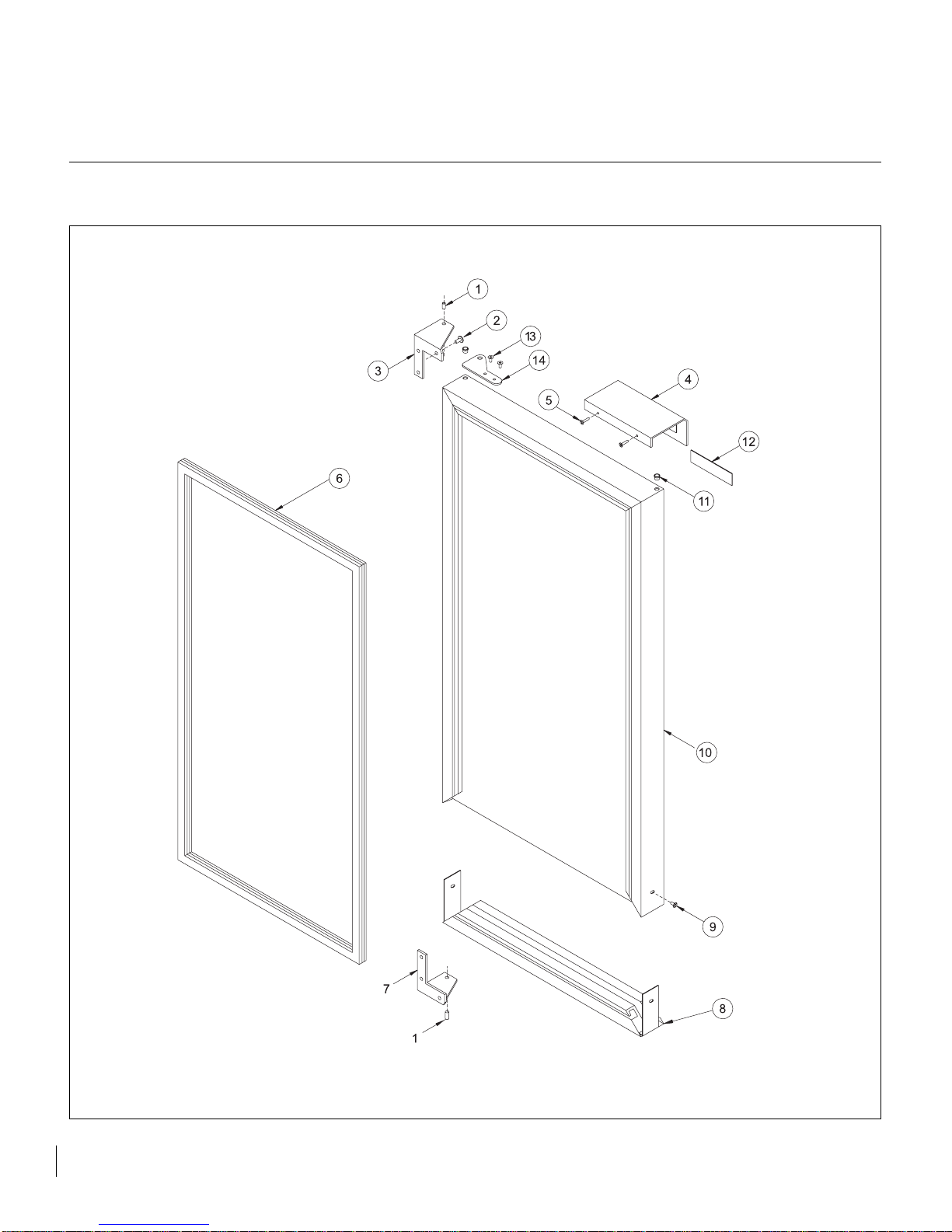
21
SERVICE PARTS DIAGRAM FOUR
Page 23

Illus. No. Description Qty. Req. Part No. Service Assembly
1 Hinge Pin 2 41004106 2240013A
2 Screw 6 Various Various
3 Hinge 1 Various Various
4 Handle 1 Optional Optional
5 Screw 2 Optional Optional
6 Door Gasket 1 41006285 42243388
7 Hinge 1 Various Various
8 RPE Cap Assembly 1 Optional Optional
9 Screw 2 Optional Optional
10 Door, Complete Assembly, 30IM 1 Various Various
11 Hinge Bushing 4 41000255 2240013A
12 Door Nameplate 1 Various Various
13 Hinge Adapter Screw 4 Optional Optional
14 Hinge Adapter 2 Optional Optional
22
SERVICE PARTS LIST FOUR
Page 24

41006412 Rev. G
WWW.MARVELINDUSTRIES.COM
Phone: (765) 962-2521 Fax: (765) 962-2493
MARVEL
INDUSTRIES
Part of AGA Foodservice Group
233 Industrial Parkway
P.O. Box 997
Richmond, IN 47375-0997
 Loading...