

Page 1
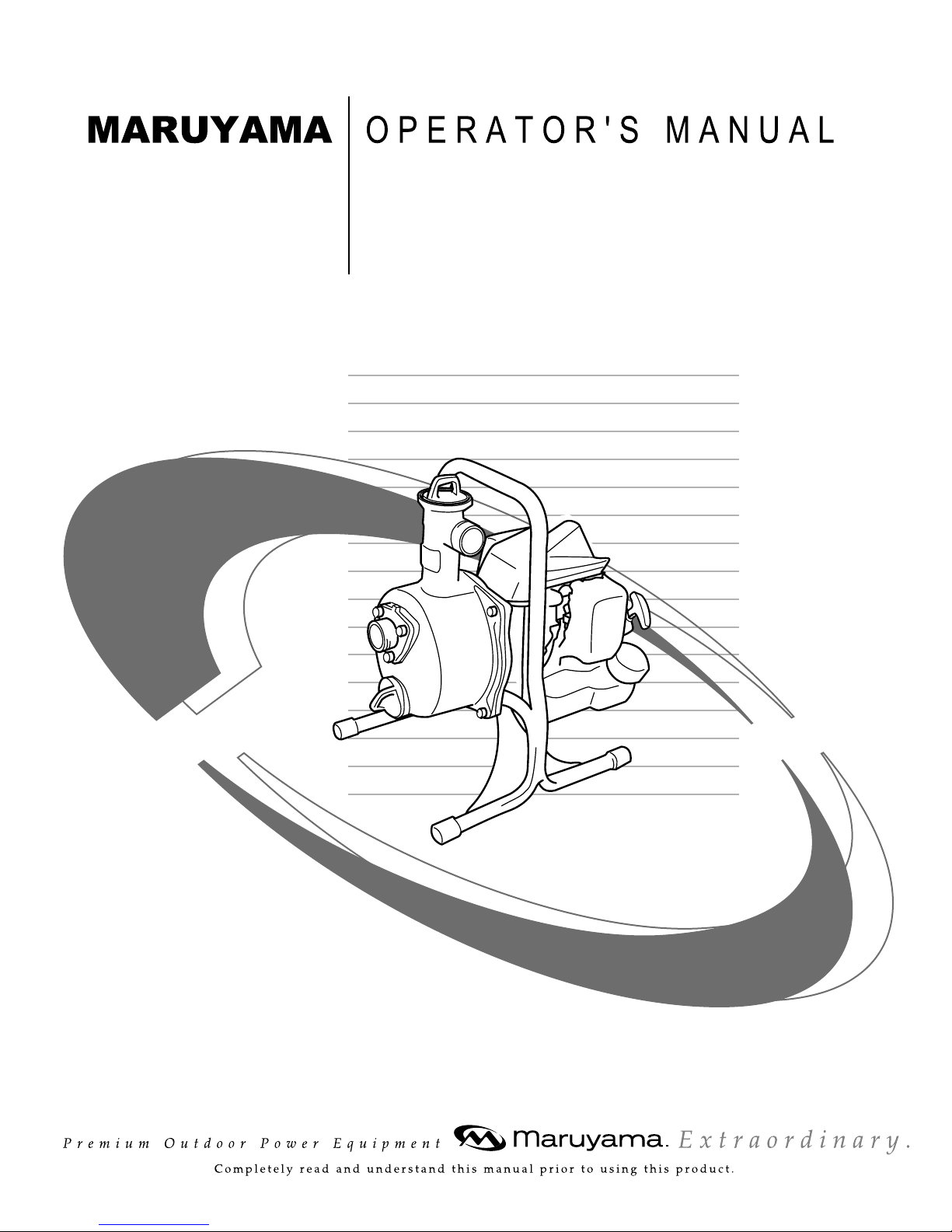
Water Pump
MP2531CE-1
MP2531CE-1CA
Page 2
— 1 —
Limited W arranty Statement
All Maruyama commercial/ industrial products are warranted to the original purchaser to be free from defects
in material and workmanship from the date of purchase for the time periods listed as follows:
Lifetime for inner drive shaft on trimmers and brushcutters and all ignition modules.
3 years for residential, non-institutional, non-income producing use.
1 year for industrial, commercial, institutional, rental and income producing use.
Maruyama AE series engines and Kawasaki TEX45/TEX54 are covered exclusively for one additional
year of industrial, commercial, institutional, rental and income producing use (total of 2 years).
All other engines refer to engine manufacturer's warranty statement.
Any part of a Maruyama product found to be defective within the applicable warranty period shall, at
Maruyama's option, be repaired or replaced without charge. Warranty consideration is obtained by delivering
any Maruyama product believed to be defective to an Authorized Maruyama Servicing Dealer within the
applicable warranty period.
The purchaser shall not be charged for diagnostic labor that leads to the determination that a warranted part
is defective, if the diagnostic work is performed at a Maruyama Dealer.
Any warranted part which is not scheduled for replacement as required maintenance, or which is scheduled
only for regular inspection to the effect of "repair or replace as necessary" shall be warranted for the warranty
period. Any warranted part, which is scheduled for replacement as, required maintenance shall be warranted
for the period of time up to the first scheduled replacement point for that part. Maruyama Mfg. Co., Inc. is
liable for damages to other engine components caused by the failure of a warranted part still under warranty.
The purchaser is responsible for the performance of the required maintenance, as defined by Maruyama Mfg.
Co., Inc. in the Owner's/Operator's Manual.
EMISSION-RELATED PARTS WARRANTY: In addition to the above warranty coverage, Maruyama Mfg.
Co., Inc. will repair or replace, free of charge, for the original purchaser and each subsequent purchaser any
emission-related part or parts found to be defective in material and workmanship for two (2) years from original retail delivery date. Emission-related parts are the carburetor assembly, the ignition coil assembly,
the ignition rotor, the spark plug, the catalytic converter and the fuel tank. Any replacement part that is
equivalent in performance and durability may be used in non-warranty maintenance or repairs, and shall not
reduce the warranty obligations of Maruyama Mfg. Co., Inc.
Page 3

— 2 —
This warranty does not cover the following:
1. Maintenance items (excluding defects in materials and workmanship) including hoses, spark plugs,
starter rope, air and fuel filters, throttle cables and all pump attachments, etc.
2. Extra expenses including shipping and handling, travel, payment for lost time or pay and for any inconvenience and storage.
3. Alterations or modifications including aftermarket parts not authorized by Maruyama U.S., Inc.
4. Wear, accident, abuse, neglect, misuse, negligence, improper fuels, lubricants, fuel mixtures (when
applicable), or failure to operate or maintain the product in accordance with instructions approved by
Maruyama.
Repair or replacement as provided under this warranty is the exclusive remedy of the consumer. Maruyama
shall not be liable for any incidental or consequential damages for breach of any express or implied warranty
on these products except to the extent prohibited by applicable law. Any implied warranty of merchantability
or fitness for a particular purpose on these products is limited in duration to the warranty period as defined in
the limited warranty statement. Maruyama reserves the rights to change or improve the design of the product
without notice and does not assume obligation to update previously manufactured products.
This warranty provides you with specific legal rights, which may vary from state to state.
It is the Owner's and Dealer's responsibility to make sure the Warranty Registration Card is properly filled out
and mailed to Maruyama U.S., Inc. Proof of purchase and registration will be required in order to obtain warranty service.
To locate an Authorized Maruyama Servicing Dealer nearest you, contact:
.
Maruyama U.S., Inc.
PO Box 2107
Denton, TX 76202 U.S.A.
Phone 940-383-7400
www.maruyama-us.com
Page 4
— 3 —
FEDERAL EMISSION CONTROL WARRANTY STATEMENT
YOUR WARRANTY RIGHTS AND OBLIGATIONS
The U.S. Environmental Protection Agency (EPA), and Maruyama Manufacturing Company, Inc.
are pleased to explain the emission control system warranty on your small off-road engine. New
1997 and later model year small off-road engines must be designed, b uilt and equipped, at the time
of sale, to meet the U.S. EP A regulations for small off-road engines. The equipment engine must be
free from defects in materials and workmanship which cause it to f ail to conf orm with U .S . EPA standards for the first two y ears of engine use from the date of sale to the ultimate purchaser. Maruyama
Manufacturing Company, Inc. must warrant the emission control system on your small off-road
engine for the period of time listed above provided there has been no abuse, neglect or improper
maintenance of your small off-road engine.
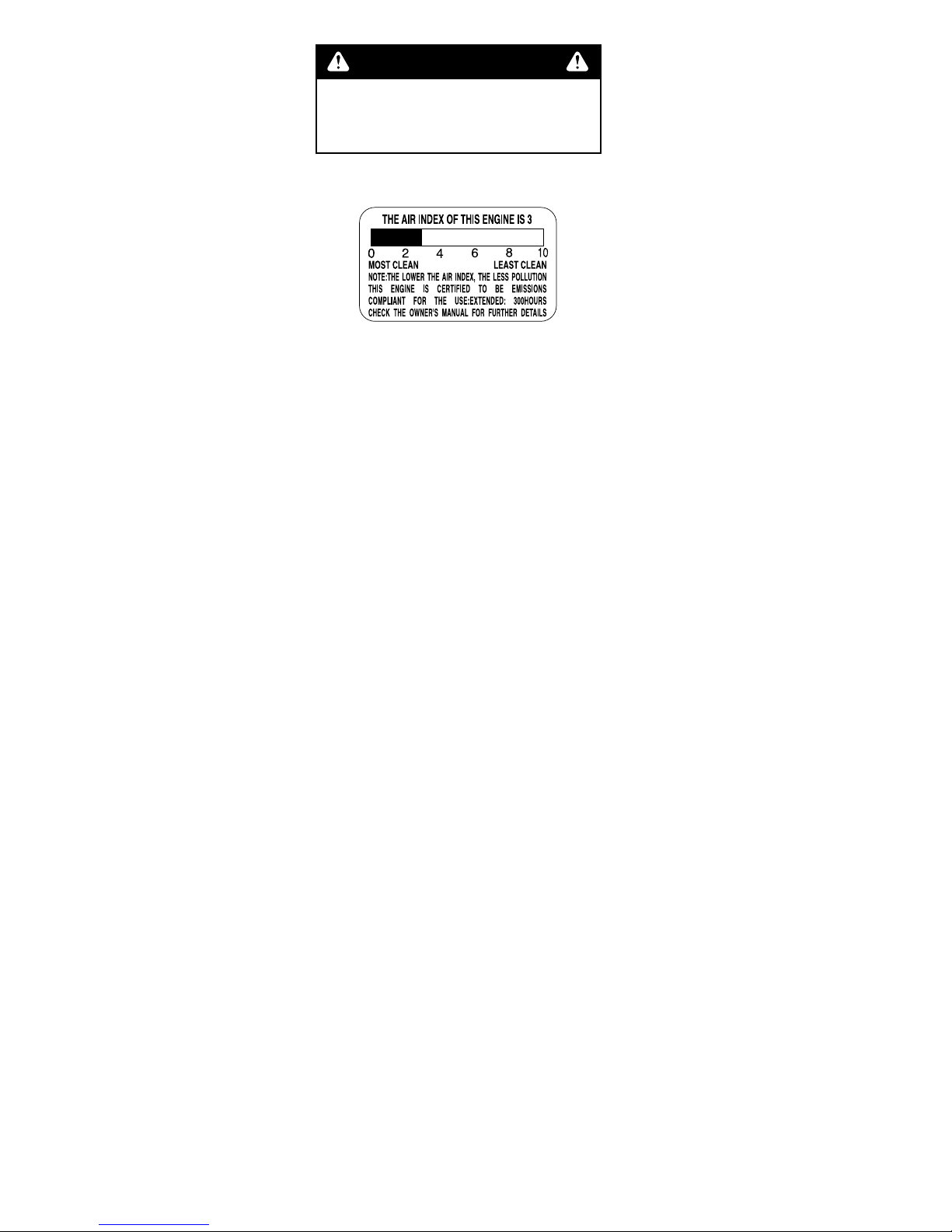
Emission durability of 300 hours.
Your emission control system may include parts such as the carburetor or fuel injection system, the
ignition system, and catalytic converter. Also included may be hoses, belts, and connectors and
other emission related assemblies.
Where a warrantable condition exists, Maruyama Manufacturing Company, Inc. will repair your
small off-road engine at no cost to you, including diagnosis (if the diagnostic work is perfor med at
an authorized dealer), parts, and labor.
MANUFACTURER'S WARRANTY COVERAGE:
The 1997 and later model year small off-road engines are warranted for two years. If any emission-related part on your engine is defective, the part will be repaired or replaced by Maruyama
Manufacturing Company, Inc. free of charge.
OWNER'S WARRANTY RESPONSIBILITIES:
(a) As the small off-road engine owner, you are responsible for the performance of the required
maintenance listed in your owner's manual.
Maruyama Manufacturing Company, Inc. recommends that you retain all receipts covering
maintenance on your small off-road engine, but Maruyama Manufactur ing Company, Inc.
cannot deny warranty solely for the lack of receipts or for your failure to ensure the performance of all scheduled maintenance. Any replacement part or service that is equivalent in
performance and durability may be used in non-warranty maintenance or repairs, and shall
not reduce the warranty obligations of the engine man ufacturer.
The engine exhaust from this product
contains chemicals known to the State
of California to cause cancer, birth
defects or other reproductive harm.
WARNING
:
.
.
MP2531CE-1
MP2531CE-1CA
Page 5

— 4 —
(b) As the small off-road engine owner, you should be aware, however, that Maruyama
Manufacturing Company may deny you warranty coverage if your small off-road engine or a
part has failed due to abuse, neglect, improper maintenance or unapproved modifications.
(c) You are responsible for presenting your small off-road engine to a Maruyama Manufacturing
Company, Inc. service center as soon as a problem exists. The warranty repairs should be
completed in a reasonable amount of time, not to exceed 30 days.
If you have any questions regarding your warranty rights and responsibilities, you should contact
Maruyama U.S ., Inc. at 1-866-783-7400.
COVERAGE
Maruyama Manufacturing Company, Inc. warrants to the ultimate purchaser and each subsequent purchaser that your small off-road engine will be designed, built and equipped, at the time
of sale, to meet all applicable regulations . Maruyama Manufacturing Company , Inc. also warr ants
to the initial purchaser and each subsequent purchaser that your small off-road engine is free
from defects in materials and workmanship which cause the engine to f ail to conf orm with applicable regulations for a period of two y ears .
The 1997 and later model years, EPA requires manufacturers to small off-road engines for two
years. These warranty periods will begin on the date the small off-road engine is purchased by
the initial purchaser. If any emission-related part on your engine is defective, the par t will be
replaced by Maruyama Manuf acturing Company, Inc. at no cost to the owner.
Maruyama Manufacturing Company, Inc. shall remedy warranty defects at any authorized
Maruyama Manufacturing Company, Inc. engine dealer or warranty station. Any authorized work
done at an authorized dealer or warranty station shall be free of charge to the o wner if such w ork
determines that a warranted part is defective. An y manufacturer-approved or equivalent replacement part may be used for any warranty maintenance or repairs on emission-related parts, and
must be provided free of charge to the owner if the part is still under warranty, Maruyama
Manufacturing Company, Inc. is liable for damages to other engine components caused by the
failure of a warranted part still under warranty.
EPA considers emission-related warranted parts to include all the parts listed below. These warranted parts are: the carburetor assembly, the ignition coil assembly, the ignition rotor, the
spark plug, the catalytic con verter, and the fuel tank.
MAINTENANCE REQUIREMENTS
The owner is responsible for the performance of the required maintenance as defined by the
Maruyama Manufacturing Company, Inc. in the owner's manual.
LIMITATIONS
This Emission Control System Warranty shall not cover any of the following:
(a) repair or replacement required because of misuse or neglect, lack of required maintenance,
repairs improperly performed or replacements not conforming to Maruyama Manufacturing
Company, Inc. specifications that adversely affect perfor mance and/or durability, and alterations or modifications not recommended or approved in writing b y Maruyama Manuf acturing
Company, Inc., and
(b) replacement of parts and other ser vices and adjustments necessary for required mainte-
nance at and after the first scheduled replacement point.
Page 6

— 5 —
CALIFORNIA EMISSION CONTROL WARRANTY STATEMENT
YOUR WARRANTY RIGHTS AND OBLIGATIONS
The California Air Resources Board (CARB), and Maruyama Manufacturing Company, Inc. are
pleased to explain the emission control system warranty on your 2010 small off-road engine. In
California, new small off-road engines must be designed, built and equipped to meet the State's
stringent anti-smog standards. Maruyama Manufacturing Company, Inc. must warrant the emission
control system on your small off-road engine for the period of time listed above provided there has
been no abuse, neglect or improper maintenance of y our small off-road engine .
Your emission control system may include parts such as the carburetor or fuel injection system, the
ignition system, and catalytic converter. Also included may be hoses, belts, and connectors and
other emission related assemblies.
Where a warrantable condition exists, Maruyama Manufacturing Company, Inc. will repair your
small off-road engine at no cost to you, including diagnosis, parts, and labor.
MANUFACTURER'S WARRANTY COVERAGE:
The 1995 and later small off-road engines are warranted for two years. If any emission-related part
on your engine is defective, the par t will be repaired or replaced by Maruyama Manufacturing
Company, Inc.
OWNER'S WARRANTY RESPONSIBILITIES:
(a) As the small off-road engine owner, you are responsible for the performance of the required
maintenance listed in your owner's manual.
Maruyama Manufacturing Company, Inc. recommends that you retain all receipts covering
maintenance on your small off-road engine, but Maruyama Manufactur ing Company, Inc.
cannot deny warranty solely for the lack of receipts or for your failure to ensure the performance of all scheduled maintenance
(b) As the small off-road engine owner, you should be aware, however, that Maruyama
Manufacturing Company may deny you warranty coverage if your small off-road engine or a
part has failed due to abuse, neglect, improper maintenance or unapproved modifications.
(c) You are responsible for presenting your small off-road engine to a Maruyama Manufacturing
Company, Inc. distribution center as soon as a problem exists. The warranty repairs should
be completed in a reasonable amount of time, not to exceed 30 days.
If you have any questions regarding your warranty rights and responsibilities, you should contact
Maruyama U.S ., Inc. at 1-866-783-7400.
Emission System Parts
Exhaust Emission
Carburetor
Muffler
Catalytic Converter
Ignition Coil / Magneto
Spark Plug
Air Filter
EGR V alve (piston)
Fuel Filter
Evaporative Emission
Fuel Tank
Page 7

— 6 —
Contents
Page
1. Limited Warranty Statement
........................................................
1
2. Federal Emission Control
............................................................
3
3. California Emission Control
........................................................
5
4. Introduction
..................................................................................
7
5. Specifications
...............................................................................
8
6. Product Description
.....................................................................
8
7. Standard Accessories
...................................................................
9
8. Safety
.........................................................................................
10
9. Assembly Instructions
................................................................
12
10. Before Operation
......................................................................
13
11. Operating The Water Pump
.....................................................
17
12. Carburetor Adjustment
............................................................
19
13. Maintenance
.............................................................................
20
14. Storage
.....................................................................................
23
15. Troubleshooting
.......................................................................
25
16. Maintenance Period
.................................................................
26
Page 8

— 7 —
Thank you for purchasing a Maruyama product.
Maruyama, it’s distributors, and dealers want you to be
completely satisfied with your new product. Please feel
free to contact your local Authorized Service Dealer for
help with service, genuine Maruyama parts, or other
information you may require.
Whenever you contact your Authorized Service Dealer
or the factory, always know the serial number of your
product. This number will help the Service Dealer or
Service Representative provide exact information about
your specific product. You will find the model and serial number located in a unique place on the product
(Product Description on page 9).
For your convenience, write the product model name
and serial number in the space below.
Read this manual carefully to learn how to operate and
maintain your product correctly. Reading this manual
will help you and others avoid personal injury and damage to the product.
Although Maruyama designs, produces and markets
safe, state-of-the-art products, you are responsible for
using the product properly and safely. You are also
responsible for training persons who you allow to use
the product about safe operation.
Model Name
Serial No.
Introduction
Page 9
— 8 —
Specifications
Models
Length x Width x Height
Dry Weight
Inlet/Outlet Dia
Connection Thread
Maximum Outlet Flow
Maximum Head
Displacement
Fuel Tank Capactiy
Carburetor
Ignition System
Spark Plug:
Spark Plug Gap
Gas to Oil Ratio
CARB Approved
MP2531CE-1, MP2531CE-1CA
304 x 251 x 336mm (12.0 x 9.9 x 13.2 in.)
5.5 kg (12 lbs.)
25 mm (1 in.)
PF 1
113 r/min (30 gal/min)
36 m (118 ft.)
30.1 cc
0.6r (0.63 qts.)
Walbro Diaphragm Type
Solid State
NGK BPM8Y
0.6 〜 0.7 mm (0.024 〜0.028 in.)
50:1
Tier 3
Emission durability of 300 hours.
Pump
Engine
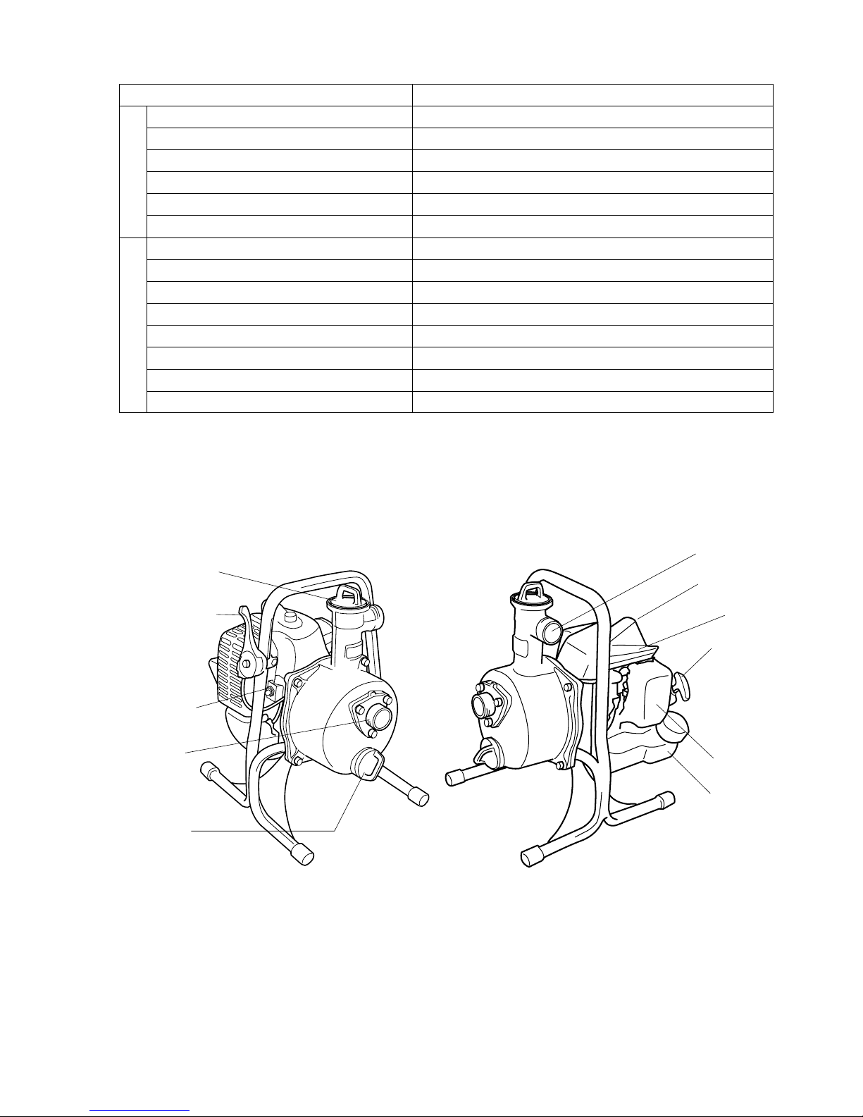
Product Description
CAP FOR PRIMING
THROTTLE LEVER
STOP SWITCH
INLET PORT
DRAIN PLUG
SPARK PLUG
ENGINE
STARTER GRIP
AIR FILTER
OUTLET PORT
FUEL TANK
Page 10
— 9 —
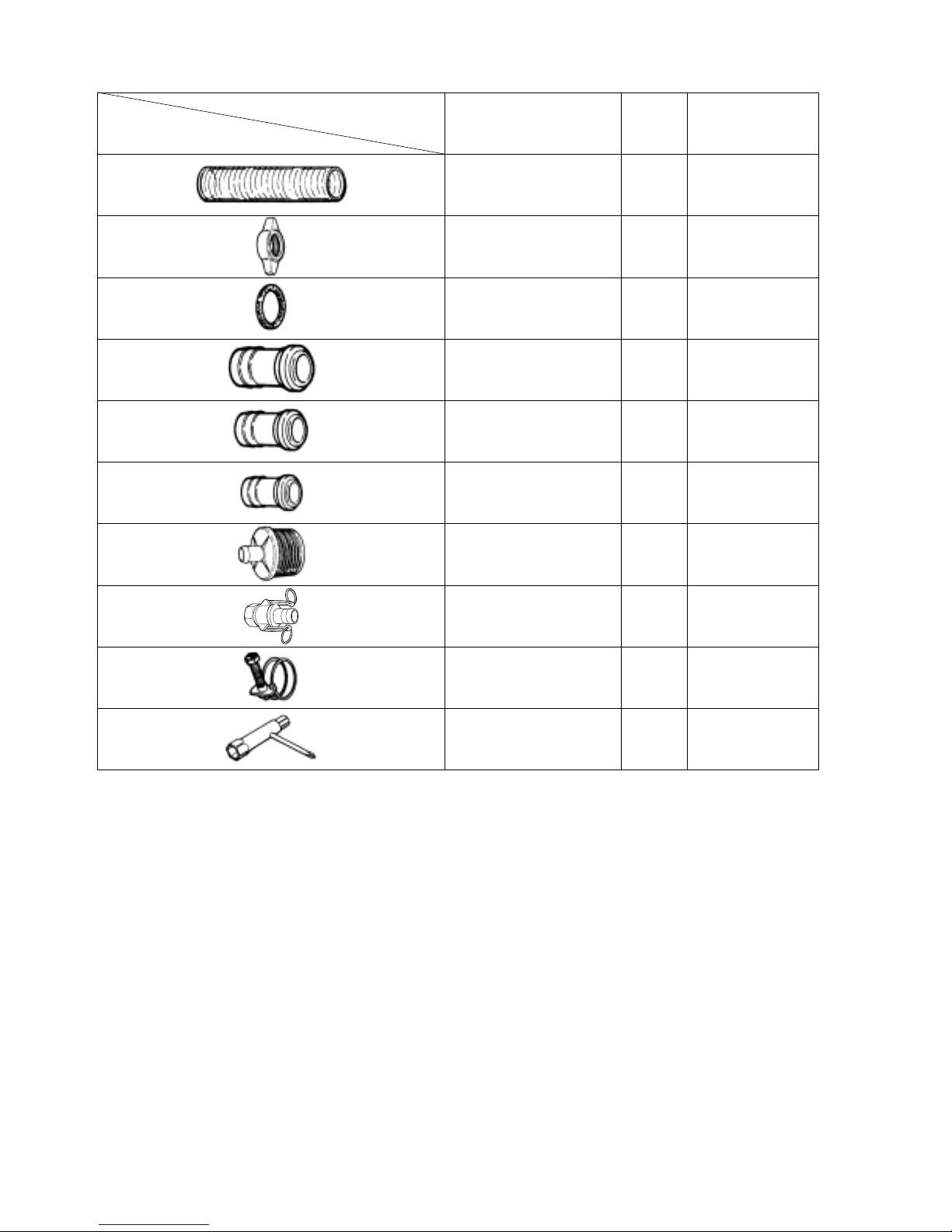
Standard Accessories
Part Name
Suction Hose
Nut
Packing
Coupling
Coupling
Coupling
Strainer
One Touch Coupler
Clamp
Box Spanner
Q'ty
1
2
2
2
1
1
1
2
3
1
3 m
1 in.
1 in.
1 in.
3/4 in.
5/8 in.
1 in
13 x 19 x +
Remarks
Page 11
— 10 —
The Maruyama warning system in this manual identifies potential hazards and has special safety messages
that help you and others avoid personal injury, even
death. DANGER, WARNING and CAUTION are signal words used to identify the level of hazard.
However, regardless of the hazard, be extremely careful.
DANGER signals an extreme hazard that will cause
serious injury or death if the recommended precautions
are not followed.
WARNING signals a hazard that may cause serious
injury or death if the recommended precautions are not
followed.
CAUTION signals a hazard that may cause minor or
moderate injury if the recommended precautions are
not followed. Two other words are also used to highlight information. “Important” calls attention to special
mechanical information and “Note” emphasizes general
information worthy of special attention.
Safety
Operator Safety
1. Read and understand this Operator’s Manual
before using this product. Be thoroughly familiar
with the proper use of this product.
2. Never allow children to operate the Water Pump.
It is not a toy. Never allow adults to operate the
unit without first reading the Operator’s Manual.
3. Never operate this Water Pump when you are
tired, ill, or under the influence of alcohol, drugs
or medication.
4. Never start or run the engine inside a closed room
or building. Breathing exhaust fumes can cause
death.
Fuel safety
1. Gasoline is highly
flammable and must
be handled and stored
carefully. Use a container approved for
fuel to store gasoline
and/or fuel/oil mixture.
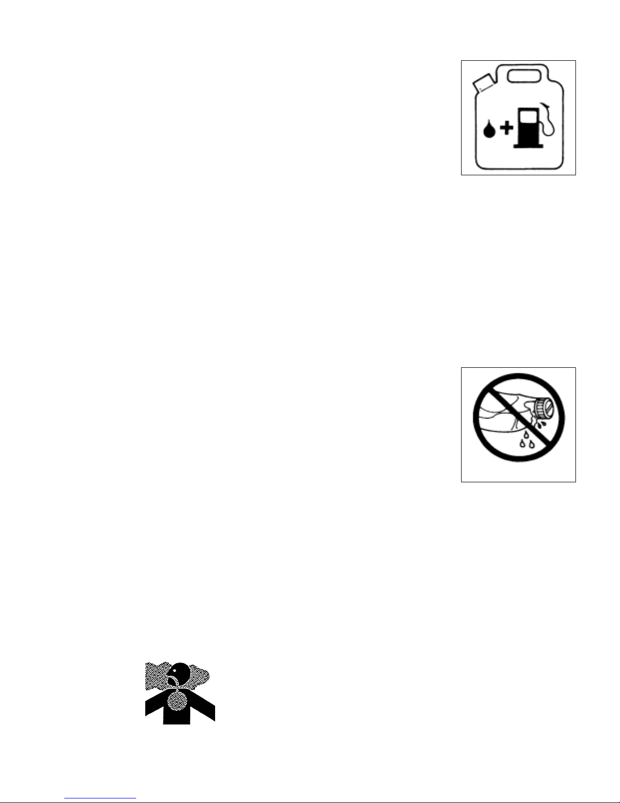
2. Mix and pour fuel outdoors, where there are no
sparks or flames.
3. Do not smoke near fuel or the water pump, or
while using the water pump.
4. Do not overfill the fuel tank. Stop filling 1/4-1/2
inch (6mm-13mm) from the top of the tank.
5. Wipe up any spilled fuel before starting the engine.
WIPE UP ANY FUEL SPILLAGE
Page 12
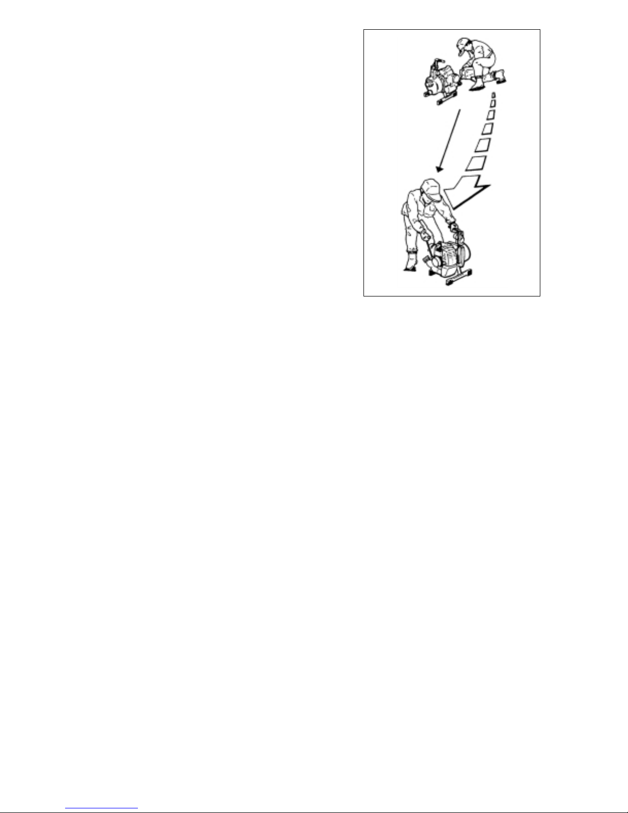
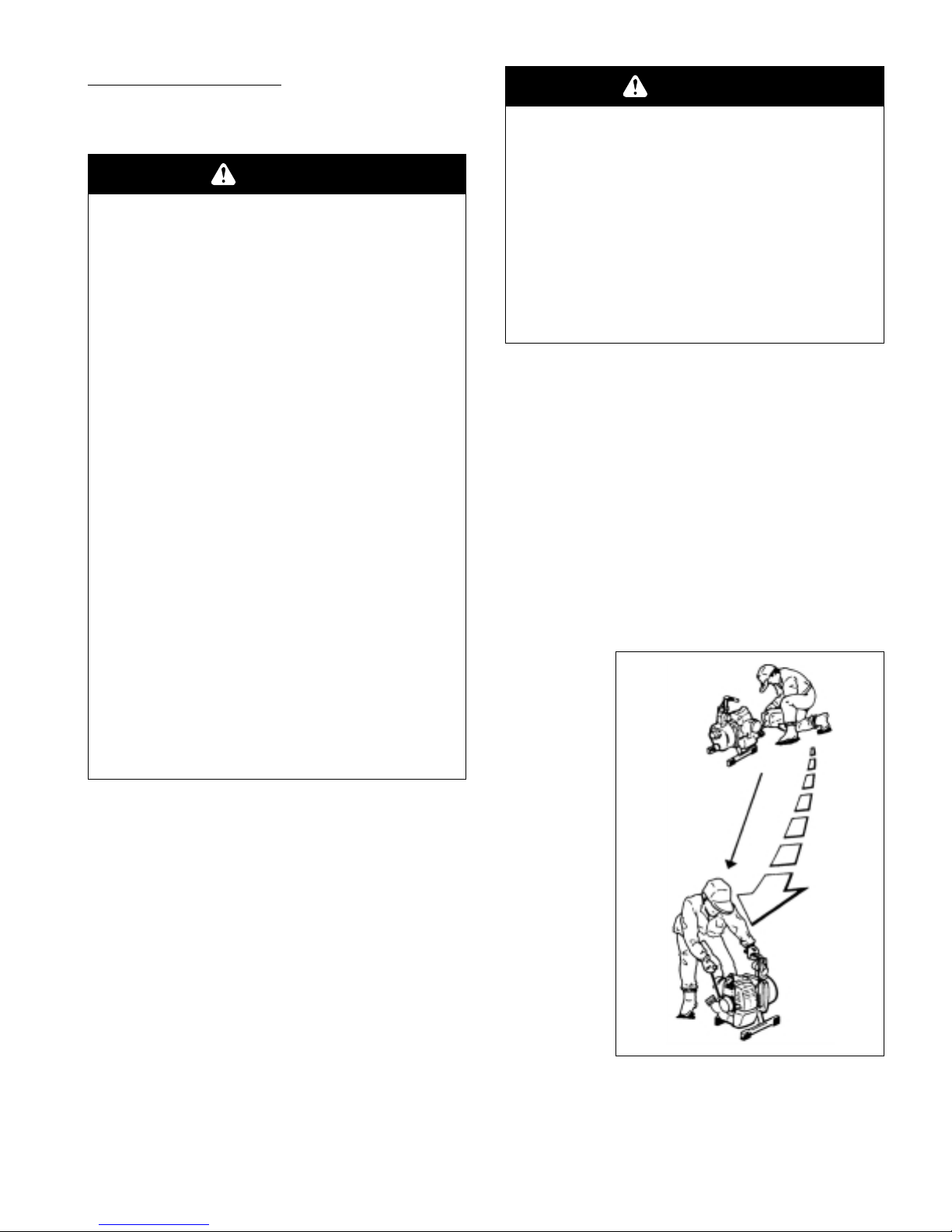
6. Move the water pump at least 10 feet (3m) away from the
fueling location before starting engine.
7. Do not remove the water pump fuel tank cap while the
engine is running or right after stopping the engine.
8. Allow the engine the cool before refueling.
9. Empty the fuel tank before storing the water pump. Fuel
should be emptied after each use. Fuel left in the tank during storage may leak.
10. Store fuel and water pump away from open flame, sparks
and excessive heat. Make sure fuel vapors cannot reach
sparks or open flames from water heaters, furnaces, electric motors, etc.
— 11 —
Min
10 feet
(3m)
Page 13
— 12 —
Assembly Instructions
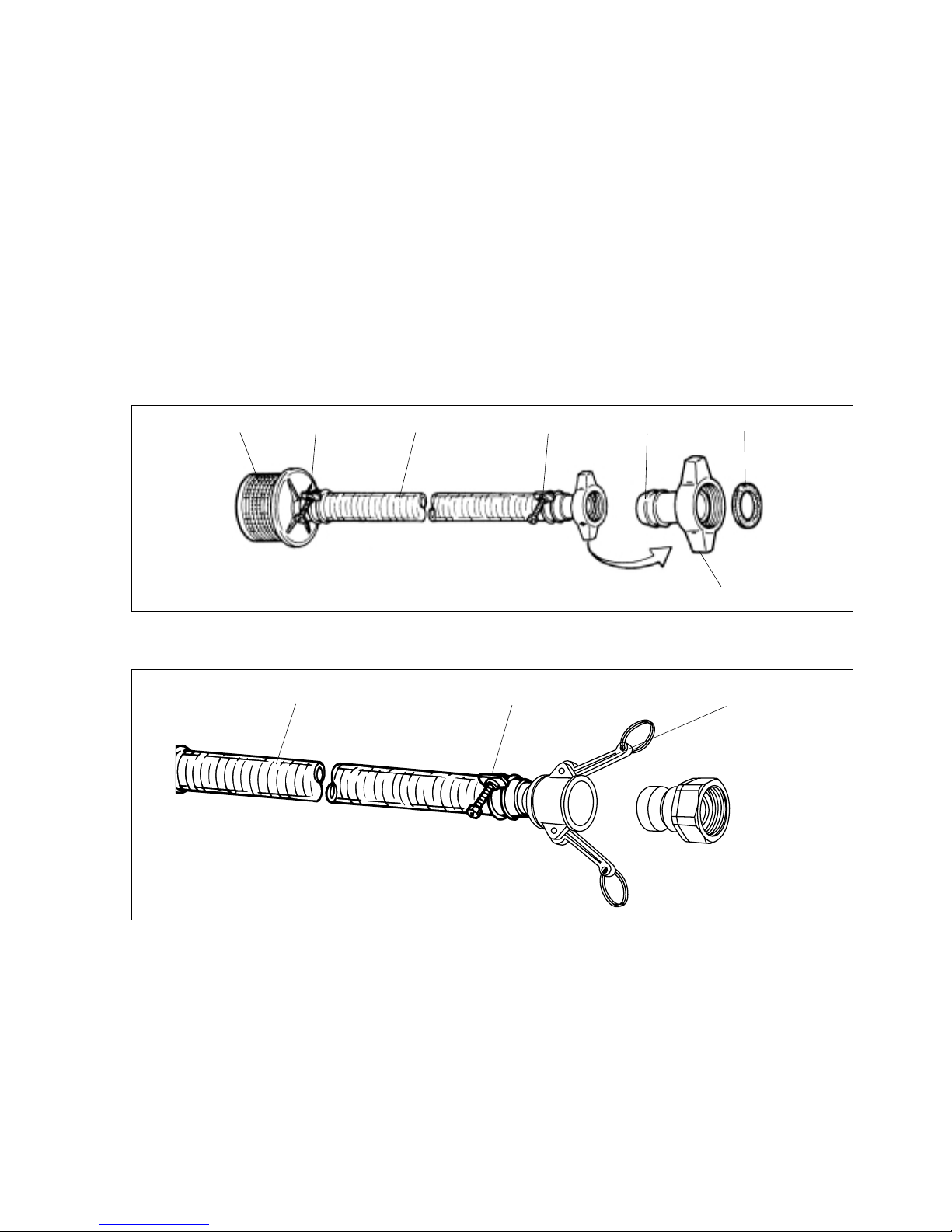
1. Install a rubber packing onto one of the 1 inch hose fittings. Slide a hose fitting nut over the fitting. Slide
two hose clamps over the suction hose. Attach the hose coupler assembly and strainer to either end and
tighten the hose clamps.
Due to different operator requirements, the discharge hose is not provided. Three hose fittings and the
one touch coupler are supplied with water pump to be used with either 5/8, 3/4 or 1 inch inside diameter
hose. Select an discharge hose that is the suitable diameter and length for your application.
Once you have selected the outlet hose, assemble the appropriate hose f itting, packing and not and secure
the fitting to the hose with the hose clamp.
STRAINER
CLAMP
SUCTION HOSE
CLAMP
COUPLING
PACKING
NUT
Suction Hose Assembly (1 inch Hose Fitting)
Discharge Hose Assembly (One Touch Coupler)
DISCHARGE HOSE CLAMP ONE TOUCH COUPLER
Page 14
— 13 —
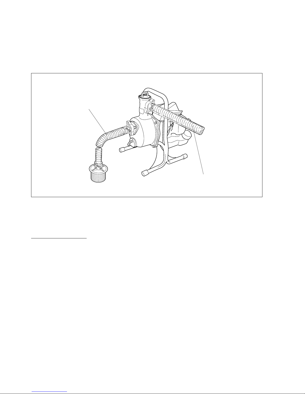
2. Fix the suction hose and the outlet hose to the pump, as shown.
WARNING: Always use the suction hose and strainer provided among the standard accessories. If another
suction hose is used, it must be used with the strainer.
A crush resistant hose is recommended.
※
During operation, if the suction hose is crushed, it can cause the pump to fail.
Before Operation
PUMP SECTION
1. Check that there are no loose screws or components on the machinery.
2. Place the pump on a level surface, but not immediately next to the w ater supply.
If the pump must be placed on a sloping or inclined surface, a level platform must be used. Be sure to
secure the pump adequately .
3. Where the weight of the suction hose causes the pump to tilt or move, secure the pump adequately.
4. Always attach the strainer to the end of the suction hose. If the pump is operated without the strainer,
pebbles and other materials will be sucked into the pump and could cause damage and pump failure.
5. Be sure that the strainer is completely submerged, but not in contact with sandy or muddy bottom surfaces.
6. Secure the suction and outlet hoses tightly to the pump to avoid sucking air .
SUCTION HOSE
DISCHARGE HOSE
Page 15
— 14 —
ENGINE SECTION
Oil and Fuel
1. Do not smoke near fuel.
2. Mix and pour fuel outdoors and where there are
no sparks or flames.
3. Always shut off the engine before refueling.
Never remov e the fuel tank cap while the engine is
running or just right after sopping the engine.
4. Always open the fuel tank cap slowly to release
any possible overpressure inside the tank.
5. Do not overfill the fuel tank. Stop filling 1/4-1/2
inch (6 mm-13 mm) from the top of the tank.
6. Tighten the fuel tank cap carefully but firmly after
refilling.
7. Wipe up any spilled fuel before starting the
engine.
8. Move the Water Pump at least 10 feet (3 m) away
from the fueling location and fuel storage container before starting the engine.
DANGER
POTENTIAL HAZARD
• In certain conditions gasoline is extremely flammable and highly explosive.
WHAT CAN HAPPEN
• A fire or explosion from gasoline can
burn you, others, and cause proper ty
damage.
HOW TO AVOID THE HAZARD
• Use a funnel and fill the fuel tank outdoors, in an open area, when the engine
is cold. Wipe up any gasoline that spills.
• Do not fill the fuel tank completely full.
Add gasoline to the fuel tank until the
level is 1/4” to 1/2” (6 mm to 13 mm)
below the bottom of the filler neck. This
empty space in the tank allows gasoline
to expand.
• Never smoke when handling gasoline,
and stay away from an open flame or
where gasoline fumes may be ignited by
a spark.
• Store gasoline in an appr oved container
and keep it out of the reach of children.
• Never buy more than a 30-day supply of
gasoline.
WARNING
POTENTIAL HAZARD
• Gasoline contains gasses that can build
up pressure inside a gas tank.
WHAT CAN HAPPEN
• Fuel can be sprayed on you when
removing gas cap.
HOW TO AVOID THE HAZARD
• Remove fuel cap slowly to avoid injur y
from fuel spray.
Min
10 feet
(3m)
Page 16
— 15 —
Recommended Oil T ype
Only use a two-cycle engine oil formulated for use in
high-performance, air-cooled two-cycle engines.
Maruyama brand 2-cycle oil is formulated for use in
high-performance, air-cooled two-cycle engines.
IMPORTANT: Do not use National Marine
Manufacturer’s Association (NMMA) or BIA
certified oils. This type of 2-cycle engine oil
does not have the proper additives for aircooled, 2-cycle engines and can cause engine
damage.
Do not use automotive motor oil. This type of
oil does not have the proper additives for aircooled, 2-cycle engines and can cause engine
damage.
Recommended Fuel T ype
Use clean, fresh lead-free gasoline, including oxygenated or reformulated gasoline, with an octane rating of 89
or higher. To ensure freshness, purchase only the quantity of gasoline that can be used in 30 days. Use of
lead-free gasoline results in fewer combustion chamber
deposits and longer spark plug life. Use of premium
grade fuel is not necessary or recommended.
Use of Fuel Additives
IMPORTANT: NEVER USE METHANOL,
GASOLINE CONTAINING METHANOL
,
GASOHOL CONTAINING MORE THAN
10% ETHANOL, PREMIUM GASOLINE, OR
WHITE GAS BECAUSE ENGINE FUEL SYSTEM DAMAGE COULD RESULT.
DO NOT USE FUEL ADDITIVES OTHER
THAN THOSE MANUFACTURED FOR
FUEL STABILIZATION DURING STORAGE
SUCH AS MARUYAMA’S STABILIZER/
CONDITIONER OR A SIMILAR PRODUCT.
MARUYAMA’S STABILIZER/CONDITIONER IS A PETROLEUM DISTILLATE BASED
CONDITIONER/STABILIZER.
MARUYAMA DOES NOT RECOMMEND
STABILIZERS WITH AN ALCOHOL BASE
SUCH AS ETHANOL, METHANOL OR ISOPROPYL. ADDITIVES SHOULD NOT BE
USED TO TRY TO ENHANCE THE POWER
OR PERFORMANCE OF MACHINE.
Mixing Gasoline And Oil
IMPORTANT: The engine used on this Water
Pump is of a 2-cycle design. The internal moving parts of the engine, i.e., crankshaft bearings,
piston pin bearings and piston to cylinder wall
contact surfaces, require oil mixed with the
gasoline for lubrication.
Failure to add oil to the gasoline or failure to
mix oil with the gasoline at the appropriate
ratio will cause major engine damage which will
void your warranty.
For your fuel premix, use Maruyama Premium
2-cycle Oil Mix, or equivalent ISO-L-EGD &
JASO FC oil with a minimum 89 octane high
quality gasoline. Maruyama 2-cycle oil is specially formulated to meet the requirements of
high-performance, low-emission air-cooled 2cycle engines. Use of other oils may lead to service issues which may not be covered by your
warranty.
Fuel Mixture
The fuel: oil ratio is 50 parts gasoline to 1 part oil or
50:1.
50:1
Page 17
— 16 —
Note: Never use a mixing ratio less than 50:1 regardless of the oil package mixing instruc-
tions. Ratios less the 50:1, (for example, 60:1, 80:1, 100:1), reduce the amount of
lubrication to the internal moving parts of the engine and can cause damage.
Mixing Instructions
IMPORTANT: Never mix gasoline and oil directly in the Water Pump fuel tank.
1. Always mix fuel and oil in a clean container approved for gasoline.
2. Mark the container to identify it as fuel mix for the Water Pump.
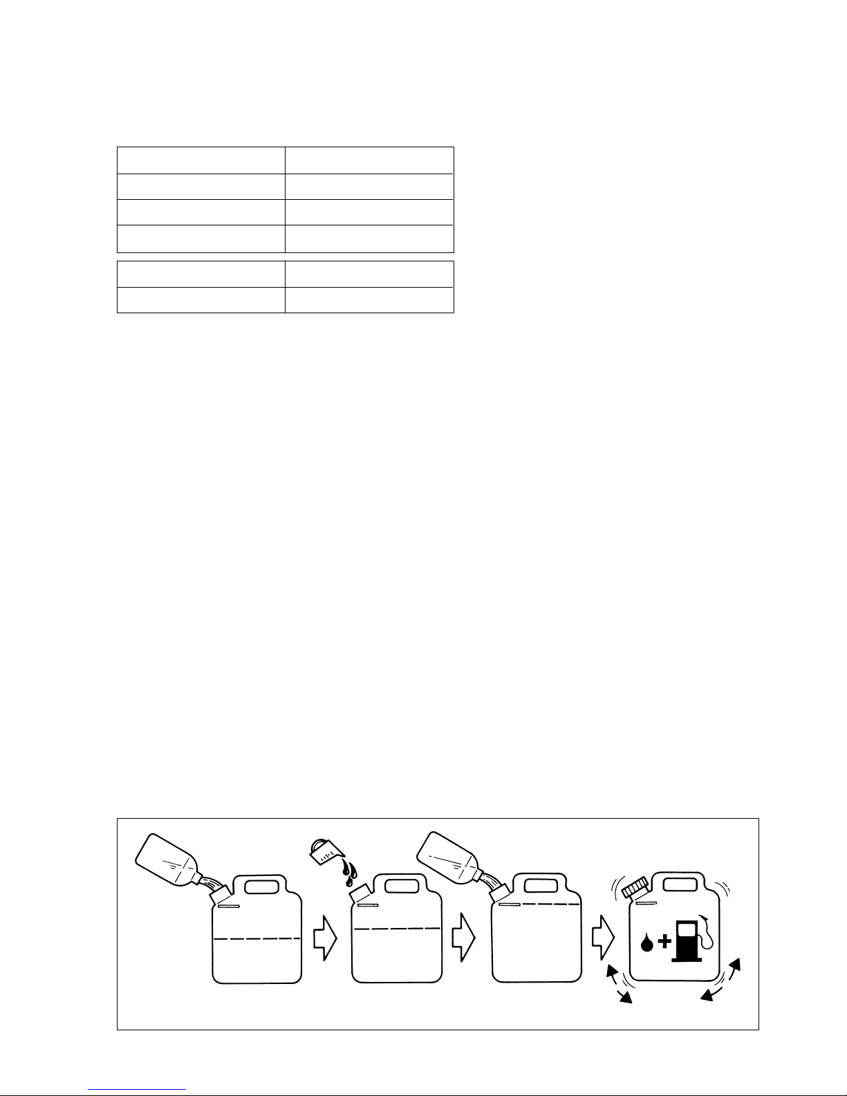
3. Use regular unleaded gasoline and fill the container with half the required amount of gasoline.
4. Pour the correct amount of oil into the container then add the remaining amount of gasoline.
5. Close the container tightly and shake it momentarily to evenly mix the oil and the gasoline before filling the fuel tank on the Water Pump.
6. When refilling the Water Pump fuel tank, c lean around the fuel tank cap to prevent dirt and debris
from entering the tank during cap removal.
7. Always shake the premix fuel container momentarily before filling the fuel tank.
8. Always use a spout or funnel when fueling to reduce fuel spillage.
9. Fill the tank only to within 1/4-1/2 inch (6 mm-13 mm) from the top of the tank. Avoid filling to the
top of the tank filler neck.
Gasoline 50:1 2-cycle oil
1 gallon 2.6 oz.
2 gallons 5.1 oz.
5 gallons 12.8 oz.
1 litre 20 ml
5 litre 100 ml
Fuel Mixture Chart
GAS GAS CLOSE TIGHTLY
FILL MARK
HALF GASOLINE ADD OIL ADD REMAINING
GASOLINE
SHAKE
(MIX OIL AND GASOLINE)
OIL
Page 18
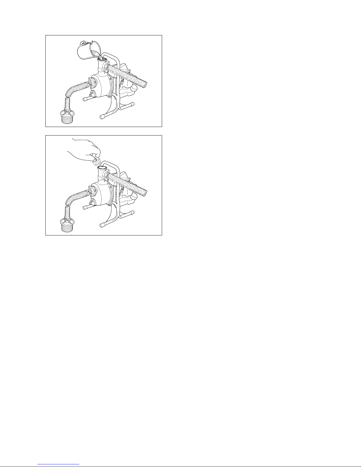
— 17 —
1. Remove the water inlet cap
Fill the pump casing with priming water until it is full.
Shake the equipment slightly so that trapped air is easily
removed.
2. Fasten the cap tightly.
WARNING: (1) Never start the engine without first priming the pump. If the engine is started without
first priming the pump with water , the w ater pump mechanical seal will be permanently damaged.
WARNING: (2) Before running the engine, be sure to immerse the suction hose in the water. Running
the engine with only priming water will cause the temperature of the priming water to
rise, damaging the mechanical seal.
3. After the engine starts, the pump will gradually start suction. Once suction starts, let the pump run 2-3
minutes to warm up, and then operate it at the specified rpm setting.
4. To stop water pump operation, press the engine stop b utton.
5. When the engine is restarted, the pump will operate without priming, but the level of the water inside the
casing must be checked before starting in the event that the suction hose end is exposed, the installation
site is changed, or the pump has not been used for a long time.
Operating The Water Pump
Page 19
— 18 —
Starting And Stopping
Before Starting The Engine
1. Fill the fuel tank as instructed in the Before
Operation section of this manual (page14).
2. Rest the Water Pump on the ground.
3. Keep all bystanders, children and animals away
from the working area.
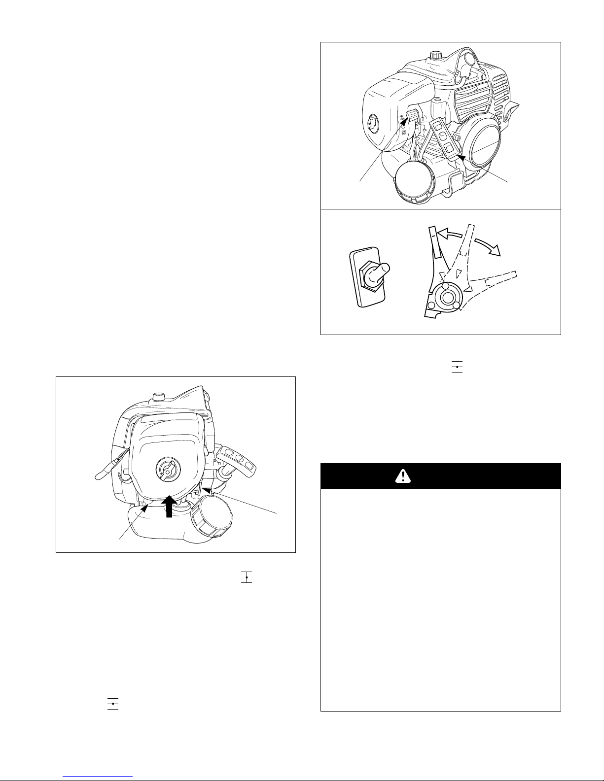
Cold Starting Procedure
This Water Pump is equipped with a fuel primer and a
choke system. To start a “cold” engine properly, perform the following procedure:
1. Pump the primer bulb at the bottom of the carburetor until fuel can be seen flowing through the
fuel return line to the fuel tank.
(Flowing fuel should be almost clear, not foamy or
full of bubbles.)
2. Move the choke lever to the closed ( ) position
and move the stop switch to the “ON” position.
3. With the stop switch “ON”,and the throttle lever
positioned at 1/3 throttle position, then pull the
starter grip.
4. After the engine starts, move the throttle lever to
the idle position, then move the choke lever to the
open ( ) position.
If the engine stops running before you move the
choke lever to the open ( ) position:
A. Go ahead and open the choke.
B. Make sure the throttle lever is set to the 1/3
throttle position.
C. Pull the starter grip until the engine starts.
O N
OFF
STOP
SWITCH
IDLE POSITION
THROTTLE LEVER
FULL
THROTTLE
POSITION
1/3 THROTTLE
POSITION
Primer Bulb
Fuel
Return
Line
Starter Grip
Choke Lever
WARNING
POTENTIAL HAZARD
• The components of your recoilstarter
assembly are under high spring tension.
If improperly disassembled these par ts
maystrike you with considerable force,
possibly causing personal injuly.
WHAT CAN HAPPEN
• Contact with the par ts can cause severer personal injury.
HOW TO AVOID THE HAZARD
• Never attempt to disassemble your
recoil starter assembly yourself.
Always consult your authorized
Maruyama dealer for r epair by qualified
service technicians.
Page 20
— 19 —
Hot Restart
To start an engine that is already warmed up (hot
restart), or if the ambient temperature exceeds 68°F
(20°C):
1. Pump the primer bulb at the bottom of the carburetor until fuel can be seen flowing through the
fuel return line to the fuel tank.
2. Move the choke lever to the open ( ) position
and move the stop switch to the “ON” position.
3. Leave the throttle lever in the idle position and
pull the starter grip.
4. If the engine fails to start after three to four pulls,
follow the instruction in the Cold Starting
Procedure section (page 18).
If the engine fails to start after you follow the
above procedures, contact an authorized
Maruyama dealer.
To Stop The Engine:
1. Move throttle lever to the idle position.
2. Move the stop switch to the “OFF” position.
IMPORTANT: Except emergency, do not stop
engine while it runs fast. It may damage the
engine. Move the throttle lever at idle position
first, then move the stop switch to “OFF” position.
IMPORTANT: In case of the stop switch failure
and the engine continue to run, move the choke
lever to the closed () position to stop the
engine.
Carburetor Adjustment
This water pump is equipped with non-adjustable fuel
mixture carburetor. The engine idle speed is the only
adjustment accessible to the Operator .
CAUTION: The water pump impeller is spinning during
idle speed adjustment.
Never start the engine without water in the pump housing.
Running the engine without water in the pump housing
will cause serious damage.
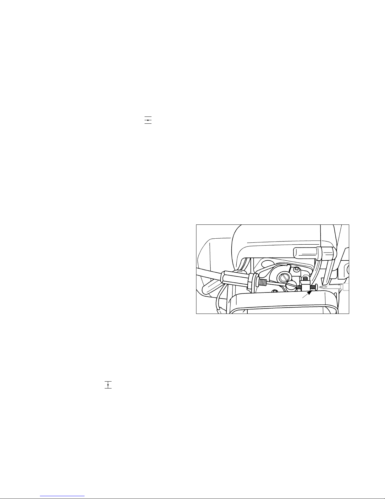
Engine Idle Speed:
The engine idle speed should be 2,700-3,300 rpm.
The engine idle speed is adjusted by rotating the idle
speed screw on the carburetor.
Turning the idle speed screw in (clockwise) increase
engine speed while turning the screw out decreases
engine speed.
Idle Speed
Adjuster Screw
Page 21
— 20 —
Maintenance
Maintenance, replacement or repair of emission
control devices and systems may be performed by
any repair establishment or individual; however,
warranty repairs must be performed by a dealer or
service center authorized by Maruyama
Manufacturing Company, Inc. The use of parts that
are not equivalent in performance and durability to
authorized parts may impair the effectiveness of the
emission control system and may have a bearing on
the outcome of a warranty claim.
Pump
1. After the pump has been used with muddy water,
be sure to run it with clean water for a few minutes
to clean the interior of the pump before stopping
operation.
2. Where outside temperatures drop to freezing or
below, be sure to drain all water from the pump
before storage.
3. When the unit is not to be used for a long period of
time, clean the pump interior thoroughly, remove
all remaining moisture, and then store it covered in
a dry, cool, dark place.
Air Filter
Maintenance Interval
• The air filter should be cleaned daily, or more
often when working in extremely dusty conditions.
• Replace after every 100 hours of operation.
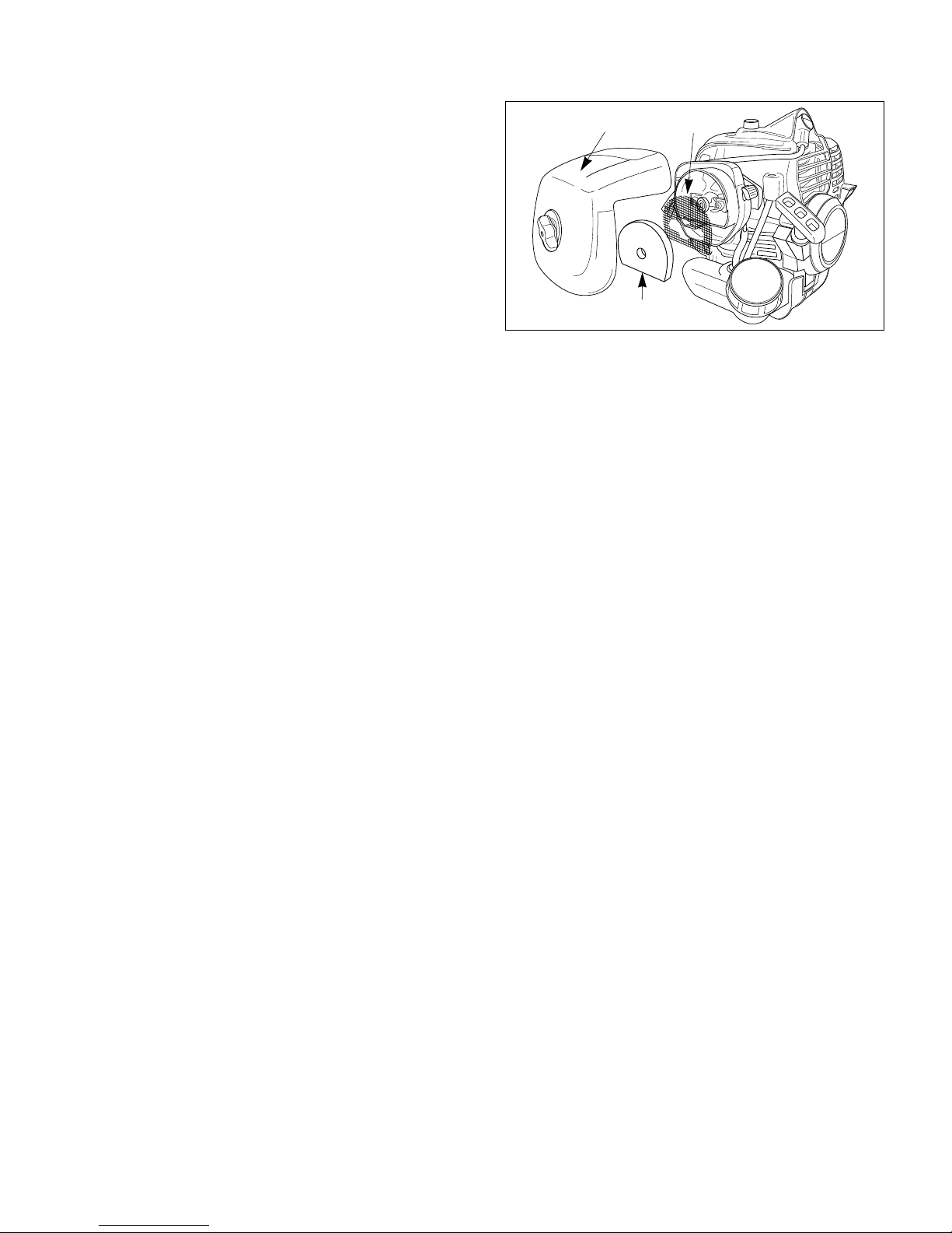
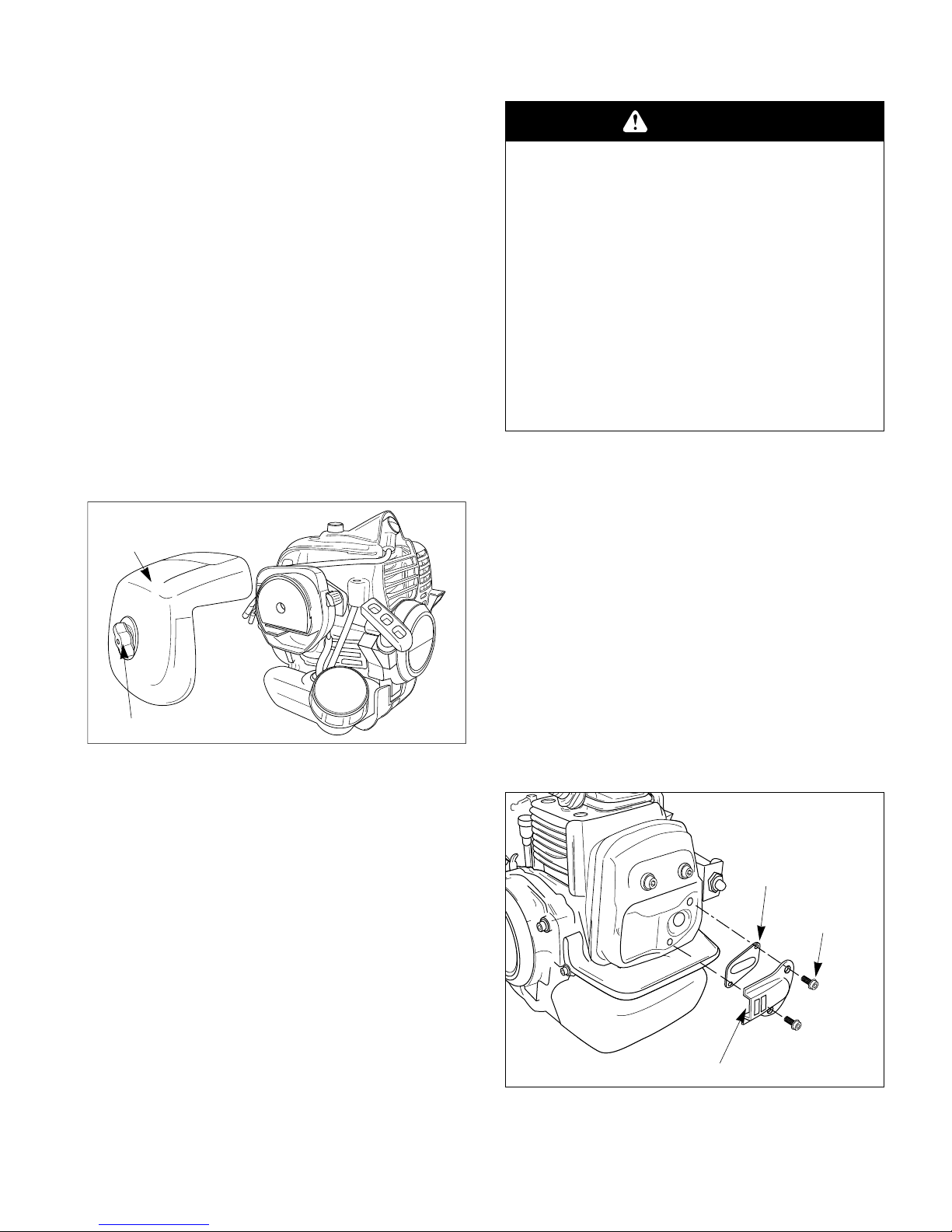
Air Filter Cleaning
1. Loosen the knob and remove the air filter cover.
2. Remove the foam element and filter screen from
the air filter body.
3. Clean the foam element and filter screen with
warm, soapy water. Let the screen and element dry
completely .
4. Apply a light coat of SAE 30 motor oil to the foam
element and squeeze out all excess oil.
5. Reassemble the filter screen and foam element to
the air filter body.
6. Reinstall the air filter cover and tighten the knob.
Air Filter Cover
Foam Element
Filter Screen
Page 22
— 21 —
Fuel Filter
Maintenance Interval
The fuel filter should be replaced after every 100 hours
of operation.
Fuel Filter Replacement
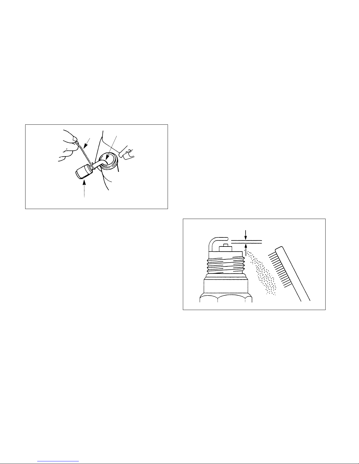
The fuel filter is attached to the end of the fuel pick-up
hose inside the fuel tank.
To replace the fuel filter:
1. Make sure the fuel tank is empty.
2. Remove the fuel cap.
3. Using a wire hook, gently pull the fuel filter out
through the fuel filler opening.
4. Grasp the fuel hose next to the fuel filter fitting
and remove the filter, but do not release the hose.
5. While still holding on to the fuel hose, attach the
new fuel filter.
6. Drop the new fuel filter back into the fuel tank.
7. Make sure that the fuel filter is not stuck in a corner of the tank, and that the fuel hose is not doubled over (kinked) before refueling.
Spark Plug
Maintenance Interval
• The spark plug should be removed from the
engine and checked after each 25 hours of operation.
• Replace the spark plug after every 100 hours of
operation.
Spark Plug Maintenance
1. Twist the high tension lead boot on the spar k plug
back and forth a couple of times to loosen the
boot, then pull the boot off of the spark plug.
2. Remove the spark plug.
3. Clean the electrodes with a stiff brush.
4. Adjust the electrode air gap to .024-.028 in (0.6-
0.7 mm).
5. Replace the spark plug if it is oil-fouled, damaged,
or if the electrodes are worn down.
6. Do not overtighten the spark plug when installing.
The tightening torque is 95-148 in. lbs. (10.7-16.6
N·m).
Wire
Fuel Pick-up Hose
Fuel Filter
.024” - .028” (0.6 - 0.7 mm)
Page 23
— 22 —
Cylinder Cooling Fins
Maintenance Interval
The cylinder cooling fins should be cleaned after every
25 hours of operation, or once a week, whichever
comes first.
Air must flow freely around and through the cylinder
cooling fins to prevent engine overheating. Leaves,
grass, dirt and debris buildup on the fins will increase
the operating temperature of the engine, which can
reduce engine performance and shorten engine life.
Cooling Fin Cleaning
1. With the engine at ambient (room) temperature,
loosen the knob and remove the air cleaner cover.
2. Twist the high tension lead boot on the spar k plug
back and forth a couple of times to loosen the
boot, then pull the boot off of the spark plug.
3. Loosen the knob and lift off the cylinder cover.
4. Clean all dirt and debris from the cooling fins and
from around the cylinder base.
5. Reinstall the fan cover and the cleaner cov er.
Spark Arrester
Maintenance Interval
• The spark arrester should be inspected and
cleaned after every 25 hours of use.
• Replace the screen if it cannot be thoroughly
cleaned, or if it is damaged.
Spark Arrester Maintenance
1. With the engine at ambient (room) temperature,
Remove the tapping screw, and remove the cover.
2. Twist the high tension lead boot on the spar k plug
back and forth a couple of times to loosen the
boot, then pull the boot off of the spark plug.
3. Loosen the knob and lift off the cylinder cover.
Air Cleaner Cover
Knob
WARNING
POTENTIAL HAZARD
• Muffler sur face becomes hot when
Water Pump is in operation and
remains hot for some time after the
engine is shut off.
WHAT CAN HAPPEN
• Contact with hot muffler surfaces could
cause a burn.
HOW TO AVOID THE HAZARD
• Make sure the muffler is cool before
inspecting and cleaning the spark
arrester.
Socket Head Screw
Tail
Spark Arrester
Page 24
4. Remove and clean the tail, gasket and spark
arrester with a safety solvent and a stiff brush. If
any part cannot be thoroughly cleaned, it must be
replaced.
5. Reinstall the spark arrester and tail onto the muffler, then reinstall and tighten the two socket head
screws.
6. Reinstall the cylinder cover and the air cleaner
cover.
Exhaust Muffler
Maintenance Interval
The muffler should be inspected and cleaned after each
100 hours of use.
Muffler Maintenance
1. With the engine at ambient (room) temperature,
loosen the knob and remove the air cleaner cover.
2. Twist the high tension lead boot on the spar k plug
back and forth a couple of times to loosen the
boot, then pull the boot off of the spark plug.
3. Loosen the knob and lift off the cylinder cover.
4. Remove the spark arrester (see spark arrester
maintenance), Clean the muffler with a stiff brush.
5. Reinstall the spark arrester and tail onto muffler,
then reinstall and tighten the two socket head
screws.
6. Reinstall the cylinder cover and the air cleaner
cover.
IMPORTANT: Be careful not to allow any dirt
or debris to fall into the exhaust port, as this
can cause engine damage.
Storage
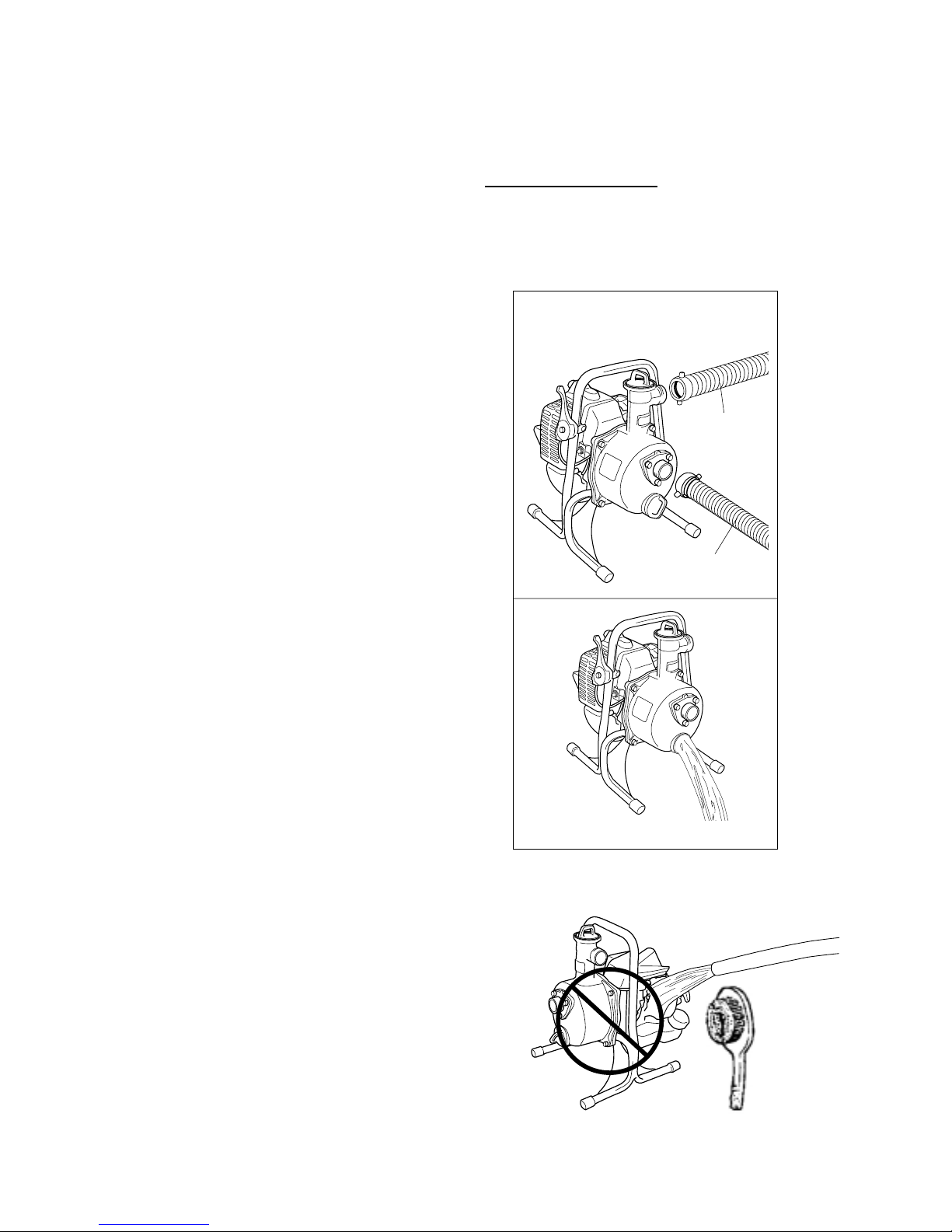
For long term storage of the Water Pump:
PUMP SECTION
1. Drain water from the pump completely.
2. Remove Suction hose and Discharge hose from
pump.
IMPORTANT: Do not wash the pump in w ater. It
may damage the engine.
— 23 —
Remove Suction Hose and Discharge
Hose from the Pump
Drain water from Pump completely
Discharge Hose
Suction Hose
Do not wash the pump in water
Page 25
— 24 —
ENGINE SECTION
1. Empty the fuel tank into a suitable fuel storage
container.
2. Pump the primer bulb on the carburetor until all
fuel is discharged through the clear fuel return
hose.
3. Run the engine to remove any fuel that may
remain in the carburetor.
4. Perform all regular maintenance procedures and
any needed repairs.
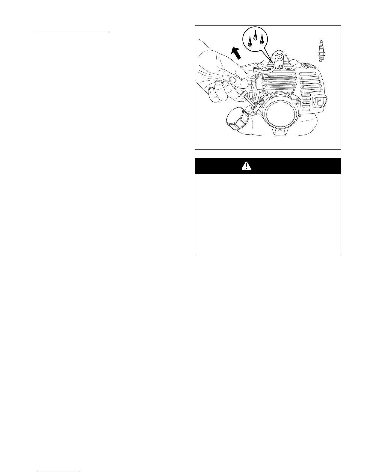
5. Remove the spark plug and squirt a very small
amount of oil into the cylinder .
6. Pull the starter grip once.
7. Slowly pull the starter grip to bring the piston to
the top of the cylinder (TDC).
8. Reinstall the spark plug.
9. Store the Water Pump in a dry place away from
excessive heat, sparks or open flame.
CAUTION
POTENTIAL HAZARD
• Oil may squirt out of the spark plug opening when you pull the starter grip.
WHAT CAN HAPPEN
• Oil can cause eye injuries.
HOW TO AVOID THE HAZARD
• Protect your eyes and keep your face
away from the spark plug opening.
Page 26
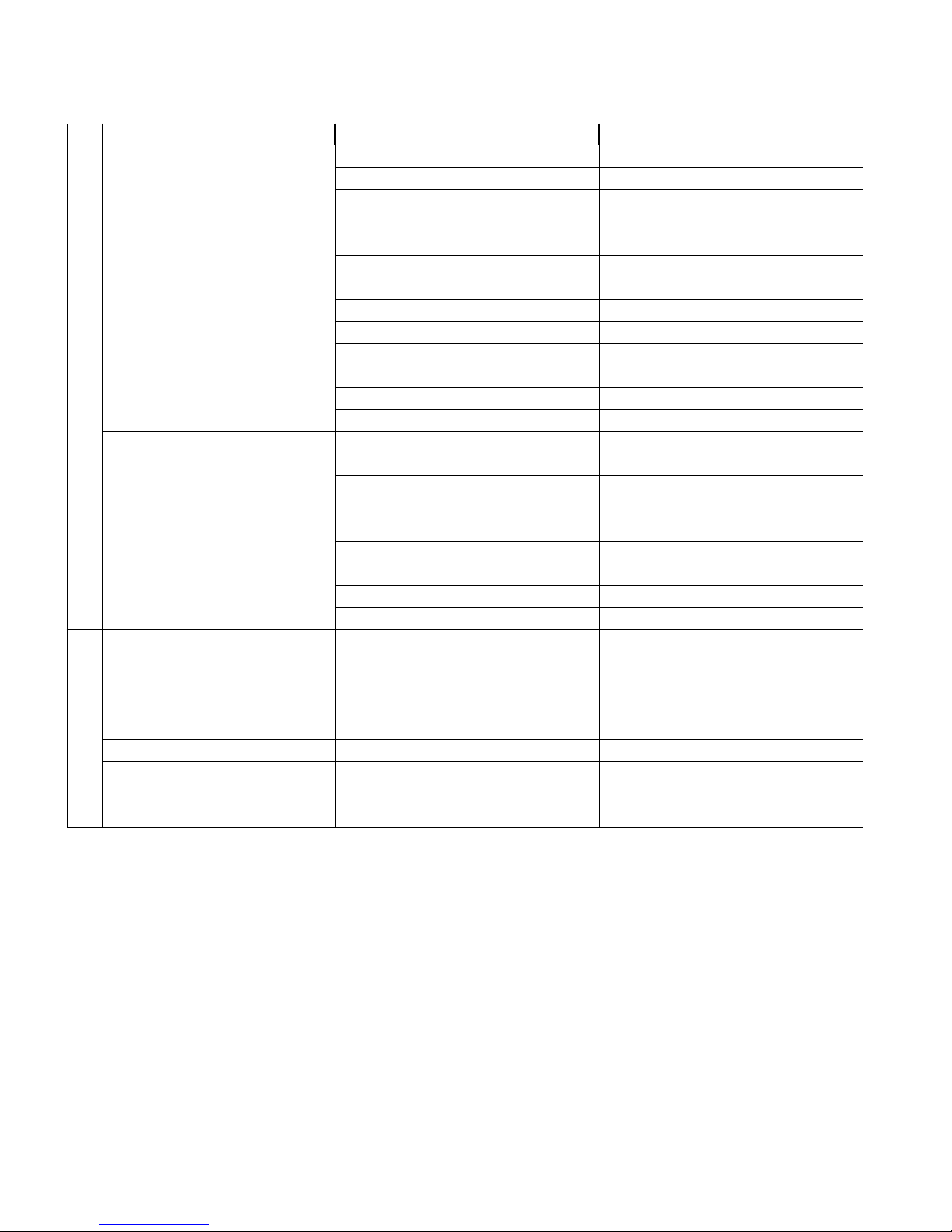
— 25 —
Pump
Engine
Troubleshooting
If further assistance is required, contact your local authorized Maruyama service dealer.
Problem Cause Action
Pump doesn't rotate
No suction or suction time is
long
Low discharge volume
Low discharge pressure
Engine Will Not Start
Engine Will Not Idle
Engine Lacks Power or Stalls
When Cutting
Engine doesn't move
Impeller rusted
Debris is stuck in Impeller.
Air is being drawn in
Priming water is not sufficient
Mechanical seal failure
Engine rpm is too low
Pump position is too high from
water source
Suction hose is damaged or folded
Strainer or hose is clogged
Air is being drawn in
Engine rpm is too low
Pump position is too high from
water source
Impeller is worm
Suction hose diameter is too small
Debris is stuck in Impeller.
Strainer or hose is clogged
STOP switch set to off position
Empty fuel tank
Primer bulb wasn't pushed enough
Engine flooded
Idle speed set incorrectly
Throttle wire has come loose
Dirty air filter
Clogged spark arrester or exhaust
port.
Refer to engine troubleshooting.
Disassemble and repair
Disassemble and clean
Check all connections and tighten
them.
Fill the pump casing with priming
water until it is full
Replace mechanical seal
Increase engine rpm
Place pump near water source
Replace suction hose
Check and clean
Check all connections and tighten
them.
Increase engine rpm
Place pump near water source
Replace Impeller
Use bigger diameter suction hose
Disassemble and clean
Check and clean
Move switch to on position
Fill fuel tank
Press primer bulb until fuel flows
through fuel return line
Use warm engine starting procedure
Set idle speed
Tighten throttle wire
Clean or replace air filter
Clean spark arrester or exhaust port
Page 27
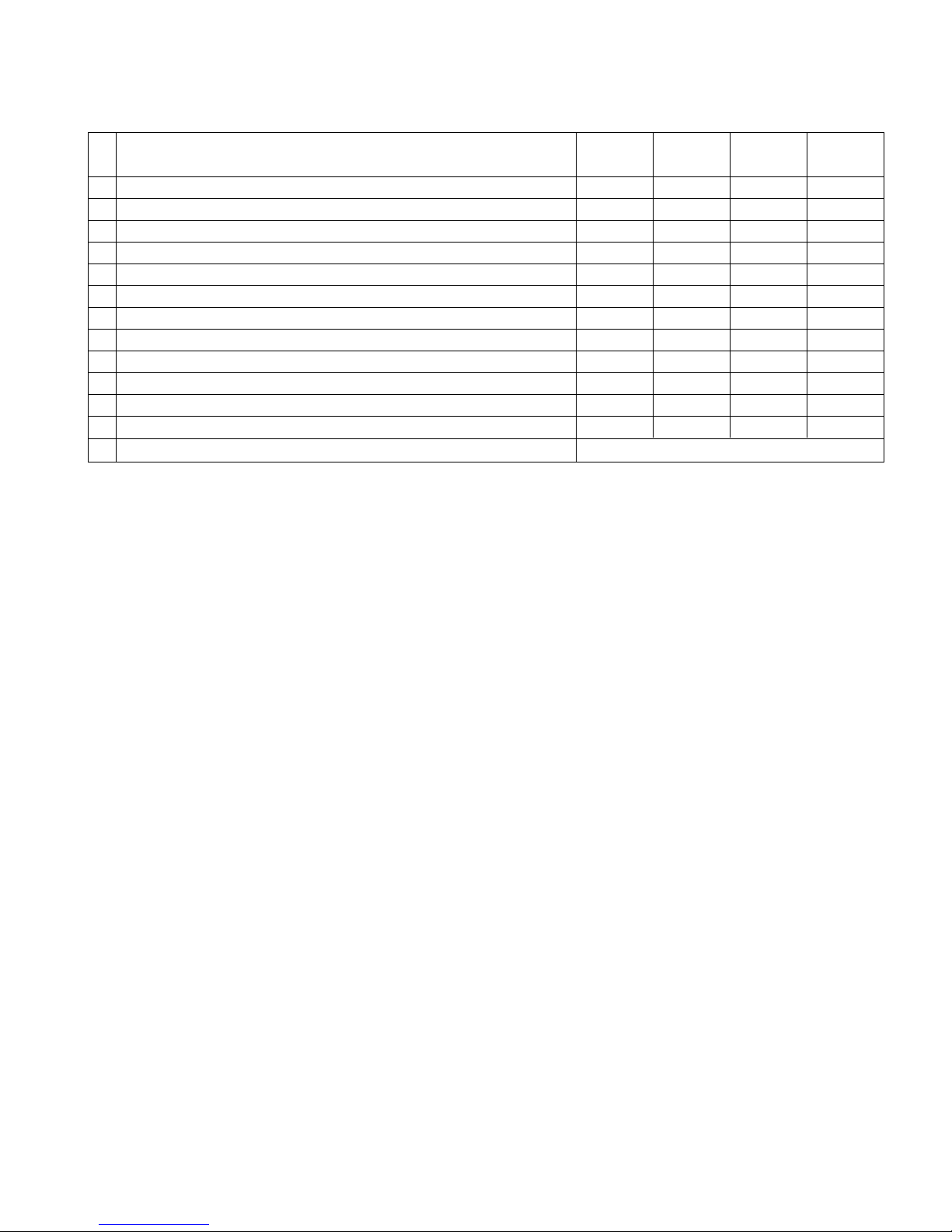
— 26 —
Every Every Every
Maintenance Daily 20 hours 50 hours 100 hours
Check and replenish fuel
●
Check for fuel leakage
●
Check bolts, nuts and screws for tightness or missing
●
Tighten bolts and nuts
●
■
Clean air filter element
●
Clean spark plug and adjust electrode gap
●
■
Remove dust and dirt from cylinder fins
●
●
Remove carbon deposits in exhaust port
●
●
Clean spark arrester
●
Replace fuel filter
●
●
Remove carbon deposits on piston head and combustion chamber
●
●
Remove carbon deposits in transfer ports
●
Replece fuel tube, fuel tank cap gasket It is recommended to replace every 3 years
Maintenance P eriod
●
: Service to be performed by an authorized Maruyama engine dealer.
■
: Service more frequently under dusty conditions.
NOTE:
The service intervals indicated are to be used as a guide.
Service to be performed more frequently as necessary depending on operating condition.
Use Maruyama standard 50:1 two-cycle engine oil.
Page 28

Maruyama U.S., Inc.
3570 Shelby Lane
Denton, TX 76207 U.S.A
P.O. Box 2107
Denton, TX 76202 U.S.A
Phone 940-383-7400
Fax 940-383-7466
www.maruyama-us.com
284680-03 10.10 TAP/M
 Loading...