

Page 1

- 0 -
MC-S
(
String Trimmer Attachment
)
MC-HT
(Hedge Trimmer Attachment)
MC-T
(
Cultivator Attachment
)
MC-E
(Edg
er Attachment
)
MC-PS
(
Pruner Attachment
)
MC2600RS
(
Multi-Cutter Power Unit
)
MC-HTS
(Hedge Trimmer Attachment)
Owner’s/Operator’s Manual
Completely read and understand this manual before using this product.
Page 2

- 1 -
Foreword
This Owner’s/ Operator’s Manual is designed to familiarize the operator with the various features and
component parts of the equipment and to assist you with the assembly, operation and maintenance of
your new Multi-cutter.
It is essential that any operator of this Multi-cutter reads and understands the contents this manual
before using the Multi-cutter.
For additional assistance, contact any local authorized MARUYAMA dealer.
Contents
Foreword
……………………………………………………………………………………………………
Contents
…………………………………………………………………………………………………
Safety
Instructions
…………………………………………………………………………………………
Operator Safety
…………………………………………………………………………………………
Multi-cutter Safety
………………………………………………………………………………………
Fuel Safety
………………………………………………………………………………………………
Multi-cutter Operating Safety
…………………………………………………………………………
Safety and Instruction Decals
…………………………………………………………………………
Product Description
…………………………………………………………………………………………
Assembly
……………………………………………………………………………………………………
Loop Handle Installation
…………………………………………………………………………………
MC-S(String Trimmer Attachment)
……………………………………………………………………
MC-E(Edger Attachment)
………………………………………………………………………………
MC-HTS
(
Hedge Trimmer Attachment)
……………………………………………………………
MC-PS(Pruner Attachment)
……………………………………………………………………………
MC-T(Cultivator Attachment)
…………………………………………………………………………
Connecting the Tool Attachment to the Power Unit
…………………………………………………
Before Operation
…………………………………………………………………………………………
Chain Oil
(
Multi-cutter with Pruner Attachment)
……………………………………………………
Engine Oil and Fuel
……………………………………………………………………………………
Mixing Gasoline And Oil
………………………………………………………………………………
Starting and Stopping
…………………………………………………………………………………
Idle Speed Adjustment
…………………………………………………………………………………
Operation
……………………………………………………………………………………………………
MC-S
(
Multi-cutter with String Trimmer Attachment)
………………………………………………
MC-E
(
Multi-cutter with Edger Attachment)
…………………………………………………………
MC-HT/MC-HTS
(
Multi-cutter with Hedge Trimmer Attachment)
………………………………
MC-PS
(
Multi-cutter with Pruner Attachment)
………………………………………………………
MC-T
(
Multi-cutter with Cultivator Attachment)
……………………………………………………
Maintenance
………………………………………………………………………………………………
Air Filter
…………………………………………………………………………………………………
Fuel Filter
………………………………………………………………………………………………
Spark Plug
………………………………………………………………………………………………
Cylinder Cooling Fins
…………………………………………………………………………………
Spark Arrester
…………………………………………………………………………………………
MC-S(String Trimmer Attachment)
…………………………………………………………………
MC-E(Edger Attachment)
……………………………………………………………………………
MC-HT/MC-HTS
(
Multi-cutter with Hedge Trimmer Attachment)
………………………………
MC-T(Cultivator Attachment)
…………………………………………………………………………
General Cleaning and Tightening
………………………………………………………………………
Storage
……………………………………………………………………………………………………
Troubleshooting
……………………………………………………………………………………………
Specifications
………………………………………………………………………………………………
1
1
2
2
2
3
3
4
6
7
7
7
9
10
10
11
12
12
12
12
13
14
15
16
16
19
20
22
23
24
24
24
24
25
26
26
27
28
29
29
29
30
30
Page
Page 3

- 2 -
Safety Instructions
The warning system in This manual identifies potential hazards and has special safety messages that
help you and others avoid personal injury, even death.
, and are signal words to identify the level of hazard.
: signals an extreme hazard that will cause serious injury or death if the recommended
precautions are not followed.
: signals a hazard that may cause serious injury or death if the recommended
precautions are not followed.
: signals a hazard that may cause minor or moderate injury if the recommended
precautions are not followed. Two other words are also used to highlight information.
“Important” calls attention to special mechanical information and “Note” emphasizes
general information worthy of special attention.
Operator safety
1. Read and understand this Manual before using the Multi-cutter. Be thoroughly familiar with the
proper use of this Multi-cutter.
2. Always wear eye protection and hearing protection.
3. Always wear heavy long pants, a long sleeved shirt, boots and gloves. Do not wear loose clothing,
jewelry, short pants, sandals, or go barefoot. Secure hair so it is above shoulder length.
4. Never operate this Multi-cutter when you are tired, ill, or under the influence of alcohol, drugs or
medication.
5. Never start or run the engine inside a closed room or building. Breathing exhaust fumes can cause
death.
6. Keep the grip of handles clean of oil, fuel and dirt.
Multi-cutter safety
1. Make sure the Multi-cutter is assembled correctly and that the tool attachment is correctly installed
and securely fastened as instructed in the Assembly section beginning on page 7.
2. Inspect the Trimmer/ Brushcutter before each use. Replace damaged parts. Check for fuel leaks.
Make sure all fasteners are in place and tightened securely. Follow the Maintenance instructions
beginning on page 24.
3. Shut off the engine and be certain the attached tool has completely stopped moving before
inverting the Multi-cutter, performing maintenance on or working on the machine.
4. Make sure the attached tool does not move at engine idle speed. Refer to Idle Speed Adjustment,
page 15.
5. Inspect the tool attachment and replace any parts that are cracked, chipped or damaged before
using the Multi-cutter.
6. Never use a tool attachment or replacement parts that are not approved by MARUYAMA.
CAUTION WARNING DANGE
R
DANGE
R
WARNING
CAUTION
Page 4

- 3 -
7. Maintain the Multi-cutter according to the recommended maintenance intervals and procedures in
the Maintenance section beginning on page 24.
8. If running problems or excessive vibration occur, stop immediately and inspect the unit for the
cause. If the cause cannot be determined or is beyond your ability to correct, return the Multi-cutter
to your servicing MARUYAMA dealer for repair.
Fuel safety
1. Gasoline is highly flammable and must be handled and stored carefully. Use a container approved
for fuel for storing gasoline and/or fuel/oil mixture.
2. Mix and pour fuel outdoors and where there are no sparks or flames.
3. Do not smoke near fuel or Multi-cutter, or while using the Multi-cutter.
4. Do not overfill the fuel tank. Stop filling 10mm from the top of the tank.
5. Wipe up any spilled fuel before starting the engine.
6. Move the Multi-cutter at least 3m away from the fueling location before starting the engine.
7. Do not remove the Multi-cutter fuel tank cap immediately after stopping the engine.
8. Allow the engine to cool before refueling.
9. Drain the tank and run the engine dry before storing the unit.
10. Store fuel and Multi-cutter away from open flame, sparks and excessive heat. Make sure fuel
vapors cannot reach sparks or open flames from water heaters, furnaces, electric motors, etc.
Multi-cutter Operating safety
1. THIS MULTI-CUTTER CAN CAUSE SERIOUS INJURIES. Read the instructions carefully. Be
familiar with all controls and the proper use of the Multi-cutter.
2. Never allow children to operate the Multi-cutter. It is not a toy. Never allow adults to operate the unit
without first reading this Operator’s Manual.
3. Avoid using the Multi-cutter near rocks, gravel, stones and similar material that would cause
harmful missiles.
4. Keep children, bystanders and animals outside a 50ft.(15m)
radius from the operator and Multi-cutter.
5. If you are approached while operating the Multi-cutter, stop
the engine and attached tool moving.
6. Use the Multi-cutter only in daylight or good artificial light.
50ft.(15m)
Minimum
Page 5

- 4 -
7. Never operate the Multi-cutter without proper guards in place.
8. Do not put hands or feet near or under any moving parts. Keep clear at all times. Keep all parts of
your body away from the moving tool attachment and hot surfaces such as the muffler.
9. Keep a firm footing and balance. Do not overreach.
10. Use the right tool for the job. Do not use the Multi-cutter for any job that is not recommended by
MARUYAMA.
Safety and Instruction Decals
Safety decals and instructions are easily visible to the operator and are located near any
area of potential danger. Replace any that are damaged or lost.
MC-HT (Hedge Trimmer Attachment)
ON SHAFT
(Part No. 221501)
ON SHAFT
(Part No. 217879)
ON SHAFT
(Part No. 221502)
ON BLADE GUIDE PLATE
(
Part No. 591450
)
CAUTION
: Extremely sharp blades. Do not touch.
ON BLADE GUARD
(Part No. 221528)
MC-S (String Trimmer Attachment)
MC-E (Edger Attachment)
MC2600RS (Multi-Cutter Power Unit)
ON ENGINE
(Part No. 267433)
N452
ON ENGINE
(Part No. 283375)
ON GEARCASE
(Part No. 223925)
Add grease to
gearcase every
10 hours of use.
ON SHAFT
(Part No. 221501)
ON SHAFT
(Part No. 221502)
Page 6

- 5 -
MC-HTS (Hedge Trimmer Attachment)
MC-PS (Pruner Attachment)
MC-T (Cultivator Attachment)
ON SHAFT
(Part No. 219937)
ON SHAFT
(Part No. 221501)
ON SHAFT
(Part No. 221502)
ON SHAFT
(Part No. 221501)
ON SHAFT
(Part No. 221502)
ON GEARCASE
(Part No. 407349)
ON SHAFT
(Part No. 221501)
ON SHAFT
(Part No. 217879)
Page 7

- 6 -
6
6
Product Description
MC-E
(Edger Attachment)
MC-HT
(Hedge Trimmer Attachment)
MC-PS
(Pruner Attachment)
MC-T
(Cultivator Attachment)
1. Gearcase
2. Shaft Assembly
3. Safety Decal
4. Guard
1. Blade Guard
2. Shaft Assembly
3. Wheel
4. Gearcase
5. Edger Blade
6. Safety Decal
1. Blade and Guide Bar
2. Gearcase
3. Angle Drive
4. Shaft Assembly
5. Safety Decal
6. Blade Sheath
1. Chain and Guide Bar
2. Pruner Head
3. Shaft Assembly
4. Gearcase
5. Safety Decal
1. Cultivator Tine
2. Gearcase
3. Shaft Assembly
4. Shield
5. Safet
y
Decal
1
2
3
4
MC-HTS
(Hedge Trimmer Attachment)
MC2600RS
(Multi-Cutter Power Unit)
1. Shaft connector
2. Loop Handle
3. Shaft Assembly
4. Attachment Ring for Shoulder Hanging Strap
5. Shaft Grip
6. Clutch Drum Housing
7. Engine
8. Air Filter
9. Fuel Tank
10. Throttle Cable and Stop Switch Wires
11. Throttle Trigger and Stop Switch
12. Safety Decal
13. Shoulder Hanging Strap
7
8
9
10
11
6
3
2
1
5
13
12
12
4
1. Blade and Guide Bar
2. Gearcase
3. Angle Drive
4. Shaft Assembly
5. Safety Decal
6. Blade Sheath
2
1
4
3
3
2
1
5 4
6
6
3
2
1
5
5
4
3
2
1
4
5
5
1
2
3
4
5
5
MC-S
(String Trimmer Attachment)
Page 8

- 7 -
Assembly
Loop Handle Installation
1. Place the loop handle and the bottom clamp on the shaft
approximately 28cm(11 inches) from the end of the stop switch/
throttle trigger assembly.
2. Install the four screws and nuts. Tighten the screws evenly.
3. Reposition the loop handle up or down the driveshaft to the
most comfortable position, and tighten the screw and nuts.
MC-S(String Trimmer Attachment)
Installing Guard
1. Fasten the string cutoff blade to the guard with
M5×15 screws as shown on Fig.2.
2. Atttach the guard to the shaft with the two M5x30
screws and plate as shown.
Installing Trimmer Head
1. Align the hole in the boss adapter with the guide slot in the
gearcase.
2. Insert the φ3.5mm pin into the hole in the boss adapter and the guide slot in the gearcase to lock the
attaching shaft.
3. Thread the trimmer head adapter into the attaching shaft, then tighten the trimmer head by hand.
Note: The trimmer head adapter has left-hand thread.
4. Remove the φ3.5mm pin from the boss adapter and gearcase.
WARNING
POTENTIAL HAZARD
・If the cutting attachment is not adequately tightened,
it can come loose from the String Trimmer Attachment
during use.
WHAT CAN HAPPEN
・This may cause damage to property or personal injury.
HOW TO AVOID THE HAZARD
・Make sure the cutting attachment head is securely
fastened to the attaching shaft in the gearcase.
Loop Handle
Screw
(4)
Bottom Clamp
Nut(4)
Trimmer
Head
Adapter
Attaching
Shaft
Gearcase
Boss
Adapter
Holding Tool
(φ3,5mm Pin)
Trimmer
Head
Left-hand
thread
Clamping
Washer
M5X30
Screw(2)
Gear Case
Shaft
Guard
M5X15
Screw(2)
Plate
Hex Nut
Fig.2
String Cutoff Blade
WARNING
POTENTIAL HAZARD
・Foreign objects can be thrown by Edger.
WHAT CAN HAPPEN
・Contact with thrown objects can cause personal
injury.
HOW TO AVOID THE HAZARD
・Never operate the Multi-cutter without the blade
guard.
Page 9
- 8 -
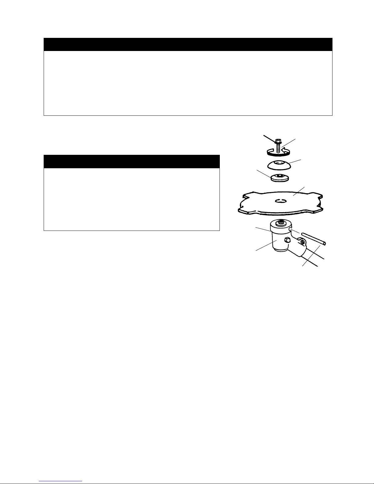
Brushcutter Blade
1. Remove the blade bolt, stabilizer and clamping washer
from the attaching shaft out of the gearcase.
Note: The blade bolt has left-hand thread.
2. Install the brushcutter blade onto the boss adapter, then
reinstall the clamping washer, stabilizer and blade bolt.
3. Align the hole in the boss adapter with the guide slot in the
gearcase.
4. Insert the φ3,5mm pin into the hole in the boss adapter and the guide slot in the gearcase to lock the
attaching shaft.
5. Tighten the blade bolt.
6. Remove the φ3,5mm pin from the boss adapter and gearcase.
WARNING
POTENTIAL HAZARD
・If the Brushcutter blade is not adequately tightened, it can come loose from the Brushcutter
during use.
WHAT CAN HAPPEN
・This may cause damage to property or personal injury.
HOW TO AVOID THE HAZARD
・Make sure the Brushcutter blade is securely fastened to the attaching shaft in the gearcase.
WARNING
POTENTIAL HAZARD
・Brushcutter blade is sharp.
WHAT CAN HAPPEN
・Contact with sharp blade can cause personal injury.
HOW TO AVOID THE HAZARD
・Wear gloves when you handle the blade.
Brushcutter Blade
Clamping
Washer
Stabilizer
Blade Bolt
Left-hand
thread
Gearcase
Boss
Adapter
Holding Tool
(φ3,5mm Pin)
Page 10
- 9 -
MC-E(Edger Attachment)
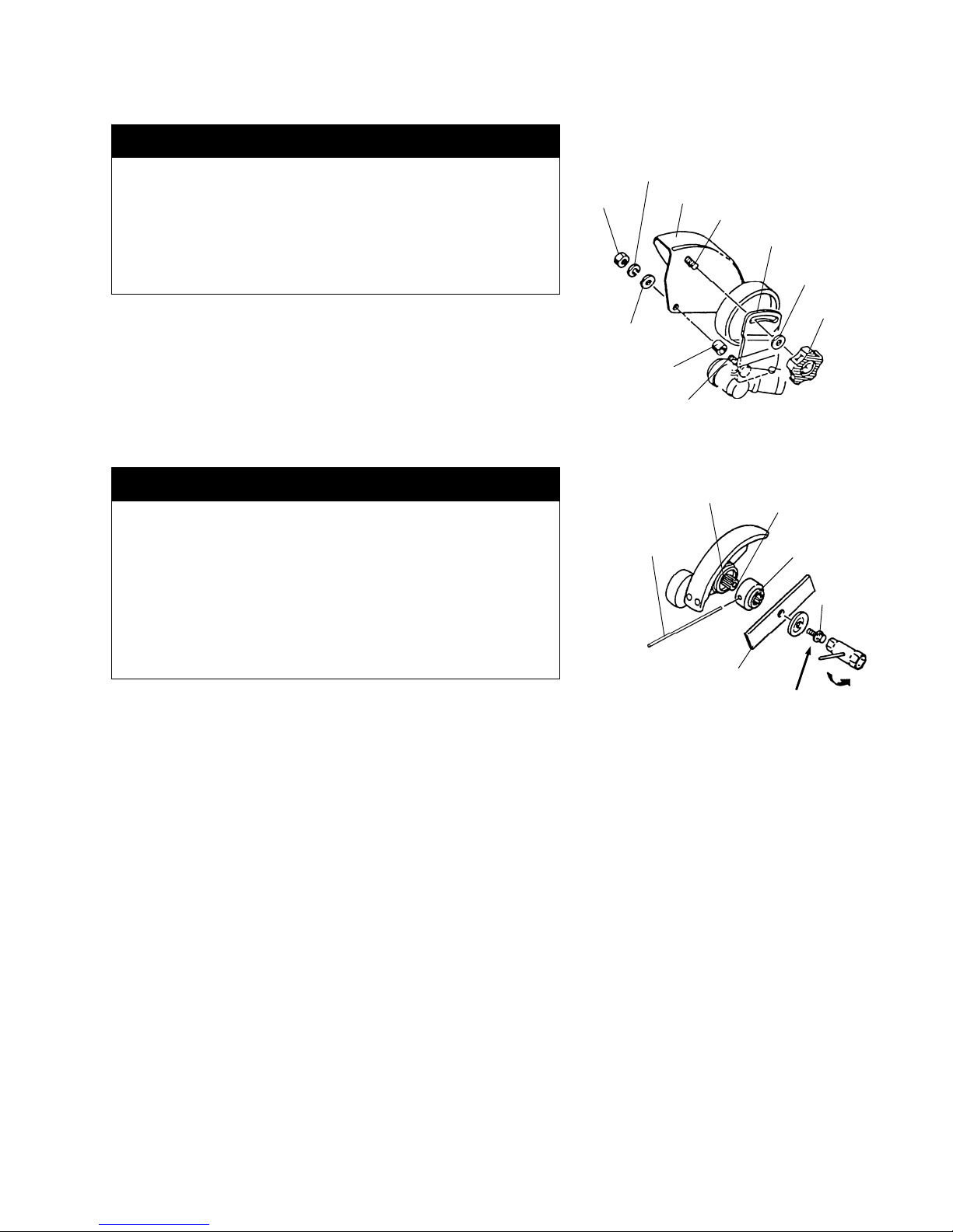
Installing Guard
1. Install the collar onto the plate stud.
2. Install the Guard onto the plate stud, making sure the Guard stud
fits into the matching slot in the plate.
3. Install the flat washer, lock washer and hex nut onto the plate stud.
4. Install the flat washer and knob onto the Guard.
1. Install the boss onto the attaching shaft out of the gearcase.
2. Install the edger blade, clamping washer and blade bolt.
Note: The blade bolt has left-hand thread.
3. Align the hole in the boss adapter with the guide slot in the gearcase.
4. Insert the φ3.5mm pin into the hole in the boss adapter and the guide
slot in the gearcase to lock the attaching shaft.
5. Tighten the blade bolt to 11.3 Nm (100 in. -lbs.).
6. Remove the φ3.5mm pin from the boss adapter and gearcase.
Edger Blade
Blade Bolt
Gearcase
Holding Tool
(φ3.5mm Pin)
Ataching Shaft
Boss Adapter
Left-hand
thread
WARNING
POTENTIAL HAZARD
・If the Edger blade is not adequately tightened, it can
come loose from the Edger during use.
WHAT CAN HAPPEN
・This may cause damage to property or personal injury.
HOW TO AVOID THE HAZARD
・Make sure the Edger blade is securely fastened to the
attaching shaft in the gearcase.
WARNING
POTENTIAL HAZARD
・Foreign objects can be thrown by Edger.
WHAT CAN HAPPEN
・Contact with thrown objects can cause personal injury.
HOW TO AVOID THE HAZARD
・Never operate the Edger without the blade guard.
Plate
Knob
Flat Washer
Lock Washer
Hex Nut
Flat Washer
Collar
Guard
Guard Stud
Plate Stud
Page 11

- 10 -
MC-HTS(Hedge Trimmer Attachment)
Installing Shaft and Gearcase
Attach the driveshaft tube assembly to the Hedge Trimmer gearcase assembly.
Note: Carefully inspect both ends of the drive shaft protruding
from the drive shaft tube. The squared end of the drive
shaft positions toward the connector of the power unit.
The splined end of the drive shaft connector to the
gearcase assembly while rotating the drive shaft to engage
the splines. Align the locating holes and install the locating
screw through the side of the gearcase. Then tighten the clamping
screws. If properly installed, rotating the square end of the drive
shaft will cause the trimmer blades to move.
MC-PS (Pruner Attachment)
Installing Shaft and Gearcase
Attach the driveshaft tube assembly to the Hedge Trimmer
gearcase assembly.
Note: Carefully inspect both ends of the drive shaft protruding
from the drive shaft tube. The squared end of the drive
shaft positions toward the connector of the power unit.
The splined end of the drive shaft connector to the
gearcase assembly while rotating the drive shaft to engage
the splines. Align the locating holes and install the locating
screw through the side of the gearcase. Then tighten the clamping
screws. If properly installed, rotating the square end of the drive
shaft will cause the trimmer blades to move.
Installing Guide Bar and Chain
1. Remove the nuts from the two bar studs.
2. Fit the guide bar over the two bar studs. Do not engage the
chain tensioner adjustment pin hole at this time.
3. place the chain over the rim sprocket and into the groove on
the guide bar. Make sure the cutting teeth edges are facing
forward on the top side of the guide bar.
4. Pull the guide bar forward until the chain tensioner adjustment
pin hole is positioned over the chain tensioner adjustment pin.
If necessary, turn the chain tensioner screw in the appropriate
direction to align the pin with the hole. Check that the drive links
on the chain fit correctly into the rim sprocket and guide bar
groove.
Squared
Splined
Locating Hole
Clamping Screw
Locating
Screw
Gearcase
Shaft Assembly
Chain Tensioner
Adjustment Pin
Bar Stud
(2)
Chain Tensione
r
Screw
Guide Ba
r
Chain Tensioner
Adjustment
Pin Hole
Rim Sprocket
Chain
Guide Ba
r
Squared
Splined
Locating Hole
Clamping Screw
Locating
Screw
Gearcase
Shaft Assembly
Page 12

- 11 -
Bracket
Bracket
2.5cm
Gearcase
Screw 6mm
(2)
Plastic Colla
r
5. Install the sprocket cover onto the two bar studs. Install the bar
stud nuts, but leave the nuts finger-tight.
6. Rotate the chain tensioner screw until all slack is removed
between the chain and the bottom of the guide bar, but loose
enough to allow you to pull the chain around the guide bar by
hand.
7. Tighten the bar stud nuts and recheck the chain tension.
IMPORTANT: When using a new chain, you must check the chain tension frequently and adjust
the tension as necessary until the chain breaks in. A correctly adjusted chain gives optimum
cutting performance and prevents premature wear to both the chain and guide bar.
MC-T (Cultivator Attachment)
Installing shaft and Shield
Attach the driveshaft tube assembly to the cultivator gearcase
assembly.
NOTE: Carefully inspect both ends of the driveshaft
protruding from the driveshaft tube. The squared end of
the driveshaft positions toward the connector of the power
unit. The splined end of the driveshaft connects to the
cultivator gearcase assembly. Insert the driveshaft tube
assembly into the cultivator gearcase assembly while
rotating the driveshaft to engage the splines. Align the
locating holes and install the locating screw through
the side of the gearcase. Then tighten the clamping
screws. If properly installed, rotating the square end of
the driveshaft will cause the cultivator tines to turn.
Place the plastic collar onto the driveshaft tube
approximately 2.5cm from the cultivator gearcase, locating
the ends as shown in sketch. Then place the two bracket
parts onto the plastic collar and fasten securely with two
6 mm screws. Attach the shield to the bracket with four
5 mm screws.
Bracket
Shield
Screw
5mm(4)
Sprocket Cover
Chain Travel
Direction
Bar Stud Nuts
Squared
Splined
Locating Hole
Clamping Screw
Locating
Screw
Gearcase
Shaft Assembly
Page 13

- 12 -
Connecting the Tool Attachment to the Power Unit
First, loosen the clamping knob so shaft of the tool attachment
can be inserted into the tube coupler. Pull the detent knob
outward and gently rotate attachment shaft back and forth while
inserting to be sure the driveshafts completely in place. The
spring loaded detent knob will snap into place when the
attachment shaft is correctly positioned. Tighten the clamping
knob. When changing the tool attachment be careful not to over
loosen the clamping knob to prevent it from falling.
Before Operation
Chain Oil (Multi-Cutter with Pruner Attachment)
The chain and guide bar are lubricated by a centrifugal pump.
The oil discharge rate is controlled by the oil discharge
adjustment screw on the top of the pruner head. Remove the
oil tank filler cap fill the tank, then replace the cap.
IMPORTANT: Only use oil designed for lubricating chain saw chains and guide bars. Do not use
waste oil. Never run the chain dry. In temperatures below freezing, check the chain oil viscosity
(pour point). If the oil is not rated for use below freezing, it may not provide adequate lubrication,
resulting in damage to the oil pump, chain and guide bar.
IMPORTANT: When filling the oil tank for the first time, or when the tank is completely empty, wait
approximately 60-90 seconds before starting the Pruner. This will give the oil time to flow from the
tank to the pump. Otherwise, an air lock can occur which will prevent oil from moving through the
pump. This will result in damage to the chain and guide bar.
Engine Oil and Fuel
1. Mix and pour fuel outdoors and where there are no sparks or flames.
2. Always shut off the engine before refueling. Never remove the Multi-Cutter fuel tank cap while the
engine is running or immediately after stopping the engine.
Oil Discharge
Adjustment Screw
Oil Tank Filler Cap
WARNING
POTENTIAL HAZARD
・Gasoline contains gasses that can build up pressure inside a fuel tank.
WHAT CAN HAPPEN
・fuel can be sprayed on you when removing fuel tank cap.
HOW TO AVOID THE HAZARD
・Remove fuel tank cap slowly to avoid injury from fuel spray.
Clamping Knob
Loose
Detent Knob
Tube
Coupler
Shaft Assembly
of Attachment
Page 14

- 13 -
3. Always open the fuel tank cap slowly to release any possible
pressure inside the tank.
4. Do not overfill the fuel tank. Stop filling 10mm from the top of the
tank.
5. Tighten the fuel tank cap carefully but firmly after refilling.
6. Wipe up any spilled fuel before starting the engine.
7. Move the Multi-Cutter at least 3m (10ft.) away from the fueling
location and fuel storage container before starting the engine.
Recommended Oil Type
Only use a two-cycle engine oil formulated for use in high-performance, air-cooled two-cycle engines.
IMPORTANT: Do not use two-cycle oil intended for water cooled outboard motors. This type of
two-cycle engine oil does not have the additives for air-cooled two-cycle engines and can cause
engine damage.
Do not use automotive motor oil. This type of oil does not have the proper additives for
air-cooled two-cycle engines and can cause engine damage.
Recommended Fuel Type
Use clean, unleaded gasoline with an octane rating of 85 or higher. Use of unleaded gasoline results in fewer
combustion chamber deposits and longer spark plug life. Use of premium grade fuel is not necessary or
recommended.
IMPORTANT: Never use gasohol or alcohol blended fuels in this engine.
Mixing Gasoline and Oil
IMPORTANT: The engine used on this Trimmer/ Brushcutter is of a two-cycle design. The internal
moving parts of the engine, i.e., crankshaft bearings, piston pin bearings and piston to cylinder
wall contact surfaces, require oil mixed with the gasoline for lubrication.
Failure to add oil to the gasoline or failure to mix oil with the gasoline at the appropriate ratio will
cause major engine damage which will void your warranty.
3m (10ft.)
Minimum
DANGER
POTENTIAL HAZARD
・In certain conditions gasoline is extremely flammable and highly explosive.
WHAT CAN HAPPEN
・A fire or explosion from gasoline can burn you, others and cause property damage.
HOW TO AVOID THE HAZARD
・Use a funnel and fill the fuel tank outdoors, in an open area, when the engine is cold.
Wipe up any gasoline that spills.
・Do not fill the fuel tank completely. Add gasoline to the fuel tank until the level is 10mm
below the bottom of the filler neck. This empty space in the tank allows gasoline to expand.
・Never smoke when handling gasoline, and stay away from an open flame with gasoline in an
approved container and keep it out of the reach of children.
・Do not mix fuel for more than two month use.
Page 15

- 14 -
Fuel Mixture
The fuel: oil ratio is 25 parts gasoline to 1 part oil or 25:1.
Fuel Mixture Chart 25:1
Mixing Instructions
IMPORTANT: Never mix gasoline and oil directly in the Multi-cutter fuel tank.
1. Always mix fuel and oil in a clean container approved for gasoline.
2. Mark the container to identify it as fuel mix for the Multi-cutter.
3. Use regular unleaded gasoline and fill the container with half the required amount of gasoline.
4. Pour the correct amount of oil into the container then add the remaining amount of gasoline.
5. Close the container tightly and shake it momentarily to evenly mix the oil and the gasoline before filling
the tank on the Multi-cutter.
6. When refilling the Multi-cutter fuel tank, clean around the fuel tank cap to stop dirt and debris from
entering the tank during cap removal.
7. Always shake the premix fuel container momentarily before filling the fuel tank.
8. Always use a spout or funnel when fueling to reduce fuel spillage.
9. Fill the tank only to within 10mm from the top of the tank. Avoid filling to the top of the tank filler neck.
Starting and Stopping
Before Starting the Engine
1. Fill the fuel tank as instructed in the Before Operation section of
this manual.
2. Rest the Multi-cutter on the ground.
3. Make sure the cutting attachment is clear of any broken glass,
nails, wire, rocks or other debris.
4. Keep all bystanders, children and animals away from the working
area.
Cold Starting Procedure
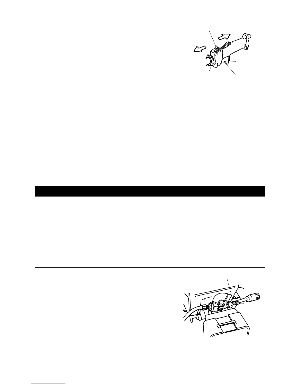
The carburetor on this engine is equipped with a fuel primer and a
choke system.
To start a “cold” engine properly, perform the following procedure:
1. Pump the primer bulb until fuel can be seen flowing through
the fuel return line to the fuel tank. Flowing fuel should be
almost clear, not foamy or full of bubbles.
2. Turn the choke lever to the Close “” position.
3. With the stop switch “ON” , and the throttle trigger positioned at
Fast-idle start position, pull the starter grip. After the engine is
started, turn the choke lever to the Open “” position. Then
squeeze and release the throttle trigger to allow it to return to the
idle position.
Gasoline two-cycle oil
1 litre 40 ml /cc
2 litre 80 ml /cc
5 litre 200 ml /cc
Primer Bulb
Fuel Return
Line
Starter grip
Choke leve
r
Close
Open
Choke lever
Page 16
- 15 -
Idle Speed Adjustment Scre
w
If the engine stops running before you turn the choke lever to the
Open “” position :
Go ahead and open the choke, pull the starter grip with the throttle
trigger positioned at Fast-idle start position.
Hot Restart
To start the engine that is already warmed up (hot restart).
1. Turn the choke lever to the open “” position, and set the stop switch to the “ON” position.
2. Leave the throttle trigger in the idle position and pull the starter grip.
3. If the engine fails to start after three to four pulls, follow the instructions in the Cold Starting Procedure
section above.
If the engine fails to start after you follow the above procedures, contact an authorized MARUYAMA dealer.
To Stop the Engine
1. Release the throttle trigger.
2. Slide the stop switch to “STOP” position.
Idle Speed Adjustment
This Multi-cutter is equipped with non-adjustable fuel mixture carburetor. The idle speed is the only
adjustment for the operator.
The attached tool may be moving during idle speed adjustment.
Wear the recommended personal protective equipment and
observe all safety instructions.
Keep hands and body away from the attached tool.
When the throttle trigger is released, the engine should return
to an idle speed. The correct speed is 2700 - 3300 min
-1
(or just
below the clutch engagement speed ). The attached tool must not
move and the engine should not stall (stop running) at engine idle
speed.
To adjust the engine idle speed, rotate the idle speed adjustment screw on the carburetor.
・
Turn the idle speed screw in (clockwise) to increase
the engine idle speed.
・
Turn the screw out (counterclockwise) to decrease
the engine idle speed.
WARNING
POTENTIAL HAZARD
・Engine must be running to make carburetor adjustments.
・When engine is running, attached tool and other parts are moving.
WHAT CAN HAPPEN
・Contact wi th moving at tached tool o r other movi n g p a r t s could cause serious personal injury
or death.
HOW TO AVOID THE HAZARD
・Keep hands, feet and clothing away from attached tool and other moving parts.
・Keep all bystanders and pets away from unit while making carburetor adjustments.
STOP(OFF
)
Stop switch
START
(ON)
Fast-idle start
position
Idle position
Fast-idle start lock
Page 17

- 16 -
If idle speed adjustment is necessary, and after adjustment the cutting attachment rotates or the
engine stalls, stop using the Multi-cutter immediately!
Contact your local authorized MARUYAMA Dealer for assistance and servicing.
Operation
MC-S(Multi-Cutter with String Trimmer Attachment)
Operating Position
Before using the Multi-Cutter with String Trimmer Attachment, check the following:
Before using the Multi-Cutter with String Trimmer Attachment, check the following:
1. The unit may be on the operator’s right side. The operator’s right
hand should be holding the shaft grip, with his or her fingers on
the throttle trigger. The right arm should be slightly bent.
2. The left hand should be holding the loop handle with the fingers
and thumb fully enclosed around the grip. The left arm should
be extended. Reposition the loop handle up or down the
driveshaft if necessary for a comfortable position.
WARNING
POTENTIAL HAZARD
・Without the shoulder hanging strap installed, the Brushcutter blade can produce side thrust
which can expose the operator and bystanders to blade contact.
・If the Multi-Cutter is not correctly positioned on the operator’s right side, the blade can produce side
thrust which can expose the operator and bystanders to blade contact.
WHAT CAN HAPPEN
・Contact with the Brushcutter blade can cause severe personal injury.
HOW TO AVOID THE HAZARD
・Never operate the Multi-Cutter without installing and using the shoulder harness/strap.
・Always operate the Multi-Cutter with the unit on your right side.
WARNING
POTENTIAL HAZARD
・Foreign objects can be thrown by the Multi-Cutter.
WHAT CAN HAPPEN
・Contact with thrown objects can cause personal injury.
HOW TO AVOID THE HAZARD
・Never operate the Multi-Cutter without the blade guard in place.
CAUTION
・Read the Safety instructions beginning on page 2 concerning proper use of the Multi-Cutter.
・Always wear gloves and protective clothing when operating the Multi-Cutter.
Shoulder Hanging Strap
Page 18

- 17 -
INCORREC
T
3. The Trimmer weight should be evenly distributed between the
arms. The trimmer head should be near and parallel to the ground.
4. Accelerate and hold the engine at cutting speed before entering the material to be cut.
5. Always release the throttle trigger and allow the engine to return to idle speed when not cutting.
6. Stop the engine when moving between work sites.
・
If the trimmer head becomes jammed, stop the engine immediately.
・
Make certain all moving parts have stopped and disconnect the
spark plug before inspecting the equipment for damage.
・
Never use a unit that has a chipped, cracked or broken trimmer head.
・
Snap the strap hook into the ring on the drive shaft. To detach
the strap quickly from the unit, pull upward on red band.
Cutting with Nylon Trimmer Line
・
The tip of the line does the cutting. The line should stay
extended while cutting.
・
Do not force the line into the material. Forcing the line
will cause it to slap against the material, increasing line
usage and causing poor cutting results.
5-10cm above
Ground
CORREC
T
WARNING
POTENTIAL HAZARD
・Use of improper line could cause line to break and be thrown in operator’s or bystander’s
direction.
WHAT CAN HAPPEN
・Use of improper line could result in serious personal injury.
HOW TO AVOID THE HAZARD
・Use only good quality, commercial grade, weld resistant trimmer line with a diameter of 2,4mm.
・Do not use any type of wire or other string-like substance. Do not use metal-reinforced line.
Stra
p
Ring
Red Band
Page 19
- 18 -
Trimming
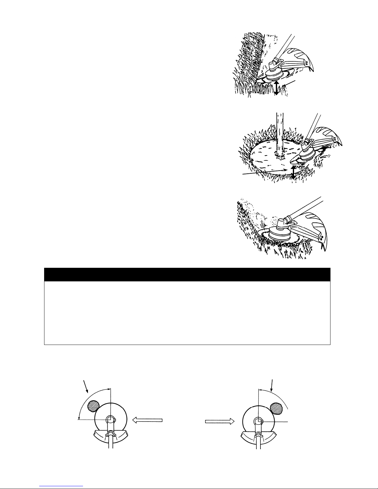
Hold the bottom of the trimmer head about 5-10cm above
the ground and at an angle. Allow only the tip of the line to
make contact.
Scaling
To remove unwanted vegetation, hold the trimmer head
about 5-10cm above the ground and at an angle. Allow the
tip of the line to strike the ground cutting the vegetation
off at the surface.
Mowing
Keep the line parallel to the ground and use a gentle
side-to-side motion.
Cutting Direction of Brushcutter Blade
When cutting heavy brush, always swing the Brushcutter from right to left. Swinging the Brushcutter from left to right
can cause the blade to kick back.
5-10cm above
Ground
5-10cm above
Ground
WARNING
POTENTIAL HAZARD
・Cutting heavy brush from the wrong direction can cause the Brushcutter blade to kick back.
WHAT CAN HAPPEN
・Contact with the Brushcutter blade can cause severe personal injury.
HOW TO AVOID THE HAZARD
・Al ways swing the Brushcutter from right to left when cutting heavy brush as shown.
CORREC
T
Direction of Swin
g
No Kic
k
-
back Zone
INCORREC
T
Direction of Swing
DANGE
R
Kick-back Zone
Page 20

- 19 -
Cutting Blades
1. Use only the correct blade (MARUYAMA genuine part) approved for the application and model Brushcutter.
2. Carefully check the condition of the blades before and after operation.
3. Sharpen dull blades. Replace any blade that is worn, cracked or damaged.
4. If a blade produces eccentric rotation or vibration, replace the blade and the boss adapter with MARUYAMA
genuine parts.
MC-E(Multi-Cutter with Edger Attachment)
Operating Position
Before using the Multi-Cutter with Edger Attachment, check the following:
1. The unit should be on the operator’s right side.
2. The operator’s right hand should be holding the shaft grip,
with his or her fingers on the throttle trigger. The right arm
should be slightly bent.
3. The left hand should be holding the loop handle with the
fingers and thumb fully enclosed around the grip. The left
arm should be extended. Reposition the loop handle up or
down the driveshaft if necessary for a comfortable position.
4. The Edger weight should be evenly distributed between the arms.
5. Adjust the Edger to the correct cutting depth before you start the engine. (Refer to Setting Depth of Cut
on this page) Make sure the blade guard is adjusted to shield the operator from thrown debris.
6. Make sure the blade is rotating (at least half throttle) before inserting the blade into the cut. The Edger
performs best at full throttle.
7. Always release the throttle trigger and allow the engine to return to idle speed when not cutting.
8. Stop the engine when moving between work sites.
Blade Guard
Direction of Travel
WARNING
POTENTIAL HAZARD
・Foreign objects can be thrown by Edger Attachment.
WHAT CAN HAPPEN
・Contact with thrown objects can cause personal injury.
HOW TO AVOID THE HAZARD
・Never operate the Edger Attachment without the blade guard in place.
・Make sure the blade guard is correctly positioned to shield operator from thrown debris.
CAUTION
・Read the Safety instructions beginning on page 2 concerning proper use of the Multi-Cutter.
Page 21

- 20 -
・
If the Edger blade becomes jammed, stop the engine immediately.
・
Make certain all moving parts have stopped and disconnect the spark plug before inspecting the
equipment for damage.
・
Never use a unit that has chipped, cracked or broken Edger blade or blade guard.
Setting Depth of Cut
IMPORTANT: Set the depth of cut before you start the
engine.
1. Loosen the knob holding the guard to the plate.
2. Rotate the guard as necessary to set the depth of cut.
Note that:
・
Rotating the guard to raise the wheel increases the depth
of cut.
・
Rotating the guard to lower the wheel decreases the depth
of cut.
3. Make sure the guard is positioned to protect the operator
from thrown debris, then tighten the knob.
MC-HT/MC-HTS(Multi-Cutter with Hedge Trimmer Attachment)
Operating Position
Before using the Multi-Cutter with Hedge Trimmer Attachment, check the following:
1. The unit should be on operator’s right side.
2. The operator’s right hand should be holding the shaft grip, with his or her fingers on the throttle trigger.
The right arm should be slightly bent.
3. The left hand should be holding the loop handle with the fingers and thumb fully enclosed around the
grip. Reposition the loop handle up or down the driveshaft if necessary for a comfortable position.
4. The Hedge Trimmer weight should be evenly distributed between the arms.
5. Make sure the cutting blades are moving (at least half throttle ) before actual cutting begins.
The Hedge Trimmer performs best at full throttle.
CAUTION
・Always wear gloves and protective clothing when operating the Multi-Cutter with Edger
Attachment.
CAUTION
・Read the Safety instructions beginning on page 2 concerning proper use of the Multi-Cutter.
CAUTION
・Do not touch the sharpened edges of the cutting blades. The cutting blades are extremely
sharp and dangerous at all times. Always wear gloves and protective clothing.
Knob
Wheel
Blade Guard
Increase the
Depth of Cut
Decrease the
Depth of Cut
Page 22

- 21 -
6. Always release the throttle trigger and allow the engine to return to speed when not cutting.
7. Stop the engine when moving between work sites.
・
If the cutting blades becomes jammed, stop the engine immediately.
・
Make certain all moving parts have stopped and disconnect the spark plug before inspecting the
equipment for damage.
・
Never use a unit that has chipped, cracked or broken blades.
IMPORTANT: The thickness of branches which may be cut using this trimmer is limited to up to
approximately 4.5mm. Never try to cut branches thicker than this, as doing so may
result in damage to the trimmer.
8. When transporting the Hedge Trimmer always fit the blade sheath.
Adjusting the angle of the blades [MC-HTS]
Note: Never use the unit if blade angle is not from 48 degree upwards to 84 degree downward.
1. First stop the engine. Next attach the blade cover.
2. Turn the clamp knob counter clockwise until the clamp knob stops.
Angle adjustments are not possible without completely loosening the clamp knob.
3 Always hold the handle when adjusting the blades. The blades adjust from a 48 degee upward angle to an 84
degree downward angle. Never push the lock lever when adjusting the angle of the blades.
4. After you have adjusted the angle of the blades tighten the clamp knob firmly and fix the gearcase in place.
When tightening the clamp knob, make sure both racks engage.
Folding procedure
1. First stop the engine. Next attach the blade cover.
2. Turn the clamp knob counter clockwise until the clamp knob stops. Folding the unit is not possible without
the clamp knob completely loosened.
3. Hold the handle securely , and then fold the blades approximately 180 degrees while pushing the lock lever to
downward. Do not touch the lock lever except when folding the blades.
4. After folding the unit, tighten the clamp knob firmly and fix the gearcase. When tightening the clamp knob make
sure that both racks are engaged.
CAUTION
・ Do not touch the sharpened edges of the cutting blades. The cutting blades are extremely
sharp and dangerous. Always wear gloves to help protect your hands and fingers from injury.
・Do not hold any part other than the handle when adjusting the angle of the blades.
・Stop the engine and set the blade cover when adjusting the angle of the blades.
Down To 84°
Clamp Knob
Handle
Blade
Cover
Lock Lever
(Push downward)
Gearcase
Up To 48°
Tighten
Loosen
Engage racks
evenly
Engaged Not Engaged
Page 23

- 22 -
MC-PS(Multi-Cutter with Pruner Attachment)
Before using the Multi-Cutter with Pruner Attachment, check the following:
1. Make sure the chain oil tank on the pruner head is full.
IMPORTANT: When filling an empty oil tank, wait approximately 60-90 seconds before starting
the Pruner. This will give the oil time to flow from the tank to the pump. Otherwise, an air lock
can occur which will prevent oil from moving through the pump. This will result in damage to
the chain and guide bar.
IMPORTANT: Never run the chain dry.
2. The unit may be on the operator’s right side. The operator’s right hand should be holding the shaft grip,
with his or her fingers on the throttle trigger. The right arm should be slightly bent.
3. The left hand should be holding the loop handle with the fingers and thumb fully enclosed around the
grip. The left arm should be extended. Reposition the loop handle up or down the driveshaft if
necessary for a comfortable position.
4. The Pruner weight should be evenly distributed between the arms.
5. Always release the throttle trigger and allow the engine to return to idle speed when not cutting.
6. Stop the engine when moving between work sites.
・
If the Pruner chain becomes jammed, stop the engine immediately.
・
Make certain all moving parts have stopped and disconnect the spark plug before inspecting the
equipment for damage.
・
Never use a unit that has a damaged chain or guide bar.
CAUTION
・Read the Safety instructions beginning on page 2 concerning proper use of the Multi-Cutter.
WARNING
POTENTIAL HAZARD
・The Pruner can conduct electricity.
WHAT CAN HAPPEN
・Contact with live electrical wires or circuits can cause serious injury or death.
HOW TO AVOID THE HAZARD
・Never use the Pruner Attachment around electrical lines, circuits or components.
CAUTION
・Always wear gloves and protective clothing when operating the Multi-Cutter with Pruner
Attachment.
Page 24

- 23 -
MC-T(Multi-Cutter with Cultivator Attachment)
Operating Position
Before using the Multi-Cutter with Cultivator Attachment, check the following:
1. The unit may be on operator’s right side. The operator’s right hand should be holding the shaft grip,
with his or her fingers on the throttle trigger. The right arm should be slightly bent.
2. The left hand should be holding the loop handle with the fingers and thumb fully enclosed around the
grip. The left arm should be extended. Reposition the loop handle up or down the driveshaft if
necessary for a comfortable position.
3. Do not operate the unit in hard un-tilled soil or in rocky areas.
4. Do not operate the unit in areas with vines or tree roots.
5. Do not operate the unit in water.
6. Always release the throttle trigger and allow the engine to return to idle speed when not cultivating.
7. Stop the engine when moving between work sites.
・
The unit should be operated only while traveling
forward. Working the unit with a back-and-forth
motion while traveling produces the best results.
A fast or slow engine speed can be used according
to soil conditions.
・
If the Cultivator tines becomes jammed, stop the engine immediately. Make certain all moving parts
have stopped and disconnect the spark plug before attempting to remove any obstruction.
・
The cultivator gearcase becomes very hot during operation. Do not touch the gearcase.
・
Make certain all moving parts have stopped and disconnect the spark plug before inspecting the
equipment for damage.
・
Never use a unit that has cracked or broken tines.
CAUTION
・Read the Safety instructions beginning on page 2 concerning proper use of the Multi-Cutter.
CAUTION
・Always wear gloves and protective clothing when operating the Multi-Cutter with Cultivator
Attachment.
Cultivator Motion
Direction of Travel
Page 25
- 24 -
Maintenance
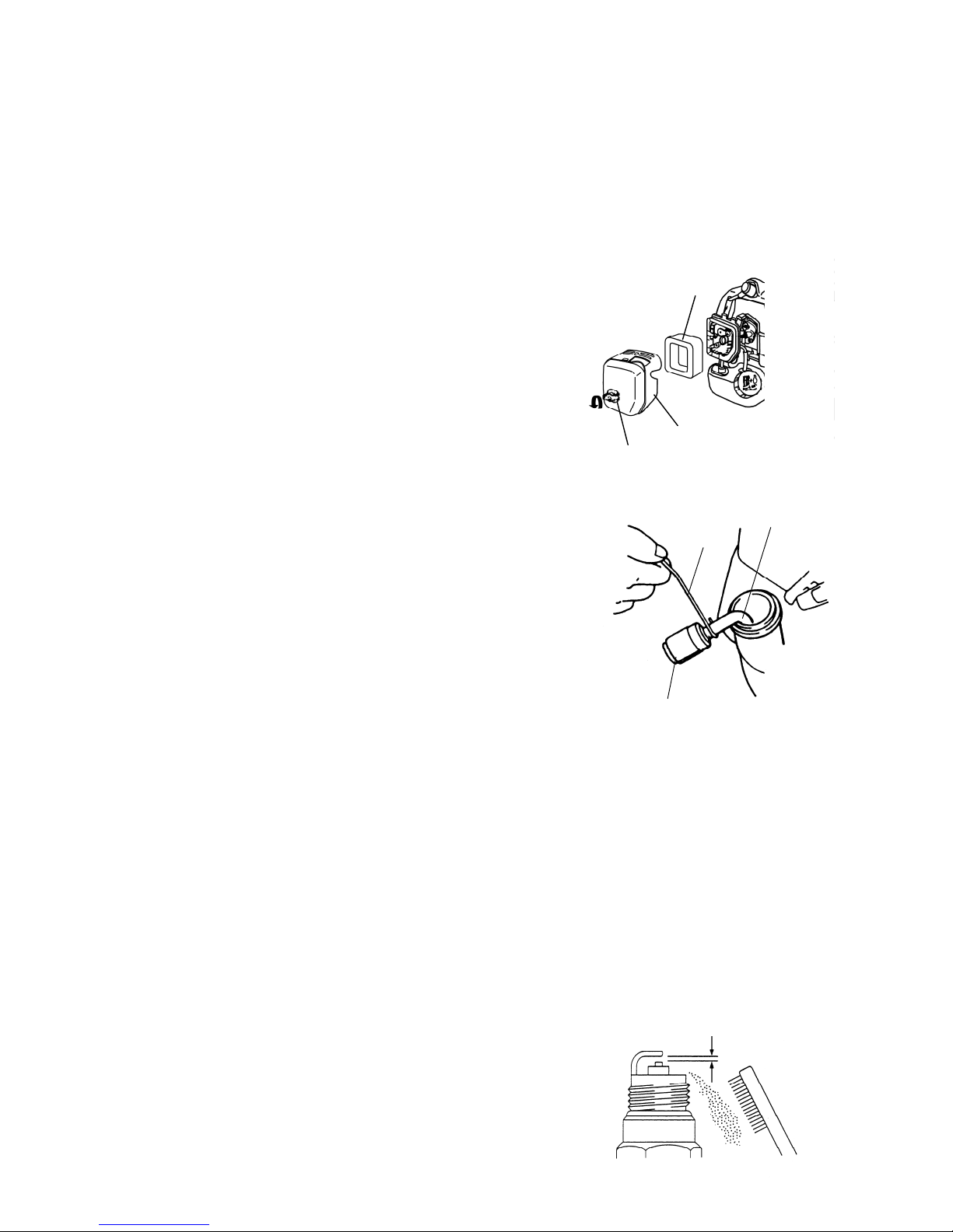
Air Filter
Maintenance Interval
・The air filter should be cleaned daily, or more often when working in extremely dusty conditions.
・Replace after every 100 hours of operation.
Air Filter Cleaning
1. Remove the foam element.
2. Clean the foam element with warm, soapy water. Let the
element dry completely.
3. Apply a light coat of SAE 30 motor oil to the foam element
and squeeze out all excess oil.
4. Reassemble the foam element and filter cover.
Fuel Filter
Maintenance Interval
The fuel filter should be replaced after every 100 hours of operation.
Fuel Filter Replacement
The fuel filter is attached to the end of the fuel pick-up hose
inside the tank. To replace the fuel filter:
1. Make sure the fuel tank is empty.
2. Remove the fuel cap.
3. Using a wire hook, gently pull the fuel filter out through the
fuel filler opening.
4. Grasp the fuel hose next to the fuel filter fitting and remove the
filter, but do not release the hose.
5. While still holding on to fuel hose, attach the new fuel filter.
6. Drop the new fuel filter back into the fuel tank.
7. Make sure that the fuel filter is not stuck in a corner of the tank,
and that the fuel hose is not doubled over (kinked) before refueling.
Spark Plug
Maintenance Interval
・The spark plug should be removed from the engine and checked after each 25 hours of operation.
・
Replace
the spark plug after every 100 hours of operation.
Spark Plug Maintenance
1. Twist the high tension lead boot on the spark plug back and forth a couple of times to loosen the boot,
then pull the boot off of the spark plug.
2. Remove the spark plug.
3. Clean the electrodes with a stiff brush.
4. Adjust the electrode air gap to 0.6-0.7 mm.
5. Replace the spark plug if it is oil-fouled, damaged, or if the
electrodes are worn down.
6. Do not over tighten the spark plug when installing.
The tightening torque is 10.7-16.6 N·m.
0.6 - 0.7mm
Fuel Pic
k
-up
Hose
Wire
Fuel Filte
r
Foam Element
Filter Cover
Knob
Page 26
- 25 -
Cylinder Cooling Fins
Maintenance Interval
・The cylinder cooling fins should be cleaned after every 25
hours
of operation, or once a week, whichever comes first.
・
Air must flow freely around and through the cylinder cooling fins to
prevent engine overheating. Leaves, grass, dirt and debris buildup
on the fins will increase the operating temperature of the engine,
which can reduce engine performance and shorten engine life.
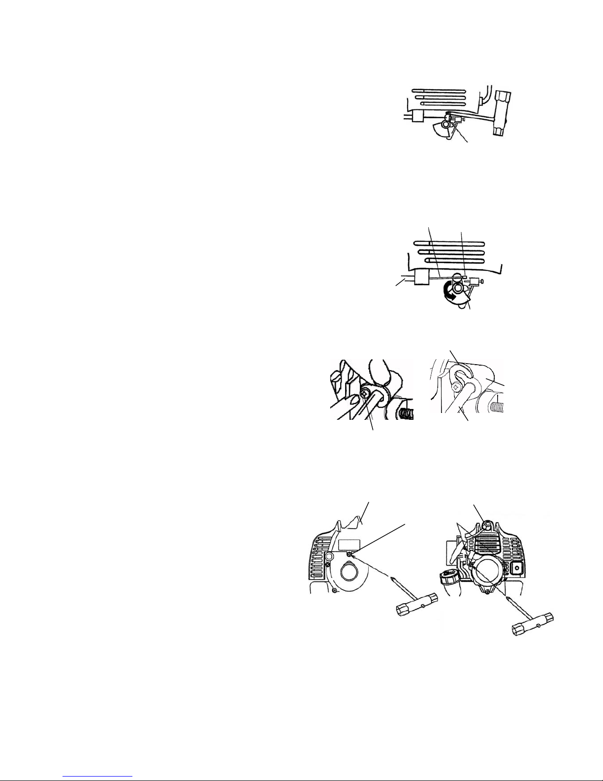
Cooling Fin Cleaning
Note: It's necessary to remove the swivel ring before
detouch the cylinder cover.
1. Press up the bottom of the swivel ring to remove the
swivel ring. Note: Take care of falling the swivel ring in
the engine when remove the swivel ring.
2. Rotate the carburetor throttle cam and slip out the throttle
cable tab from the slot in the slotted fitting.
3. Loosen the screw. Turn up the hook, then pull out the
throttle cable housing from the guide.
4. Twist the high tension lead boot on the spark plug
back and forth a couple of times to loosen the boot,
then pull the boot off of the spark plug.
5. Remove three screws and lift off the cylinder cover.
6. Clean all dirt and debris from the cooling fins and
from around the cylinder base.
7. After cleaning, reinstall the cylinder cover and
the high tention lead boot. Then reinstall the throttle
wire, hook, throttle cable end and swivel ring in order.
Screw
Three Screws
Cylinder Cover
High Tension
Lead Boo
t
Throttle Cable
Housing
Guide
Hook
Swivel Ring
Throttle Cable
Throttle
Cable Tab
Carburetor
Throttle Cam
Throttle Cable
Housing
Page 27

- 26 -
Spark Arrester
Maintenance Interval
・The spark arrester should be inspected and cleaned after every 25 hours
of operation.
Replace the screen if it cannot be thoroughly cleaned or if it is damage.
Maintenance
・
The spark arrester is installed inside the exhaust outlet of the muffler.
One screw and washer located on the side of the exhaust outlet holds
the spark arrester in place.
1. Remove the cylinder cover. (See section “
Cylinder Cooling Fins”)
2. Remove spark arrester retaining screw, then using a suitable pair
of pliers, withdraw the spark arrester. Do not crush or distort the
spark arrester flange during removal.
3.
The screen can be cleaned using a non-flammable solvent and a stiff
wire brush. To reinstall insert the spark arrester into the exhaust
outlet while aligning the holes in the arrester flange and outlet
for the retaining screw.
4. Rei
nstall the screw and washer, then reinstall the cylinder cover.
MC-S(String Trimmer Attachment)
Gearcase
Maintenance Interval
The gearcase should be checked for lubrication after each 30
hours of use.
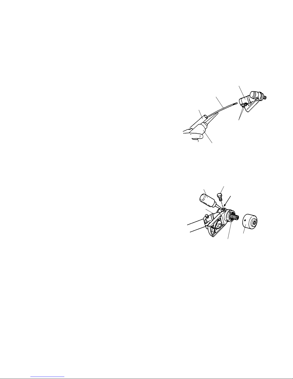
Gearcase Lubrication
Remove the cutting attachment and the boss adapter. Clean any
dirt and debris from the area between the boss adapter and the
gearcase. Remove the grease plug from the side of the gearcase.
While rotating the attaching shaft, inject lithium-base bearing lube
(P/N 211337) through the plug hole until the gearcase is full.
Reinstall the boss adapter and grease plug.
WARNING
POTENTIAL HAZARD
・Muffler surface becomes hot when Trimmer/Brushcutter is in operation and remains hot for
sometime after the engine is shut off.
WHAT CAN HAPPEN
・Contact with hot muffler surface could cause a burn.
HOW TO AVOID THE HAZARD
・Make sure the muffler is cool before inspecting and cleaning the spark arrester.
Spark Arreste
r
Scre
w
Washe
r
Muffler Bod
y
Attaching Shaft
Grease Plug
Plug Hole
Boss Ada
pter
Gearcase
Bearing Lube
(P/N.211337)
Page 28
- 27 -
MC-E(Edger Attachment)
Flexible Drive Shaft
Maintenance Interval
The Edger Attachment uses a flexible drive shaft inside the drive
shaft tube. The flexible drive shaft should be lubricated after
each 30 hours of use.
Flexible Drive Shaft Lubrication
1. Loosen the two screws holding the gearcase to the drive shaft tube
and carefully remove the gearcase from the drive shaft tube.
2. Grip the end of the flexible drive shaft and remove it from the
drive shaft tube.
3. Lubricate the flexible drive shaft with a high quality #2
lithium-base bearing lube.
4. Reinstall the flexible drive shaft into the drive shaft tube.
Twist the flexible drive shaft as you insert it into the to ensure
that it seats into the clutch drum.
5. Reinstall the gearcase onto the drive shaft tube, then tighten
the two screws.
Gearcase
Maintenance Interval
The gearcase lubricant should be inspected for after every 30
hours of use.
Gearcase Maintenance
Remove the blade and the boss adapter. Clean any dirt and
debris from the area between the boss adapter and the
gearcase. Remove the gearcase plug from the side of the
gearcase. While rotating the attaching shaft, inject lithium-base
bearing lube (P/N 211337) through the plug hole until the
gearcase is full. Re-install the gearcase plug.
Attaching Shaf
t
Grease Plug
Plug Hole
Boss Adapte
r
Gearcase
Bearing Lube
(P/N.211337)
Flexible Shaft
Driveshaft Tube
Scre
w
Gearcase
#2 Lithium
-
Base Bearing Lube
Page 29

- 28 -
MC-HT/MC-HTS(Hedge Trimmer Attachment)
Adjusting Cutting Blades
Maintenance Interval
Before operating the Multi-Cutter with Hedge Trimmer Attachment it is necessary to check the adjustment
of the cutting blades. Blades that are too loose may vibrate, and will not provide a clean, smooth cut.
Cutting Blades Maintenance
CAUTION-BLADES THAT ARE TOO TIGHT CAN CAUSE OVERLOADING WHICH MAY DAMAGE
THE EQUIPMENT.
To adjust the cutting blades, refer to the illustrations and locate
the tension screws.
Loosen the tension screw lock nuts. Gently turn the tension
screws in until sung, then turn the tension screws back out the
lock nuts. Liberally coat the cutting blades with light oil. Start
the engine and operate the Multi-Cutter with Hedge Trimmer
Attachment at full speed for at least one minute. Stop the
engine, and when the blades are motionless, touch the blades
with your hand.
The blades may be warm, but if they are too hot to touch,
loosen the tension screws 1/8 turn.
Lubrication
Maintenance Interval
・The gearcase and angle drive should be inspect after each 10 to 20 hours of use.
・Cutting blades should be lubricated at all times.
Lubrication
The gearcase and angle drive should be checked for lubrication
after each 10 to 20 hours of use. Grease fittings are installed
into both components. Use #2 lithium-base bearing lubricant.
Lubrication of the cutting blades should be maintained at all
times. Use a light oil (#10wt.).
CAUTION
・Do not touch the sharpened edges of the cutting blades. The cutting blades are extremely
sharp and dangerous at all times.
Flat Washer
Tension Scre
w
Guide Ba
r
Lock
nu
t
U
pper Blade
L
ower Blade
Lock
nut
Tension Screw
Light Oil (# 10wt.)
Grease Fitting
for Angle Drive
Grease Fitting
for Gearcase
Cutting Blade
[MC-HT]
Light Oil
(#10wt.)
Cutting Blade
Grease Fitting
Grease Fitting
[MC-HTS]
Page 30
- 29 -
MC-T(Cultivator Attachment)
Lubrication
Maintenance Interval
The Cultivator gearcase should be inspect after each 25 hours of use.
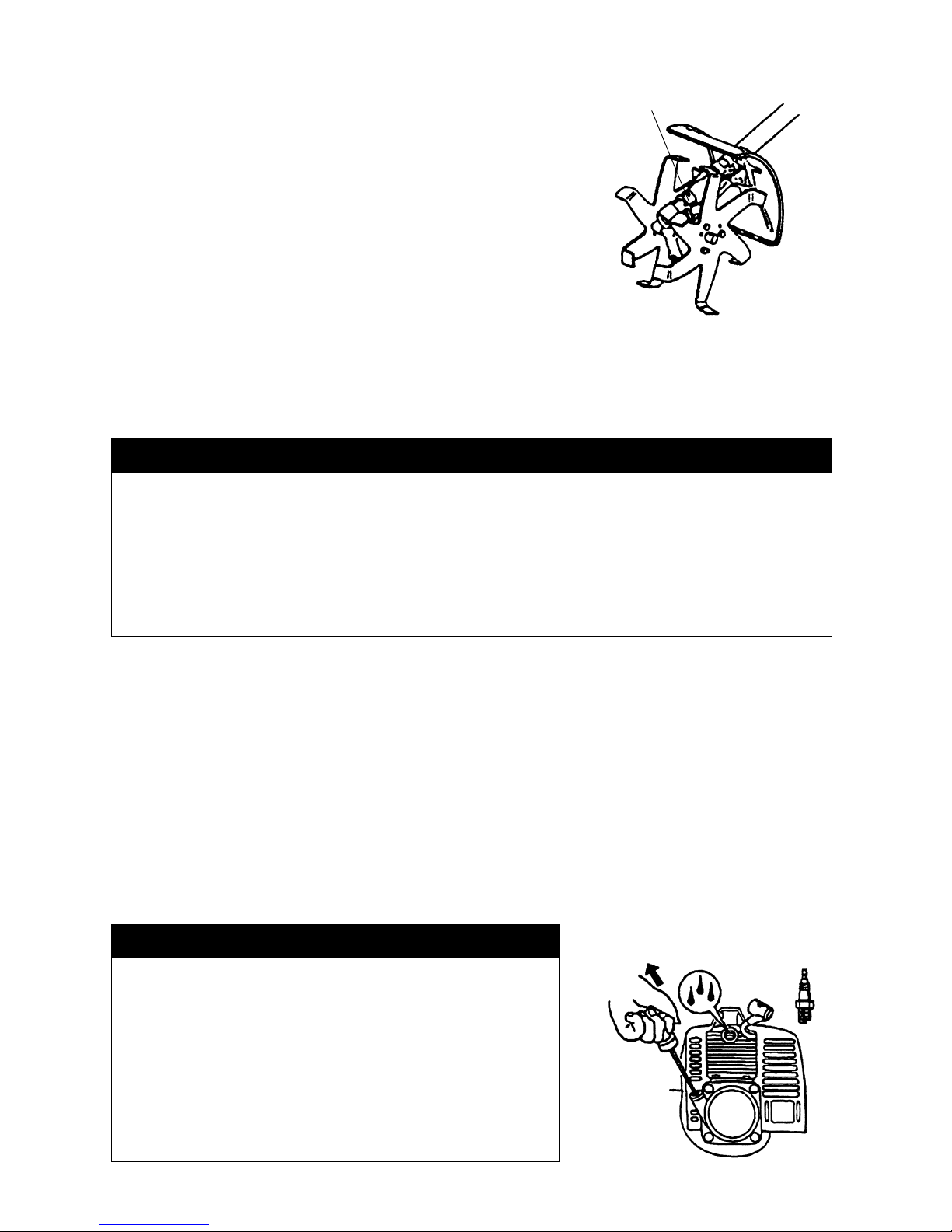
Lubrication
The Cultivator gearcase holds 40g of lubricant. A grease fitting is
located in the top of the gearcase. Lubricant should be checked at
least every 25 hours of operation. Use a#2 lithium-based
lubricant with Molybdenum additive.
General Cleaning and Tightening
The MARUYAMA Multi-Cutter will provide maximum performance for many, many hours if it is maintained
properly. Good maintenance includes regular checking of all fasteners for correct tightness, and cleaning
the entire machine.
Storage
For long term storage of the Multi-Cutter:
1. Empty the fuel tank into a suitable fuel storage container.
2. Run the engine to remove any fuel that may remain in the carburetor.
3. Perform all regular maintenance procedures and any needed repairs.
4. Remove the spark plug and squirt a very small amount of engine oil into the cylinder.
WARNING
POTENTIAL HAZARD
・When engine is running, attached tool and other parts are moving.
WHAT CAN HAPPEN
・Contact wi th moving to ol or other m o v i n g p a r t s could cause serious personal injury or death.
HOW TO AVOID THE HAZARD
・Always turn off your Multi-Cutter before you clean or perform any maintenance on it.
CAUTION
POTENTIAL HAZARD
・Oil may squirt out of the spark plug opening when you
pull the starter grip.
WHAT CAN HAPPEN
・Oil can cause eye injuries.
HOW TO AVOID THE HAZARD
・Protect your eyes and keep your face away from the
spark plug opening.
Grease Fitting
for Gearcase
Page 31

- 30 -
5. Pull the starter grip once.
6. Reinstall the spark plug.7. Store the Multi-Cutter in a dry place away from excessive heat, sparks or open
flame.
Troubleshooting
Problem Cause Action
Engine will not start
・STOP switch set to off position
・Empty fuel tank
・Primer bulb wasn’t pushed enough
・Engine flooded
・Move switch to on position
・Fill fuel tank
・Press primer bulb until fuel flows
through fuel return line
・Use warm engine starting procedure
Engine will not Idle
・Idle speed set incorrectly ・Set Idle speed
Engine lacks power or
stalls when cutting
・Throttle wire has come loose
・Dirty air filter
・Tighten throttle wire
・Clean or replace air filter
If further assistance is required, contact your local authorized MARUYAMA service dealer.
Specifications
MC2600RS With
MC-S MC-E MC-HT MC-HTS MC-PS MC-T
Weight ※1
5,0 kg 5,6 kg 6,5 kg 6,6 kg 6,0 kg 6,8 kg
Engine Displacement 25,4 cm3
Fuel Tank Capacity 0,6 litre
Carburetor Diaphragm Type
Ignition System Solid State
Spark Plug NGK BPMR6Y
Fuel Mixture Two cycle Oil Mix 25:1 Ratio
※1. Dry weight without Cutting Attachment, harness and fuel.
Page 32

- 31 -
P/N.231082-00 GB 0908 TAP/DP
Manufacturing:
Maruyama Mfg. Co., Inc. 4-15 Uchi-kanda 3-Chome,
Chiyoda-ku Tokyo 101-0047 Japan
Tel. 03-3252-2281
 Loading...