

Page 1
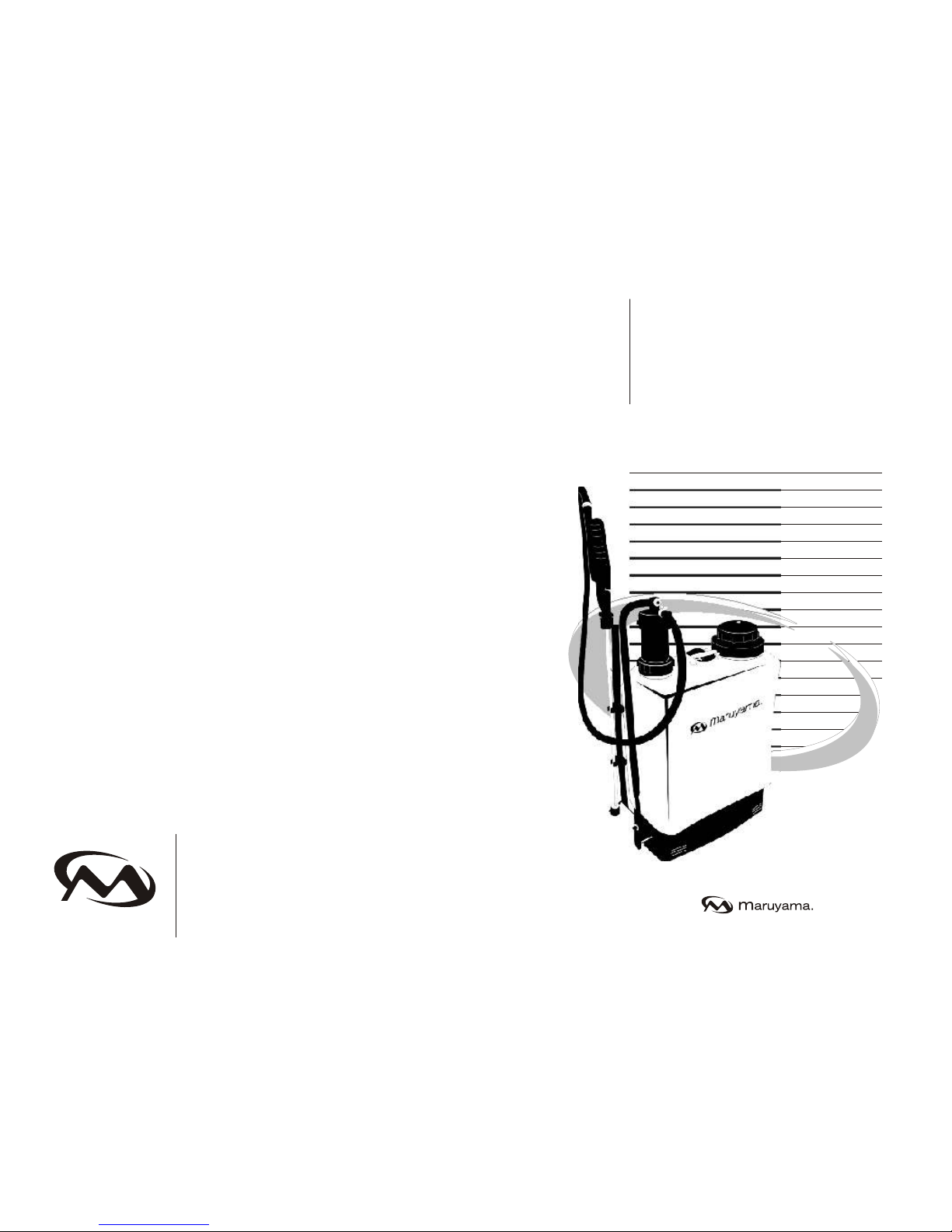
OPERATOR’S MANUAL
BACKPACK SPRAYER
M409
MARUYAMA
Maruyama U.S. Inc.
Post Office Box 309
Auburn, WA 98071-0309
253-735-7368 voice
253-735-1416 fax
www.maruyama-us.com
Premium Outdoor Power Equipment Extraordinary
Completely read and understand this manual prior to using this product.
Page 2
Maruyama is grateful to you for purchasing this product.
Prior to operating the sprayer, please read this owner’s
manual to obtain the best results.
GENERAL INDEX
Technical specifications ............................................................
Assembly Instructions... ...........................................................
Back pack sprayer calibration ..................................................
Chemical mixing procedure ......................................................
Maintenance ............................................................................
Troubleshooting guide .............................................................
Pressure chamber components ..............................................
Brass cylinder components .....................................................
Back Pack Sprayer components .............................................
Trigger valve components .......................................................
1
2
2
3
3
4
5
5
6
8
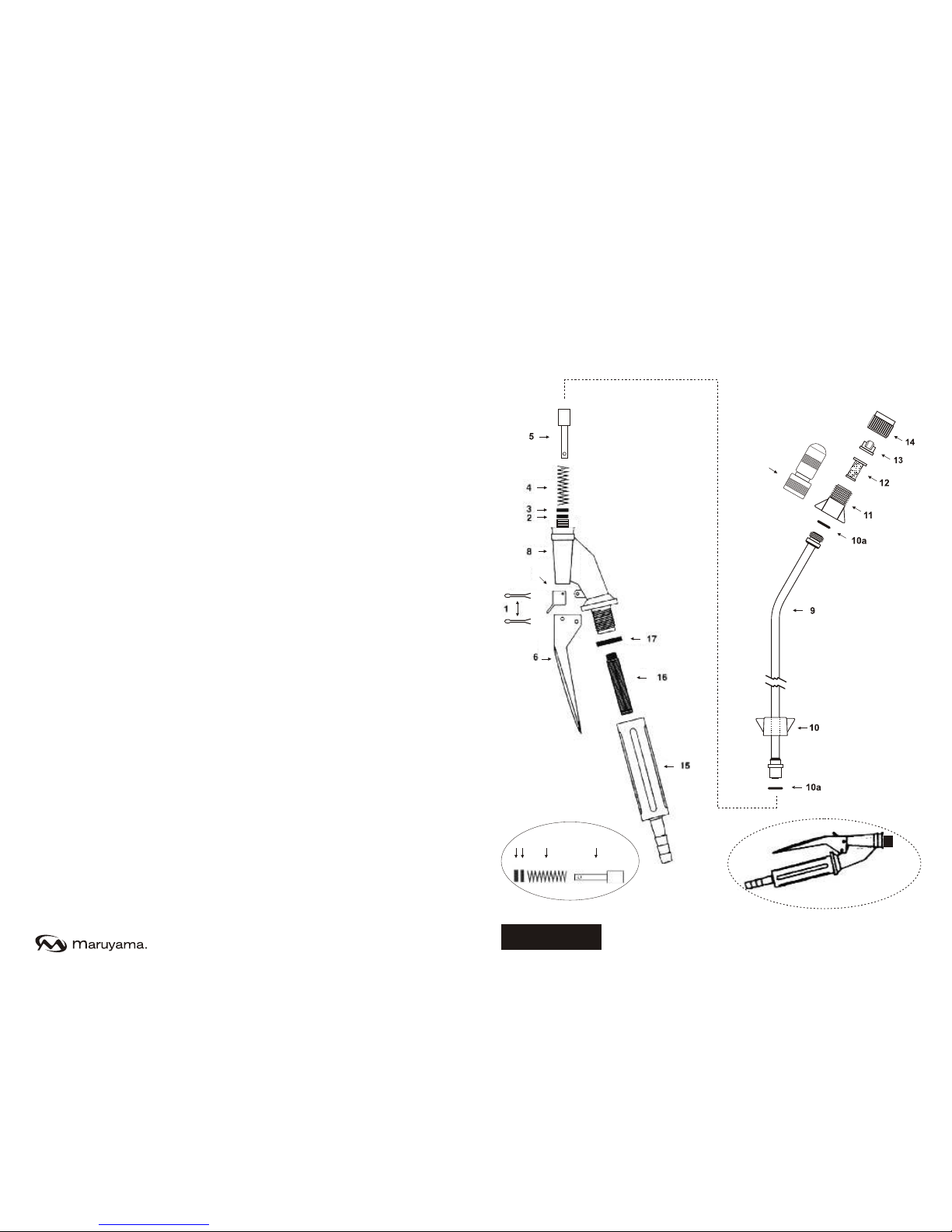
TRIGGER VALVE COMPONENTS
ENGLISH
9
18
7
2 3 4 5
19
20
Page 3
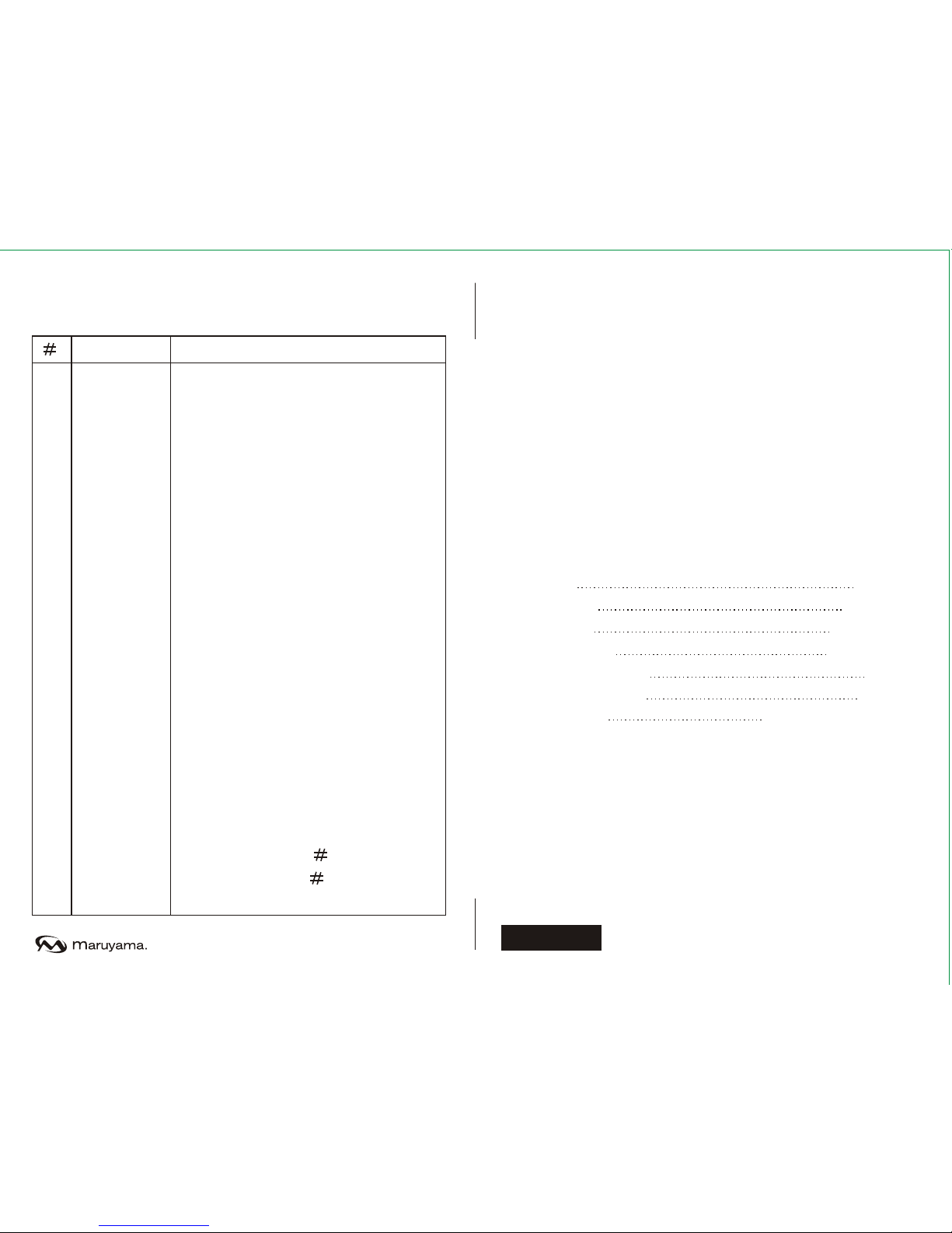
Description
Clamps (2)
Viton O´ring
Brass circle stopped seal
Piston trigger lance spring
Piston trigger lance
Trigger - lever
Fastener hook
Body valve
Spare pipe for lance (20 inches) nozzle
Tip nut
O´ring 5081 (2)
Body tip
Tip filter
Flat fan tip VP 02 F110
Tip cap
Lance handle
Lance filter
Lance handle seal (viton)
Adjustable brass nozzle
Piston lance assy ( 2, 3, 4, 5)
Lance body assy ( 2, 3, 4, 5,6, 7, 8,
9, 10, 11, 12, 13, 14, 15, 16, 17)
OPERATING INSTRUCTIONS
In this manual you will find all the instructions you need to operate
your sprayer properly.
TECHNICAL SPECIFICATIONS
Model M409
Net weight:
Tank Capacity:
Tank Material:
Working pressure
Standard lance length:
Standard hose length:
Provided nozzle:
8,75 Lbs.
4,2 Gallons
Polyethylene
30 to 90 p.s.i.
1,64 feet
3,77 feet
Adjustable brass nozzle
Flat fan nozzle
1
2
3
4
5
6
7
8
9
10
10a
11
12
13
14
15
16
17
18
19
20
Code
840661
840662
840663
840664
840665
840666
840667
840668
840669
840670
840600
840671
840672
840673
840674
840675
840676
840677
840692
840697
840698
TRIGGER VALVE COMPONENTS
ENGLISH
18
Page 4
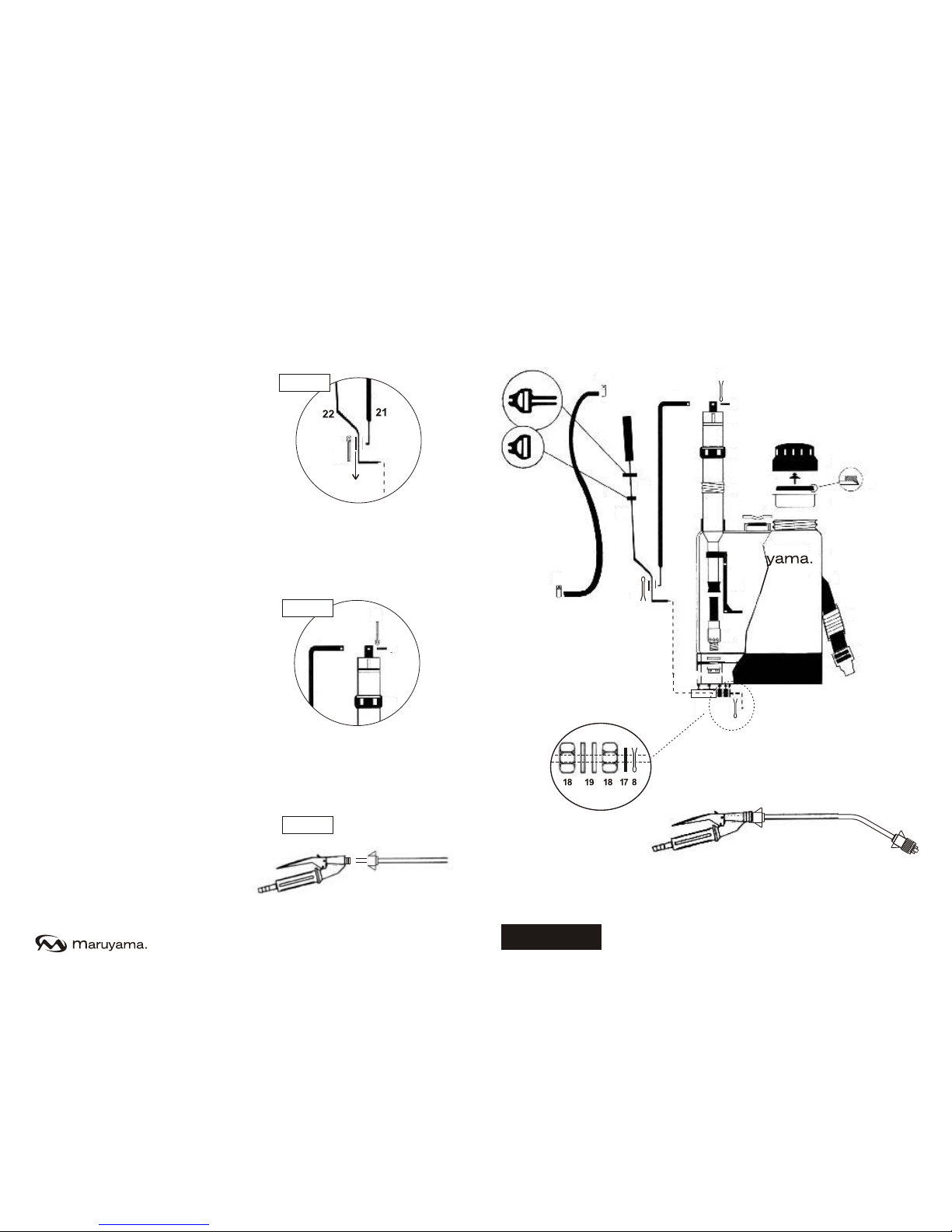
BACK PACK SPRAYER COMPONENTS
ASSEMBLY INSTRUCTIONS
You will find your Sprayer
assembled and ready to be
operated, less the hose,
which is separate from the
lance and the sprayer
pump. Connect the hose to
the outlet pump connector
and to the lance, and adjust
both ends with the two hose
clamps you will find inside
the strainer in the sprayer
cap.
The straps are padded and
provided with adjusting
buckles.
The correct operating
position is when the top of
the tank is on the same level
as the operator neck.
To assemble spraying
lance, press the trigger
lever (nº 6) and tighten the
plastic tip nut (nº 10) to the
bronze lance pipe. Lastly,
release the lever.
(Important: Never tighten
tip nut without pressing on
the trigger lever.)
ENGLISH
72
6
10
fig. 3
20
16
15
M409
23
23
24
22
26
8
30
21
8
9
10
11
12
13
14
15
16
17
8
20
27
28
1
29
2
3
4
5
6
7
25
fig. 2
30
fig. 1
8
9
10
11
21
8
30
Page 5
1
2
3
4
5
6
7
8
9
10
11
12
13
14
15
16
17
18
19
20
21
22
23
24
25
26
27
28
29
30
Code
840727
840579
840580
840581
840582
840583
840584
840585
840586
840587
840588
840589
840590
840591
840592
840593
840594
840595
840660
840596
840597
840598
840599
840619
840620
840621
840622
840623
840624
840625
Description
Fill cap
Strainer
Tank (4.2 gallons)
Strap
Strap padding kit (2 units)
Buckle kit (2 units)
Plastic base
Pin (3 units)
Joining bolt to the chamber
Pressure chamber (assambly)
Chamber guide nut
Pressure chamber seal
Agitator assembly
Brass cylinder (assemblyt)
Brass cylinder gasket seal
Brass cylinder nut
Lever guide ring
Lever guide brass nut (2)
Lever
Lever guide pipe
Lever arm
Lever
Hole clamp
Hose
Trigger valve lance (flat fan tip)
Lance and lever arm support kit
Strap fastener
Backpack cap valve
Backpack cap seal
Lever arm ring
BACK PACK SPRAYER COMPONENTS
CHEMICAL MIXING
PROCEDURE
a) Fill bucket with 1.3 gallons of
clear water and add the chemical.
b) Shake well until the mixture
looks homogeneous.
c) Place this liquid inside the spray
tank and fill desired amount of
water.
d) Spray mixture immediately after
you have filled the tank.
MAINTENANCE
When you have finished using the
sprayer, wash the tank well with
clear water and some detergent if
possible. Operate the sprayer with
water to wash the pump and the
trigger valve. Rinse it, dry it and
store it in a clear place.
IMPORT ANT !
Never store the sprayer with
chemical remains. It can
temporarily or permanently
damage your equipment.
ENGLISH
36
SPRAYER
CALIBRATION
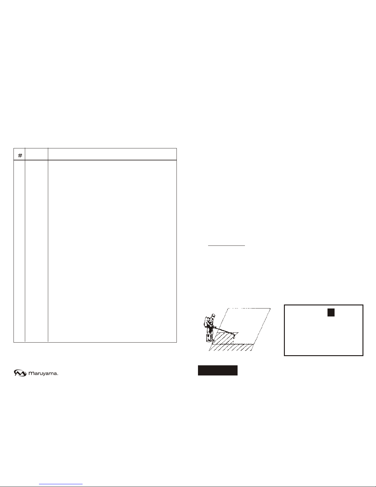
a) Mark a field area of 328 ft (square
of 32.8 x 32.8 sq or 328 sq ft x 3.28 ft)
b) Fill the tank with clear water and
apply over the marked area keeping
a constant pumping and walking
rhythm.
c) Calculate the flow rate in gallons by
hectare using the following formula:
Q = Flow rate in gallons
32800= ft correspond with 1 hectare
A = Applied area (328 ft )
Vol. x 32800 ft
A=328 ft
d) If the flow rate is not in accordance
with your needs, change to a larger or
smaller nozzle according to the
results.
=
Q
2
2
2
2
2
32.8 ft
32.8 ft
Page 6
TROUBLESHOOTING GUIDE
Place approximately 5 gallons of water in the tank. Operate the pump,
and watch inside the tank to identify the problem according to the
following table:
Problem
The liquid is coming out
from the upside of the brass
cylinder.
When pumping and filling
the chamber the liquid
returns back through the
admission and the chamber
falls down quickly.
When pumping and filling
the chamber and releasing
the action lever; the
chamber ascends.
Cause
The piston seal is
worn out.
Brass cylinder valve
won’t shut due to
wear or dirt.
Chamber valve wear
Solution
Change the piston
seal.
Clean or change the
cylinder valve.
Clean or change the
chamber valve.
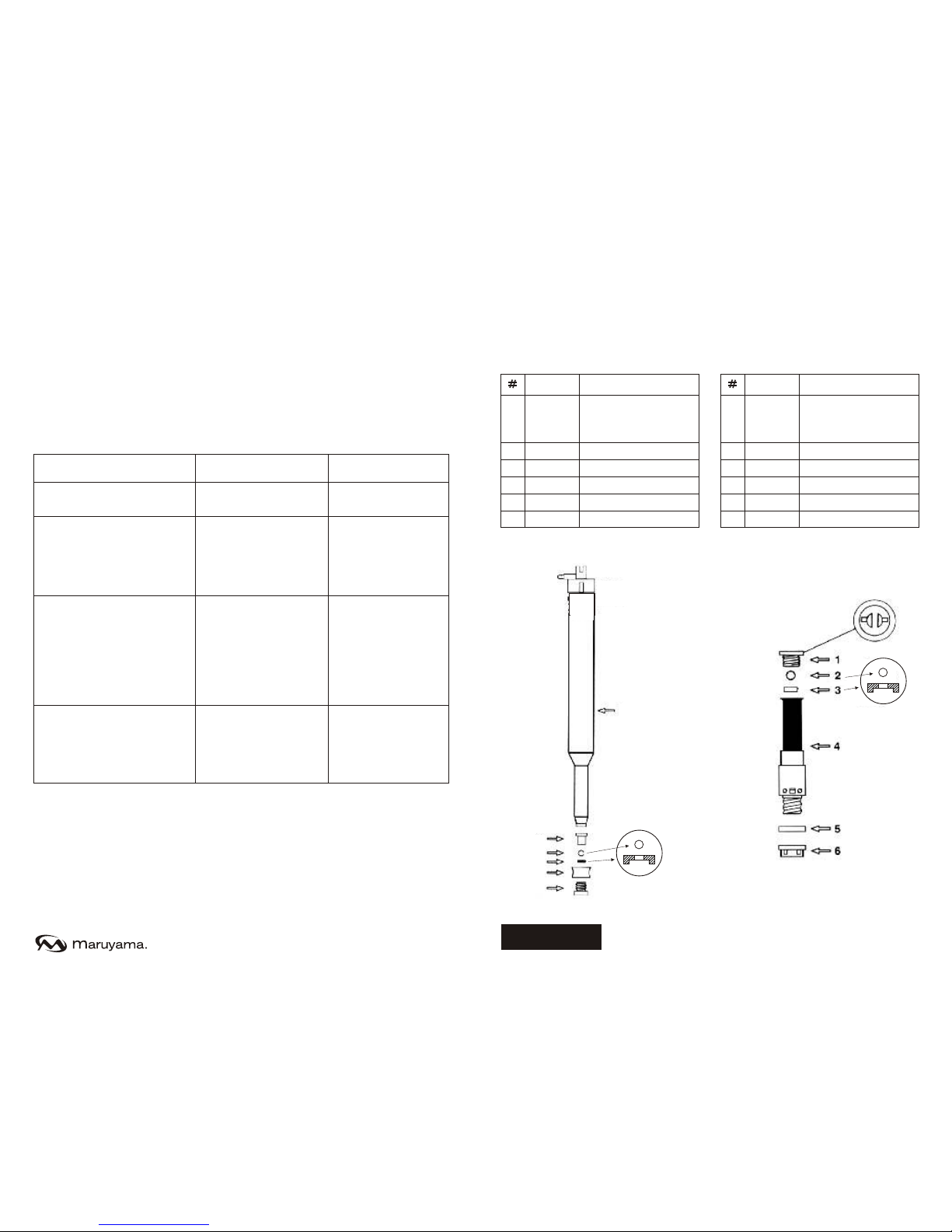
BRASS CYLINDER
COMPONENTS
Code
840680
840681
840682
840683
840739
840685
Description
Pressure Chamber
(no valve box or seal)
Chamber valve cap
Valve
Valve seal (viton)
Double piston seal
Valve box
1
2
3
4
5
6
PRESSURE CHAMBER
COMPONENTS
1
2
3
4
5
6
ENGLISH
5
4
Code
840686
840682
840683
840689
840592
840593
Description
Brass cylinder valve
cap
Valve
Valve seal (viton)
Cylinder only
Brass cylinder seal
Brass cylinder nut
1
2
3
4
5
6
 Loading...