

Page 1

Page 2

English
Limited Warranty Statement
All Maruyama commercial/ industrial products are warranted to the original purchaser to be free from defects
in material and workmanship from the date of purchase for the time periods listed as follows:
Lifetime for solid steel driveshaft and ignition coils.
5 years for qualified IRON 5-YR™ commercial, institutional, or industrial use.
1 year for residential or 2 years for commercial use with competitor’s oil.
90 days for rental use.
Engine - Refer to engine manufacturer’s warranty statement. Only Maruyama engines are
covered by this limited warranty statement.
Any part of a Maruyama product found to be defective within the applicable warranty period shall, at
Maruyama's option, be repaired or replaced without charge. Warranty consideration is obtained by delivering any Maruyama product believed to be defective to an Authorized Maruyama Servicing Dealer within the
applicable warranty period.
The purchaser shall not be charged for diagnostic labor that leads to the determination that a warranted part
is defective, if the diagnostic work is performed at a Maruyama Dealer.
Any warranted part which is not scheduled for replacement as required maintenance, or which is scheduled
only for regular inspection to the effect of "repair or replace as necessary" shall be warranted for the warranty
period. Any warranted part, which is scheduled for replacement as, required maintenance shall be warranted
for the period of time up to the first scheduled replacement point for that part. Maruyama Mfg. Co., Inc. is liable for damages to other engine components caused by the failure of a warranted part still under warranty.
The purchaser is responsible for the performance of the required maintenance, as defined by Maruyama
Mfg. Co., Inc. in the Owner's/Operator's Manual.
EMISSION-RELATED PARTS WARRANTY: In addition to the above warranty coverage, Maruyama Mfg.
Co., Inc. will repair or replace, free of charge, for the original purchaser and each subsequent purchaser any
emission-related part or parts found to be defective in material and workmanship for two (2) years from original retail delivery date except catalytic converter. Catalytic converter is warranted one year from origi-
nal retail delivery date. Emission-related parts are the carburetor assembly, the ignition coil
assembly, the ignition rotor and the spark plug and catalytic converter. Any replacement part that is
equivalent in performance and durability may be used in non-warranty maintenance or repairs, and shall not
reduce the warranty obligations of Maruyama Mfg. Co., Inc.
Effective June 1, 2000
| 1 |
Page 3

English
This warranty does not cover the following:
1. Maintenance items (excluding defects in materials and workmanship) including hoses, spark plugs,
starter rope, air and fuel filters, clutch shoes, vibration isolators, throttle cables and all cutting attachments, etc.
2. Extra expenses including shipping and handling, travel, payment for lost time or pay and for any inconvenience and storage.
3. Alterations or modifications including aftermarket parts not authorized by Maruyama U.S., Inc.
4. Wear, accident, abuse, neglect, misuse, negligence, improper fuels, lubricants, fuel mixtures (when applicable), or failure to operate or maintain the product in accordance with instructions approved by
Maruyama.
Repair or replacement as provided under this warranty is the exclusive remedy of the consumer. Maruyama
shall not be liable for any incidental or consequential damages for breach of any express or implied warranty
on these products except to the extent prohibited by applicable law. Any implied warranty of merchantability
or fitness for a particular purpose on these products is limited in duration to the warranty period as defined in
the limited warranty statement. Maruyama reserves the rights to change or improve the design of the product without notice and does not assume obligation to update previously manufactured products.
This warranty provides you with specific legal rights, which may vary from state to state.
It is the Owner's and Dealer's responsibility to make sure the Warranty Registration Card is properly filled out
and mailed to Maruyama U.S., Inc. Proof of purchase and registration will be required in order to obtain warranty service.
To locate an Authorized Maruyama Servicing Dealer nearest you, contact:
Maruyama U.S., Inc.
4770 Mercantile Drive, suite 100,
Fort Worth, TX 76137
(940) 383-7400
www.maruyama-us.com
.
Effective June 1, 2000
| 2 |
Page 4
English
WARNING
2
0
4
6
8
10
THE AIR INDEX OF THIS ENGINE IS 3
MOST CLEAN
NOTE:THE LOWER THE AIR INDEX, THE LESS POLLUTION
THIS ENGINE IS CERTIFIED TO BE EMISSIONS
COMPLIANT FOR THE USE:EXTENDED: 300HOURS
CHECK THE OWNER'S MANUAL FOR FURTHER DETAILS
LEAST CLEAN
.
.
The engine exhaust from this product
contains chemicals known to the State
of California to cause cancer, birth
defects or other reproductive harm.
:
CER230HT
FEDERAL EMISSION CONTROL WARRANTY STATEMENT
YOUR WARRANTY RIGHTS AND OBLIGATIONS
The U.S. Environmental Protection Agency (EPA) and Maruyama Manufacturing Company, Inc.
are pleased to explain the emission control system warranty on your small off-road engine. New
1997 and later model year small off-road engines must be designed, built and equipped, at the
time of sale, to meet the U.S. EPA regulations for small off-road engines. The equipment engine
must be free from defects in materials and workmanship which cause it to fail to conform with U.S.
EPA standards for the first two years of engine use from the date of sale to the ultimate purchaser.
Maruyama Manufacturing Company, Inc. must warrant the emission control system on your small
off-road engine for the period of time listed above provided there has been no abuse, neglect or
improper maintenance of your small off-road engine.
Emission durability of 300 hours.
Your emission control system may include parts such as the carburetor or fuel injection system,
the ignition system, and catalytic converter. Also included may be hoses, belts, and connectors
and other emission related assemblies.
Where a warrantable condition exists, Maruyama Manufacturing Company, Inc. will repair your
small off-road engine at no cost to you, including diagnosis (if the diagnostic work is performed
at an authorized dealer), parts, and labor.
MANUFACTURER'S WARRANTY COVERAGE:
The 1997 and later model year small off-road engines are warranted for two years. If any
emission-related part on your engine is defective, the part will be repaired or replaced by
Maruyama Manufacturing Company, Inc. free of charge.
| 3 |
Page 5
Introduction
Thank you for purchasing a MARUYAMA product.
MARUYAMA, it’s distributors, and dealers want you
to be completely satisfied with your new product.
Please feel free to contact your local Authorized
Service Dealer for help with service, genuine
MARUYAMA parts, or other information you may
require.
Whenever you contact your Authorized Service Dealer
or the factory, always know the serial number of your
product. This number will help the Service Dealer or
Service Representative provide exact information about
your specific product. You will find the model and
serial number located in a unique place on the product
(Product Description on page US-7).
For your convenience, write the product model name
and serial number in the space below.
DANGER signals an extreme hazard that will cause
serious injury or death if the recommended precautions
are not followed.
WAR NI NG
or death if the recommended precautions are not followed.
CAUTION signals a hazard that may cause minor or
moderate injury if the recommended precautions are
not followed. Two other words are also used to highlight information. “Important” calls attention to special
mechanical information and “Note” emphasizes general information worthy of special attention.
signals a hazard that may cause serious injury
Safety
Operator Safety
1. Read and understand this Owner’s/Operator’s
Manual before using this product. Be thoroughly
familiar with the proper use of this product.
Model Name
Serial No.
Read this manual carefully to learn how to operate and
maintain your product correctly. Reading this manual
will help you and others avoid personal injury and
damage to the product.
Although MARUYAMA designs, produces and markets safe, state-of-the-art products, you are responsible
for using the product properly and safely. You are also
responsible for training persons who you allow to use
the product about safe operation.
The MARUYAMA warning system in this manual
identifies potential hazards and has special safety messages that help you and others avoid personal injury,
even death.
DANGER, WARNING and CAUTION are signal
words used to identify the level of hazard. However,
regardless of the hazard, be extremely careful.
_______________
________________
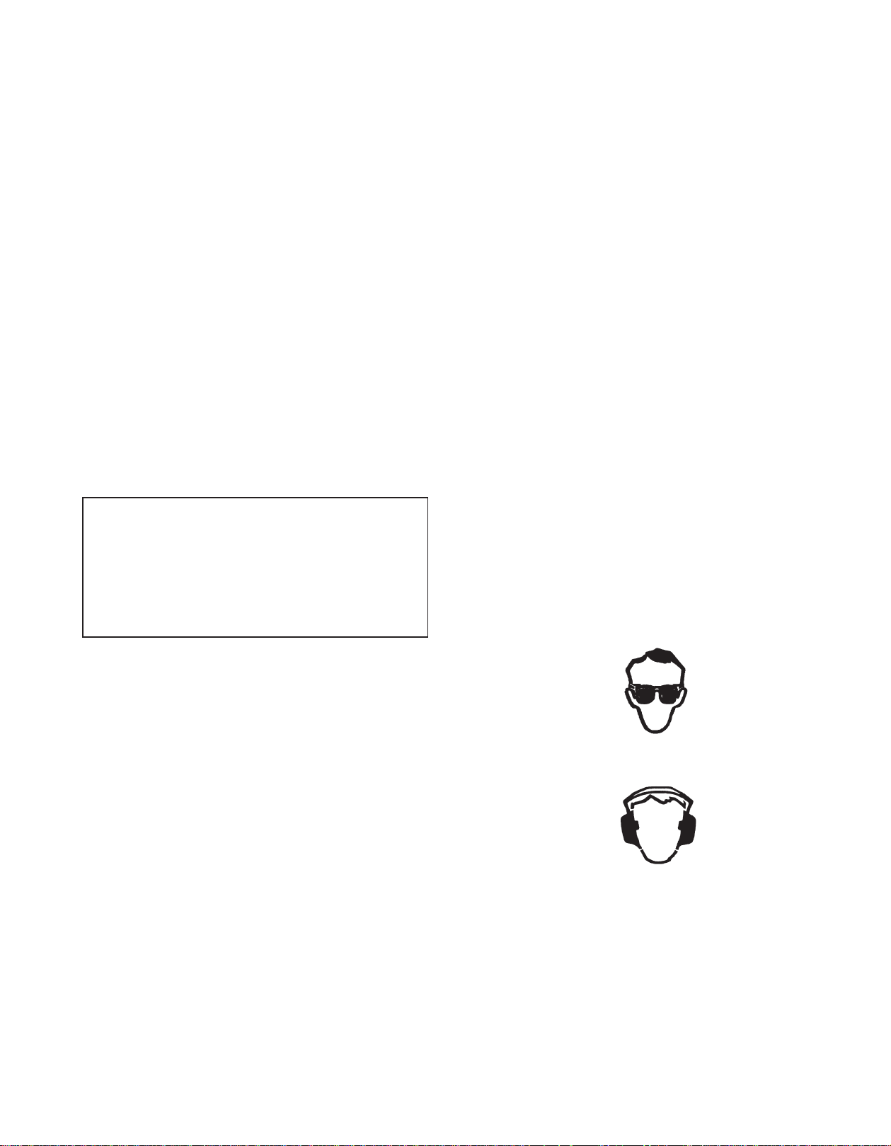
2. Never allow children to operate the Pruner. It is
not a toy. Never allow adults to operate the unit
without first reading the Owner’s/Operator’s
Manual.
3.
Always wear eye protection that complies with ANSI
(American National Standards Institute) Z87-1.
4. Always wear hearing protection.
5. Always wear heavy, long pants, a long sleeved
shirt, boots and gloves. Do not wear loose clothing, jewelry, short pants, sandals, or go barefoot.
Secure hair so it is above shoulder length.
6. Never operate this Pruner when you are tired, ill,
or under the influence of alcohol, drugs or
medication.
— —
Page 6
Page 7
Safety and Instruction Decals
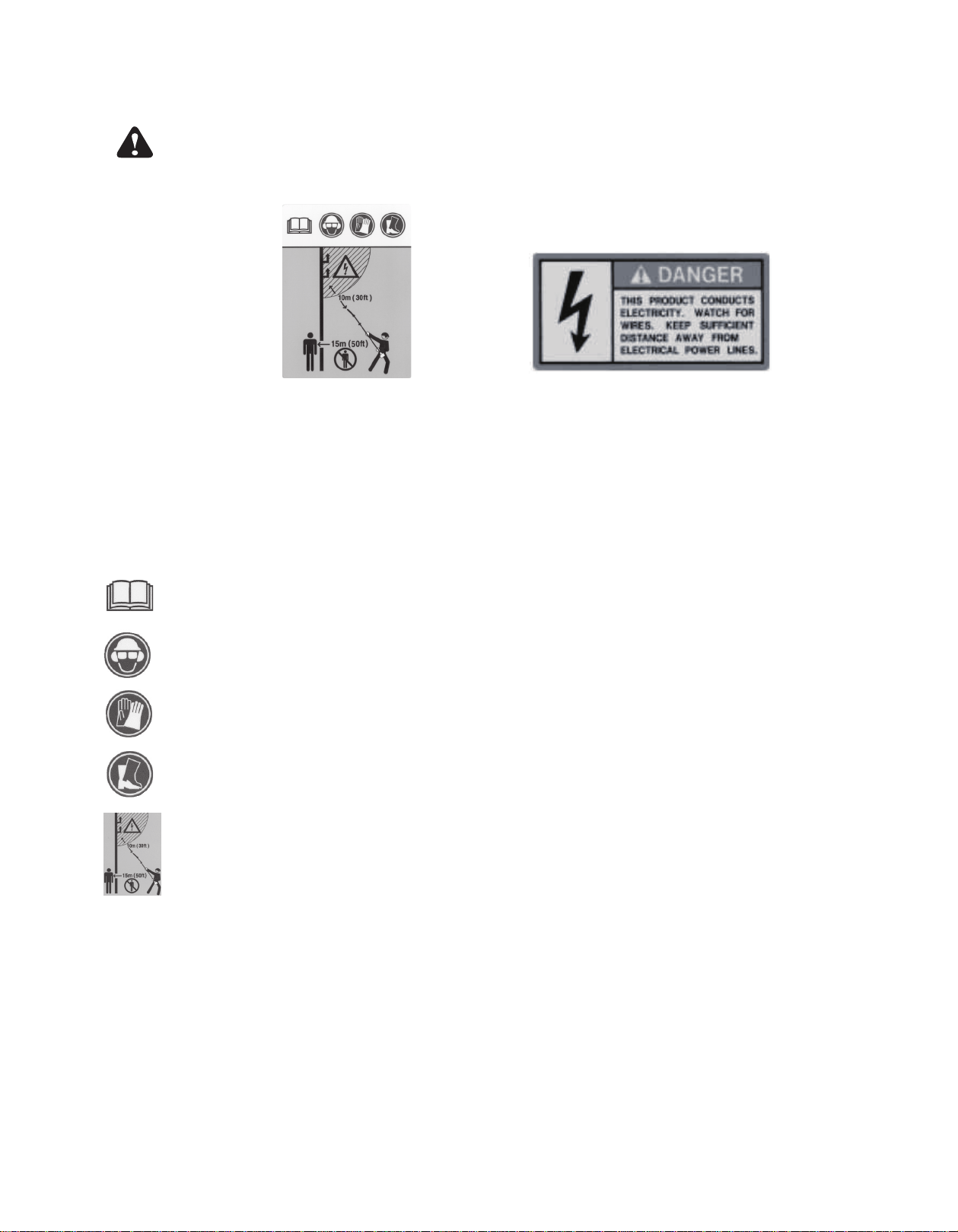
Safety Decals and instructions are easily visible to the operator and are located near any area of
potential danger. Replace any decal that is damaged or lost.
(Part No. 231896)
Symbol explanation
Read and understand this Owner’s/ Operator’s Manual.
•
Wear head protection, where there is a risk of falling objects.
•
Wear eye protection, while operating the Pruner.
•
Wear ear protection, while operating the Pruner.
Wear gloves, while operatingthe Pruner.
Wear foot protection, while operating the Pruner.
ON SHAFT
ON SHAFT
(Part No. 219937)
•
The distance between the machine and bystandards shall be at least 15m.
•
Watch for electrical shock. Keep sufficient distance away from electrical power line.
•
The distance between the machine and electrical power line shall be at least 10m (30ft.).
— —
Page 8
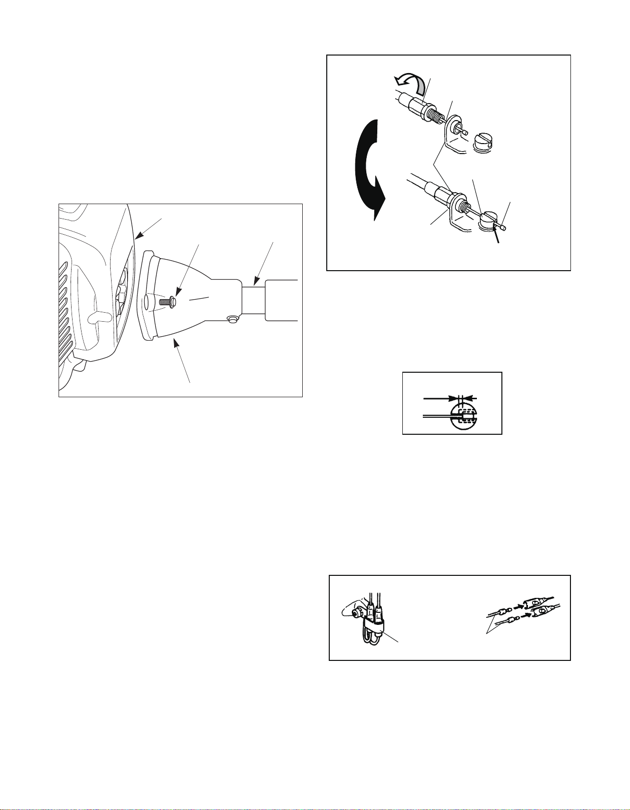
Assembly
Cable Adjuster Sleeve
Assembling Engine and Drive Shaft
Assembly
The drive shaft and clutch drum housing are assembled. Attach the clutch drum housing to the engine
using the four M5 x 20 screws supplied with the unit.
Engine
M5 x 20 Screw (4)
Clutch Drum Housing
Shaft
Throttle Cable
Carburetor
Bracket
Lock nut
Slotted Fitting
Cable Lug
Recessed Hole
5. Adjust the cable adjuster sleeve so the stop on the
carburetor throttle cam just contacts the throttle
stop and the cable position keep 1-2mm play
between cable lug and slotted fittings when the
throttle trigger is fully depressed.
1-2mm Play
Connecting Throttle Cable and Stop
Switch Wires
1. Loosen the knob and remove the air filter cover,
insert the throttle cable through the carburetor
bracket, then screw a cable adjuster sleeve into the
carburetor bracket fully.
2. Position the slotted fitting on the carburetor so the
recessed hole for the lug is away from the cable
adjuster sleeve.
Rotate the carburetor throttle cam and slip the throt-
3.
tle cable through the slot in the slotted fitting, making sure the cable lug drops into the recessed hole.
4. Operate the throttle trigger a few times to make
sure that it works correctly.
6. When the throttle cable is adjusted correctly,
tighten the lock-nut.
7. Plug the stop switch wires into the matching connectors from the engine. Note that wire polarity is
not important.
8. Lap and fix the stop switch wires and connectors
with clamp.
Clamp
Stop Switch Wires
9. Reinstall the air filter cover and tighten the knob.
— —
Page 9
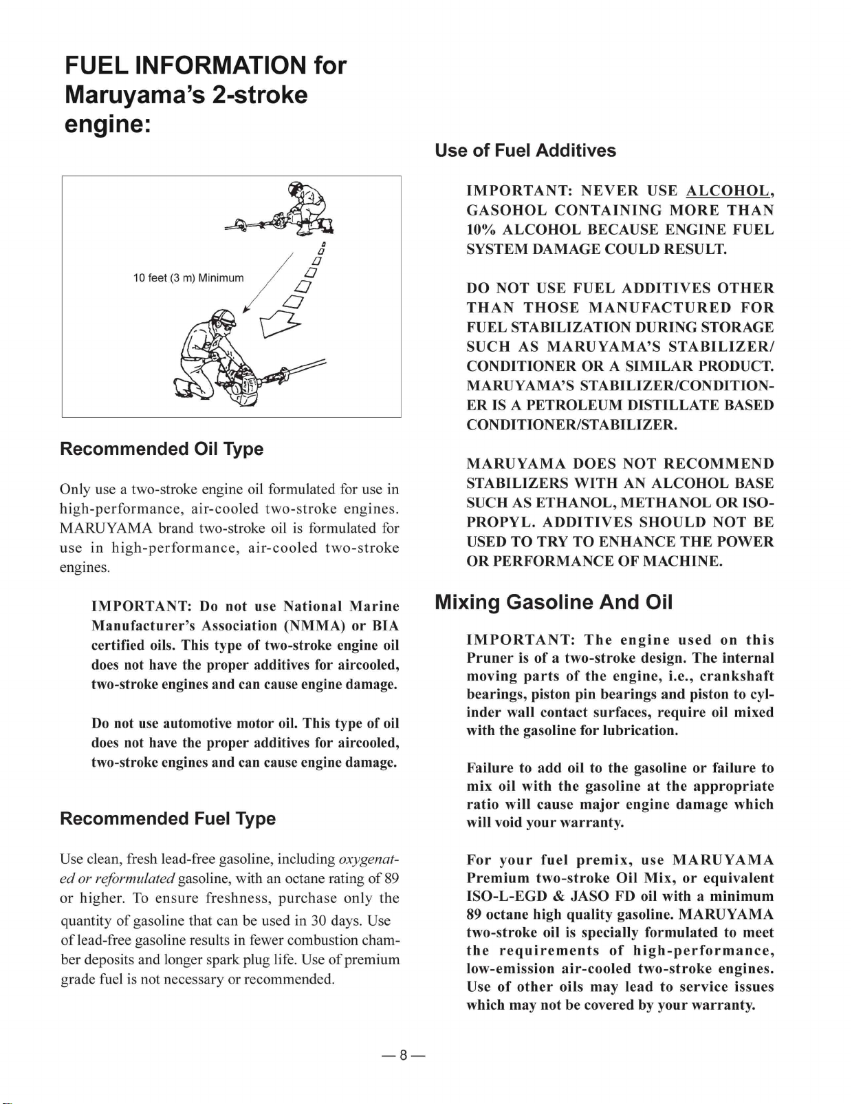
Page 10
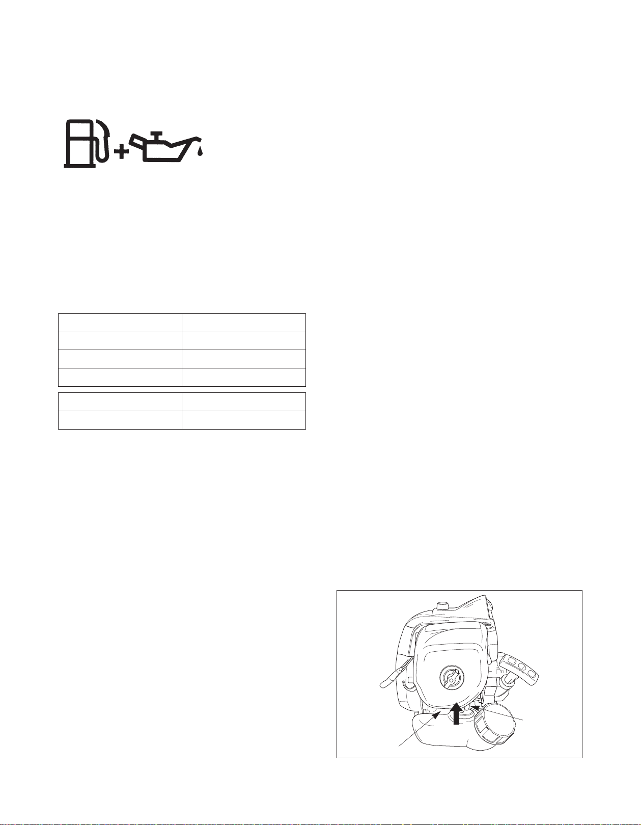
Fuel Mixture
The fuel: oil ratio is 50 parts gasoline to 1 part oil or
50:1.
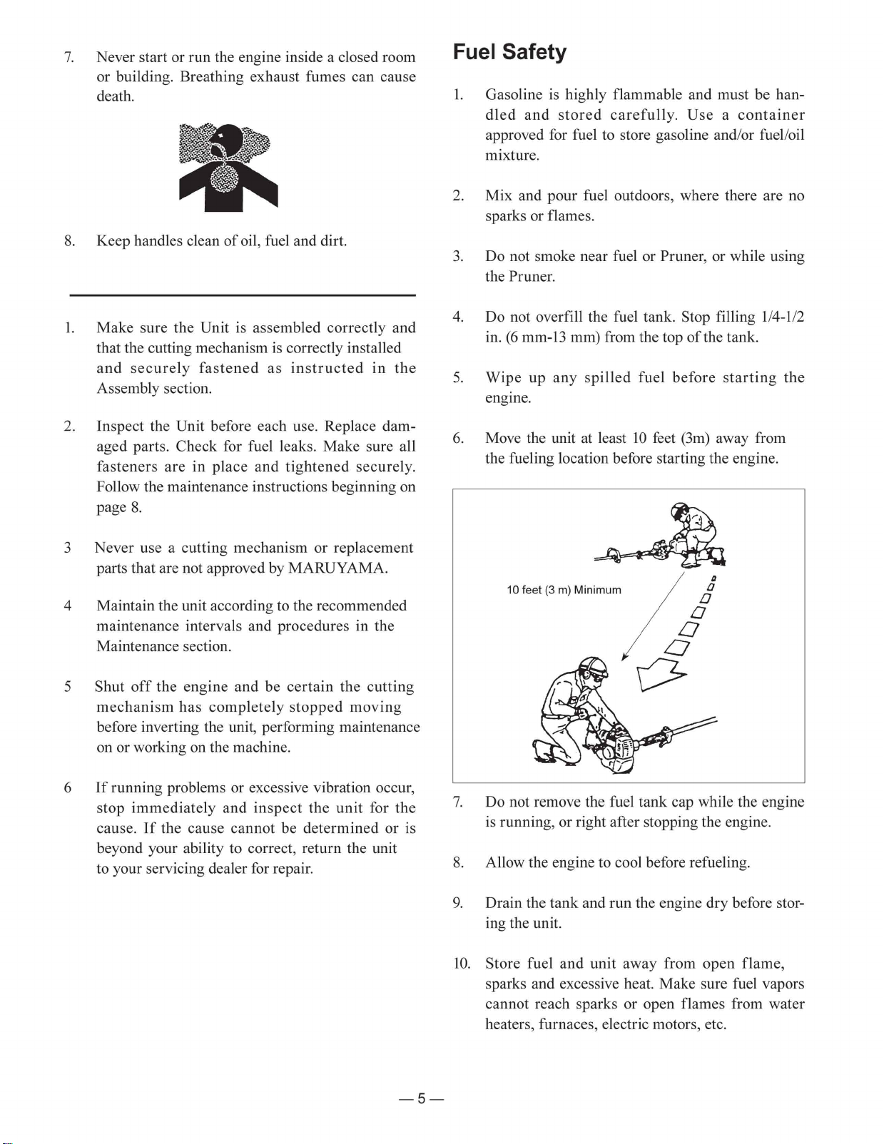
6. When refilling the Pruner fuel tank, clean around
the fuel tank cap to prevent dirt and debris from
entering the tank during cap removal.
7. Always shake the premix fuel container momentarily before filling the fuel tank.
50:1
Note: Never use a mixing ratio less than
50:1 regardless of the oil package
mixing instructions. Ratios less than
50:1, (for example, 60:1, 80:1, 100:1),
reduce the amount of lubrication to
the internal moving parts of the
engine and can cause damage.
Fuel Mixture Chart
Gasoline 50:1 two-stroke oil
1 gallon 2.6 oz
2 gallons 5.1 oz.
5 gallons 12.8 oz.
1 liter 20 mL
5 liters 100 mL
.
8. Always use a spout or funnel when fueling to
reduce fuel spillage.
9. Fill the tank only to within 1/4-1/2 in. (6 mm-13
mm) from the top of the tank. Avoid filling to the
top of the tank filler neck.
Starting And Stopping
Before Starting The Engine
1. Fill the fuel tank as instructed in the Before
Operation section of this manual (US-14).
2. Rest the Pruner on the ground.
3. Make sure the chain and guide bar are clear of any
broken glass, nails, wire, rocks or other debris.
4. Keep all bystanders, children and animals away
from the working area.
Cold Starting Procedure
Mixing Instructions
IMPORTANT: N(9(5 mix gasoline and oil
directly in the XQLWV fuel tank.
1. Always mix fuel and oil in a clean container
approved for gasoline.
2. Mark the container to ,'(17,)< it as fuel 0,;
IRUthe VWURNHXQLW.
3. Use regular unleaded gasoline and fill the container with +$/) the required amount of gasoline.
4. Pour the correct amount of 2,/ into the container
$1'7+(1$''the remaining amount of gasoline.
5. Close the container tightly and shake it momentarily to evenly mix the oil and the gasoline before
filling the fuel tank.
This XQLW is equipped with a fuel primer and a choke
system. To start a “cold” engine properly, perform the
following procedure:
1. Pump the primer bulb at the bottom of the carburetor until fuel can be seen flowing through the
fuel return line to the fuel tank.
(Flowing fuel should be almost clear, not foamy
or full of bubbles.)
Fuel
Return
Line
Primer Bulb
— —
Page 11
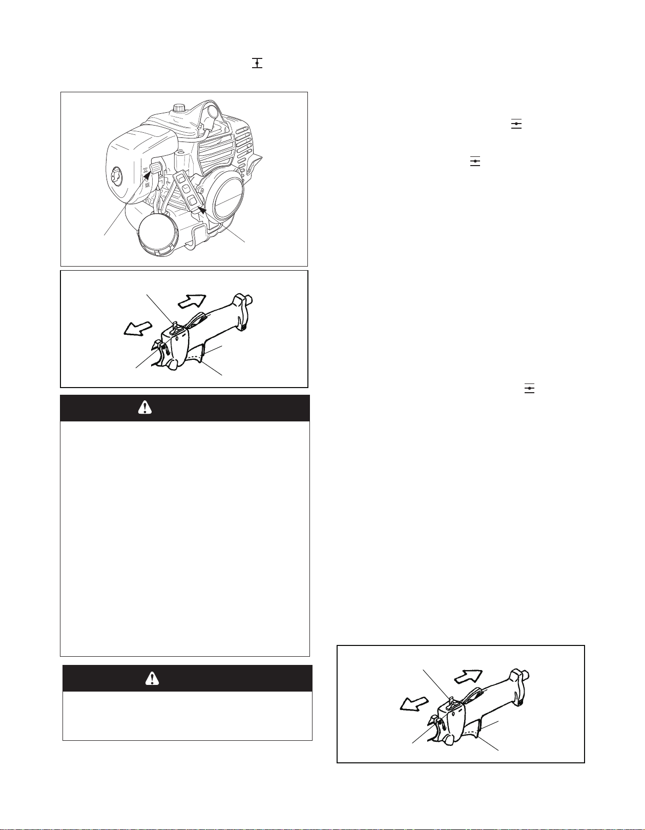
2. Move the choke lever to the closed ( ) position
4. If the engine fails to start after three to four pulls,
follow the instruction in the Cold Starting Procedure
section (page US-17).
If the engine fails to start after you follow the
above procedures, contact an authorized
Maruyama dealer.
To Stop The Engine
1. Release the throttle trigger.
2. Slide the stop switch to the “STOP” position.
)
(ON)
t
t
4. If the engine fails to start after three to four pulls,
follow the instruction in the Cold Starting Procedure
section (page US-17).
If the engine fails to start after you follow the
above procedures, contact an authorized
Maruyama dealer.
To Stop The Engine
1. Release the throttle trigger.
2. Slide the stop switch to the “STOP” position.
)
(ON)
t
t
and move the stop switch to the “ON” position.
Choke Lever
Fas
-idle start lock
STOP(OFF
Stop switch
START
Starter Grip
Fas
-idle start
position
Idle position
WARNING
3. Lock the throttle trigger in the fast-idle start position, then pull the starter grip.
4. After the engine starts, squeeze and release the
throttle trigger to return it to the idle position, then
move the choke lever to the open (
) position.
If the engine stops running before you move the
choke lever to the open (
) position:
A. Go ahead and open the choke.
B. Make sure the throttle trigger is set to the fast-
idle position.
C. Pull the starter grip until the engine starts.
Hot Restart
To start an engine that is already warmed up (hot
restart), or if the ambient temperature exceeds 68°F
(20°C):
1. Pump the primer bulb at the bottom of the carburetor until fuel can be seen flowing through the
fuel return line to the fuel tank.
2. Move the choke lever to the open (
and move the stop switch to the “ON” position.
) position
POTENTIAL HAZARD
• The components of your recoilstarter
assembly are under high spring tension.
If improperly disassembled these parts
maystrike you with considerable force,
possibly causing personal injuly.
WHAT CAN HAPPEN
• Contact with the parts can cause severe
personal injury.
HOW TO AVOID THE HAZARD
• Never attempt to disassemble your
recoil starter assembly yourself.
Always consult your authorized
MARUYAMA dealer for repair by quali
fied service technicians.
CAUTION
• Do not pull the Starter rope all the way
out.
3. Leave the throttle trigger in the idle position and
pull the starter grip.
4. If the engine fails to start after three to four pulls,
follow the instruction in the Cold Starting
Procedure section (US-17).
If the engine fails to start after you follow the
above procedures, contact an authorized
MARUYAMA dealer.
To Stop The Engine
1. Release the throttle trigger.
-
2. Slide the stop switch to the “STOP” position.
Fas
-idle start lock
STOP(OFF
Stop switch
START
Fas
-idle start
position
Idle position
— —
Page 12
Maintenance
Maintenance, replacement or repair of emission
control devices and systems may be performed by
any repair establishment or individual; however,
warranty repairs must be performed by a dealer or
service center authorized by MARUYAMA
Manufacturing Company, Inc. The use of parts that
are not equivalent in performance and durability to
authorized parts may impair the effectiveness of the
emission control system and may have a bearing on
the outcome of a warranty claim.
Maintenance on today’s low-emission engines is
even more critical for longest life and best performance. particularly critical are air and fuel filters,
spark plug heat range, cooling air intake area and
proper gaps of coil and plug.
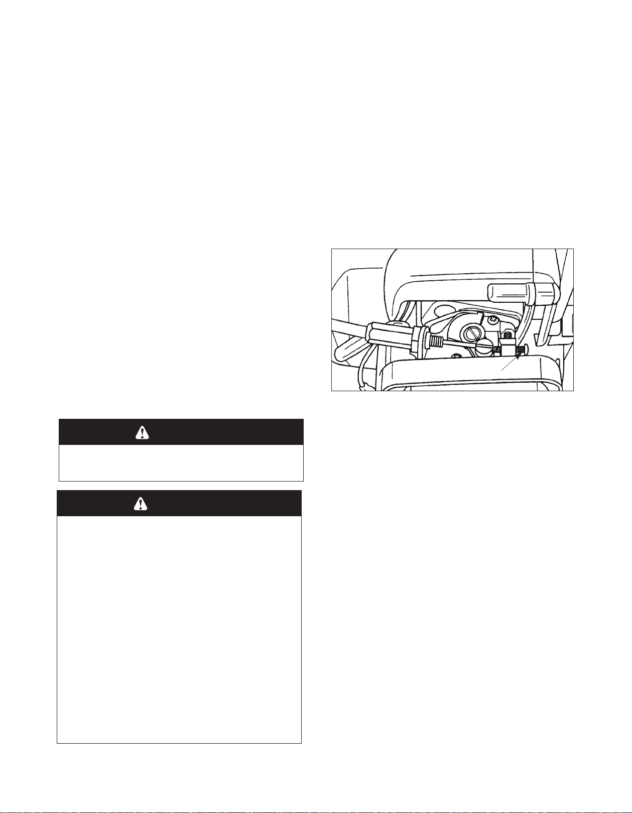
Idle Speed Adjustment
The cutting head may be rotating during idle speed
adjustment. Wear the recommended personal protective equipment and observe all safety instructions.
Keep hands and body away from the cutting head.
When the throttle trigger is released, the engine should
return to an idle speed between 2700 and 3300 RPM,
or just below the clutch engagement speed. The cutting
head must not rotate and the engine should not stall
(stop running) at engine idle speed.
To adjust the engine idle speed, rotate the idle speed
adjustment screw on the carburetor.
This HQJLQH is equipped with Dnon-adjustable fuel
PL[ture carburetor. The engine idle speed is the
RQO\adjustment for the operator.
WARNING
• Idle speed adjustment should be
checked each time the unit is operated.
WARNING
POTENTIAL HAZARD
• Engine must be running to make carburetor adjustments.
When engine is running, saw chain is
•
moving and other parts are moving.
WHAT CAN HAPPEN
• Contact with moving saw chain or other
moving parts could cause serious per
sonal injur y or death.
HOW TO A
• Keep hands, feet and clothing away from
saw chain and other moving parts.
• Keep all bystanders and pets away from
unit while making carburetor adjust-
ments.
VOID THE HAZARD
-
Idle Speed
Adjustment Screw
• Turn the idle speed screw in (clockwise) to
increase the engine idle speed.
• Turn the screw out (counterclockwise) to decrease
the engine idle speed.
If idle speed adjustment is necessary, and after
adjustment the cutting head rotates or the engine
stalls, stop using the Pruner immediately!
Contact your local authorized MARUYAMA Dealer
for assistance and servicing.
Air Filter
Maintenance Interval
• The air filter should be cleaned daily, or more
often when working in extremely dusty
conditions.
• Replace after every 100 hours of operation.
— —
Page 13
Air Filter Cleaning
2. Remove the fuel cap.
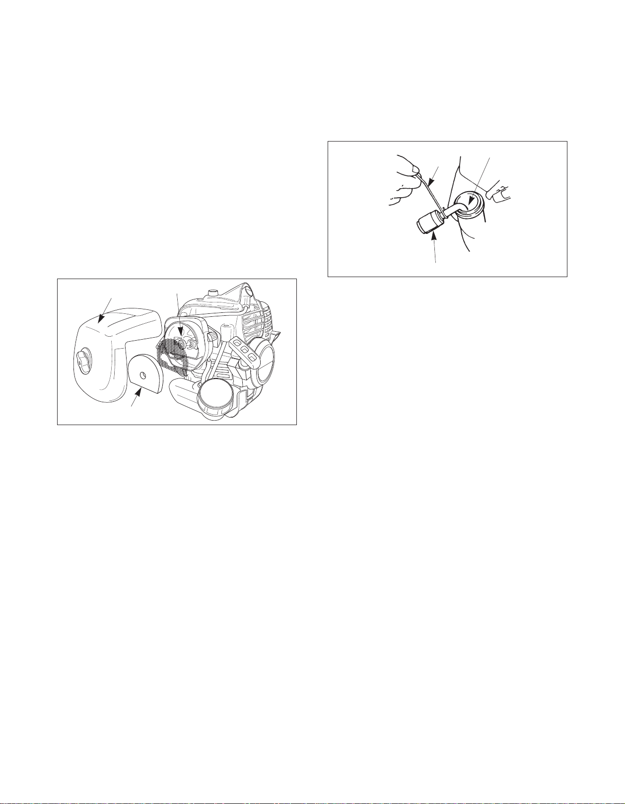
1. Loosen the knob and remove the air filter cover.
2. Remove the foam element and filter screen from
the air filter body.
3. Clean the foam element and filter screen with
warm, soapy water. Let the screen and element
dr y completely.
4. Apply a light coat of SAE 30 motor oil to the
foam element and squeeze out all excess oil.
5. Reassemble the filter screen and foam element to
the air filter body.
Air Filter Cover
Filter Screen
3. Using a wire hook, gently pull the fuel filter out
through the fuel filler opening.
Use caution not to “fishook” the fuel tube.
Replace immediately if punctured!
Fuel Pick-up Hose
Wire
Fuel Filter
4. Grasp the fuel hose next to the fuel filter fitting
and remove the filter, but do not release the hose.
5. While still holding on to the fuel hose, attach the
new fuel filter.
Foam Element
6. Reinstall the air filter cover and tighten the knob.
Fuel Filter
Maintenance Interval
The fuel filter should be replaced after every 100 hours
of operation.
Fuel filters needing more frequent replacement may
indicate debris in fuel tank.
Fuel Filter Replacement
The fuel filter is attached to the end of the fuel pick-up
hose inside the fuel tank.
To replace the fuel filter:
6. Drop the new fuel filter back into the fuel tank.
7. Make sure that the fuel filter is not stuck in a corner of the tank, and that the fuel hose is not doubled over (kinked) before refueling.
Spark Plug
Maintenance Interval
• The spark plug should be removed from the
engine and checked after each 25 hours of
operation.
• Replace the spark plug after every 100 hours of
operation.
Spark Plug Maintenance
1. Twist the high tension lead boot on the spark plug
back and forth a couple of times to loosen the
boot, then pull the boot off of the spark plug.
1. Make sure the fuel tank is empty.
2. Remove the spark plug.
— 2 —
Page 14
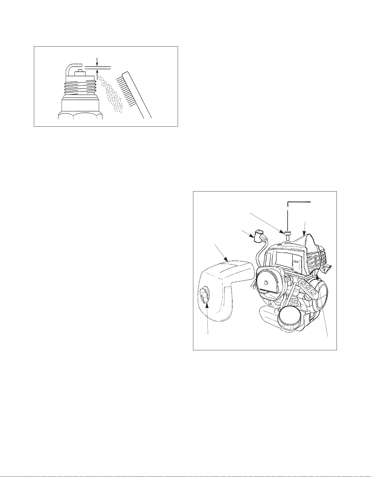
3. Clean the electrodes with a stiff brush.
Cylinder Cooling Fins
.024” - .028” (0.6 - 0.7 mm)
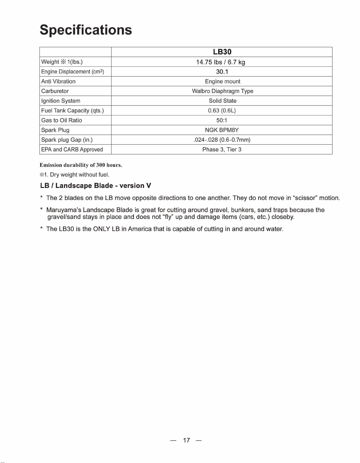
4. Adjust the electrode air gap to .024-.028 in. (0.6-
0.7 mm).
5. Replace the spark plug if it is oil-fouled, damaged,
or if the electrodes are worn down.
6. Do not overtighten the spark plug when installing.
The tightening torque is 95-148 in.-lbs. (10.7-16.6
N·m).
7. Always use only the specific heat range of spark
plug. This is particularly critical with today's lowemission engines. For best results, use the exact
replacement.
Maintenance Interval
• The cylinder cooling fins should be cleaned after
every 25 hours of operation, or once a week,
whichever comes first.
• Air must flow freely around and through the cylinder cooling fins to prevent engine overheating.
Leaves, grass, dirt and debris buildup on the fins
will increase the operating temperature of the
engine, which can reduce engine performance and
shorten engine life.
Cooling Fin Cleaning
1. With the engine at ambient (room) temperature,
loosen the knob and remove the air filter cover.
Knob
Cylinder Cover
High Tension Lead Boot
Air Filter Cover
— 3 —
Knob
Cooling Fins
2. Twist the high tension lead boot on the spark plug
back and forth a couple of times to loosen the
boot, then pull the boot off of the spark plug.
3. Loosen the knob and lift off the cylinder cover.
4. Clean all dirt and debris from the cooling fins and
from around the cylinder base.
Page 15
Page 16
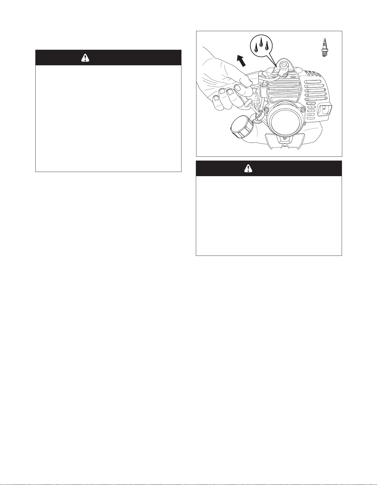
General Cleaning and Tightening
WARNING
POTENTIAL HAZARD
• When engine is running, saw chain is
moving and other parts are moving.
WHAT CAN HAPPEN
• Contact with moving saw chain or other
moving parts could cause serious per
sonal injury or death.
-
HOW TO AV
•
Always turn off your pruner before
you clean or perform any maintenance
on it.
The MARUYAMA XQLW will provide maximum performance for many, many hours if it is maintained
properly.
Good maintenance includes regular checking of all fasteners for correct tightness and cleaning the entire
machine.
OID THE HAZARD
Storage
For long term storage of the Pruner:
1. Empty the fuel tank into a suitable fuel storage
container.
2. Pump the primer bulb on the carburetor until all
fuel is discharged through the clear fuel return
hose.
CAUTION
POTENTIAL HAZARD
• Oil may squirt out of the spark plug
opening when you pull the starter grip.
WHAT CAN HAPPEN
• Oil can cause eye injuries.
HOW TO AVOID THE HAZARD
• Protect your eyes and keep your face
away from the spark plug opening.
6. Pull the starter grip once.
7. Slowly pull the starter grip to bring the piston to
the top of the cylinder (TDC).
8. Reinstall the spark plug.
9. Store the XQLW in a dry place away from excessive heat, sparks or open flame.
3. Run the engine to remove any fuel that may
remain in the carburetor.
4. Perform all regular maintenance procedures and
any needed repairs.
5. Remove the spark plug and squirt a very small
amount of oil into the cylinder.
— —
Page 17

Troubleshooting
Problem Cause Action
Engine Will Not Start STOP switch set to off position
Empty fuel tank
Primer bulb wasn’t pushed enough
Engine ooded
Engine Will Not Idle Idle speed set incorrectly Set idle speed
Engine Lacks Power or Stall When
Cutting
If further assistance is required, contact your local authorized MARUYAMA service dealer.
Throttle wire has come loose
Dirty air lter
Clogged spark arrester or exhaust port.
Move switch to on position
Fill fuel tank
Press primer bulb until fuel flows
through fuel return line
Use warm engine starting procedure
Tighten throttle wire
Clean or replace air filter
Clean spark arrester or exhaust port.
Maintenance Period
Maintenance Daily
Check and replenish fuel
Check for fuel leakage
Check bolts, nuts and screws for tightness or missing
●
●
●
Every
25 hours
Every
50 hours
Every
100 hours
Check engine idle speed adjustment
Clean air lter element
■
Clean spark plug and adjust eleatrode gap
Remove dust and dirt from cylider ns
■
Clean spark arrester
●
Tighten bolts and nuts
Remove carbon deposits in exhaust port
●
Replace fuel lter
Remove carbon deposits on piston head and combustion chamber
●
Remove carbon deposits in transfer port
●
Replece fuel tube, fuel tank cap gasket It is recommended to replace every 3 years
●: Service to be performed by an authorized MARUYAMA engine dealer.
■: Service more frequently under dusty conditions.
NOTE:
The service intervals indicated are to be used as a guide.
Service to be performed more frequently as necessary depending on operating condition.
Use MARUYAMA standard 50:1 two-stroke engine oil.
●
●
●
●
●
●
●
●
●
●
— —
Page 18
Page 19
LANDSCAPE BLADE
ATTACHMENT
P r e m i u m O u t d o o r P o w e r E q u i p m e n t E x t r a o r d i n a r y .
O P E R A T O R ' S M A N U A L
Co m p l e t ely read a n d u nderstan d t h i s manual p r i o r to using t h i s product .
Type 5
Page 20
Page 21
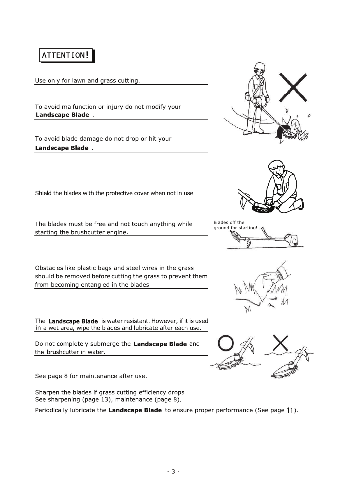
Page 22
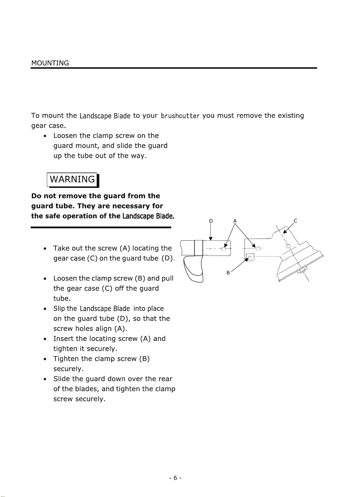
Page 23
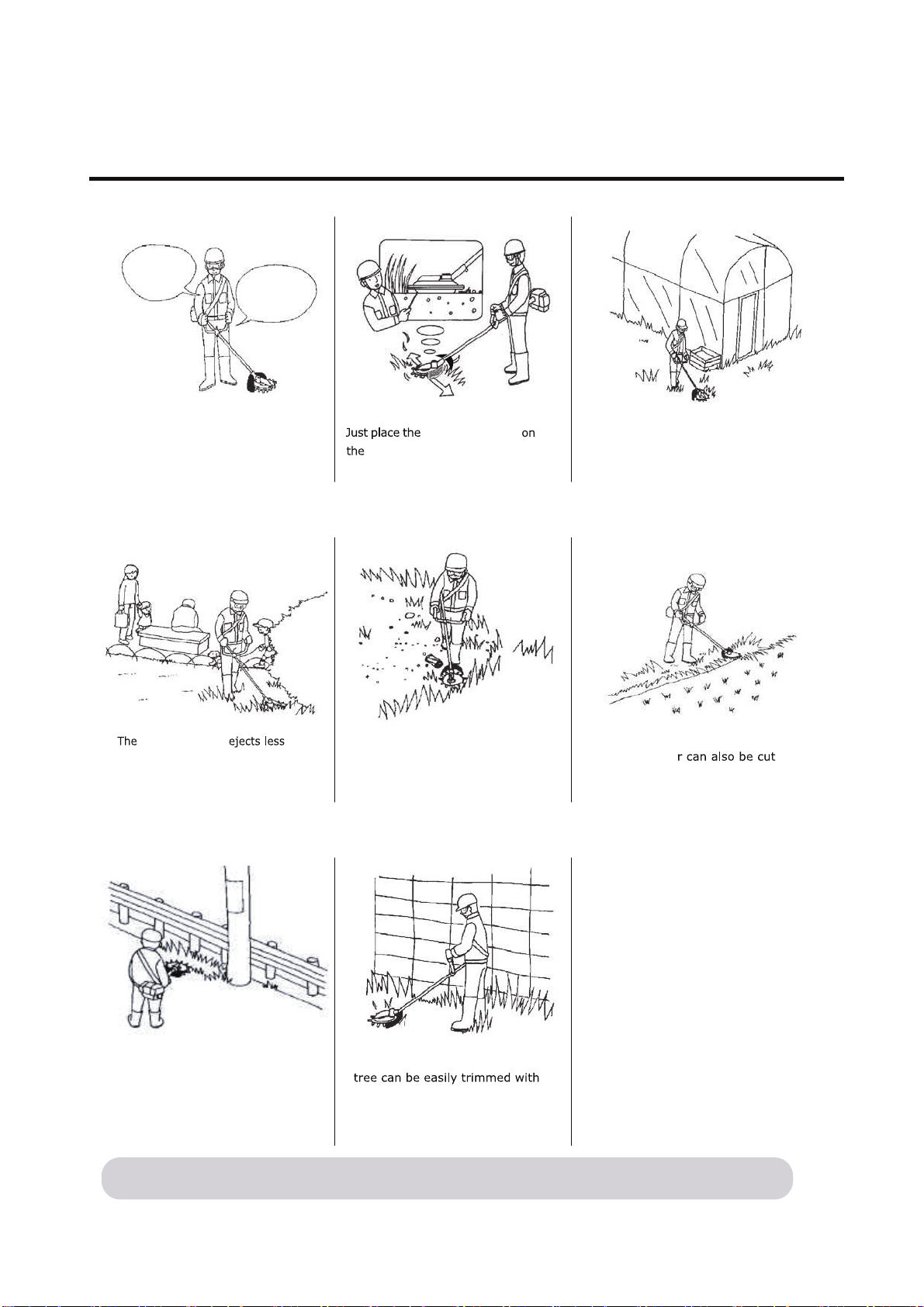
- 7 -
OPERATION
Grass cutting work can be done in a
place with lots of stones, or cans.
dangerous flying debris than a
conventional string trimmer.
There is a minimal risk of
damage to glass windows by
flying debris.
Grass close to a wall, solid fence or
Grass on the edge of the road, or
around poles can be cut with
ease.
Grass in a wet area or even in
shallow wate
with ease.
minimal damage because of blunt
edged blades and minimal back
because the blades counter rotate.
ground and swing it for easy and
comfortable grass cutting work.
Adjust the shoulder strap and
grip position, so that the blade
face is parallel to the ground.
Strap
O K
Grip
Landscape Blade
Landscape Blade
7KLVSURGXFWFDQVXSSUHVVIO\LQJVWRQHV
$OWKRXJKLWLVQRWQHFHVVDU\WKDWZLWKRXWIO\LQJ
0DNHVXUHWKHVDIHW\FRQILUPDWLRQWRWKHVXUURXQGLQJV
DQGZHDUVDIHW\JODVVHVZKLOHXVLQJ
Page 24
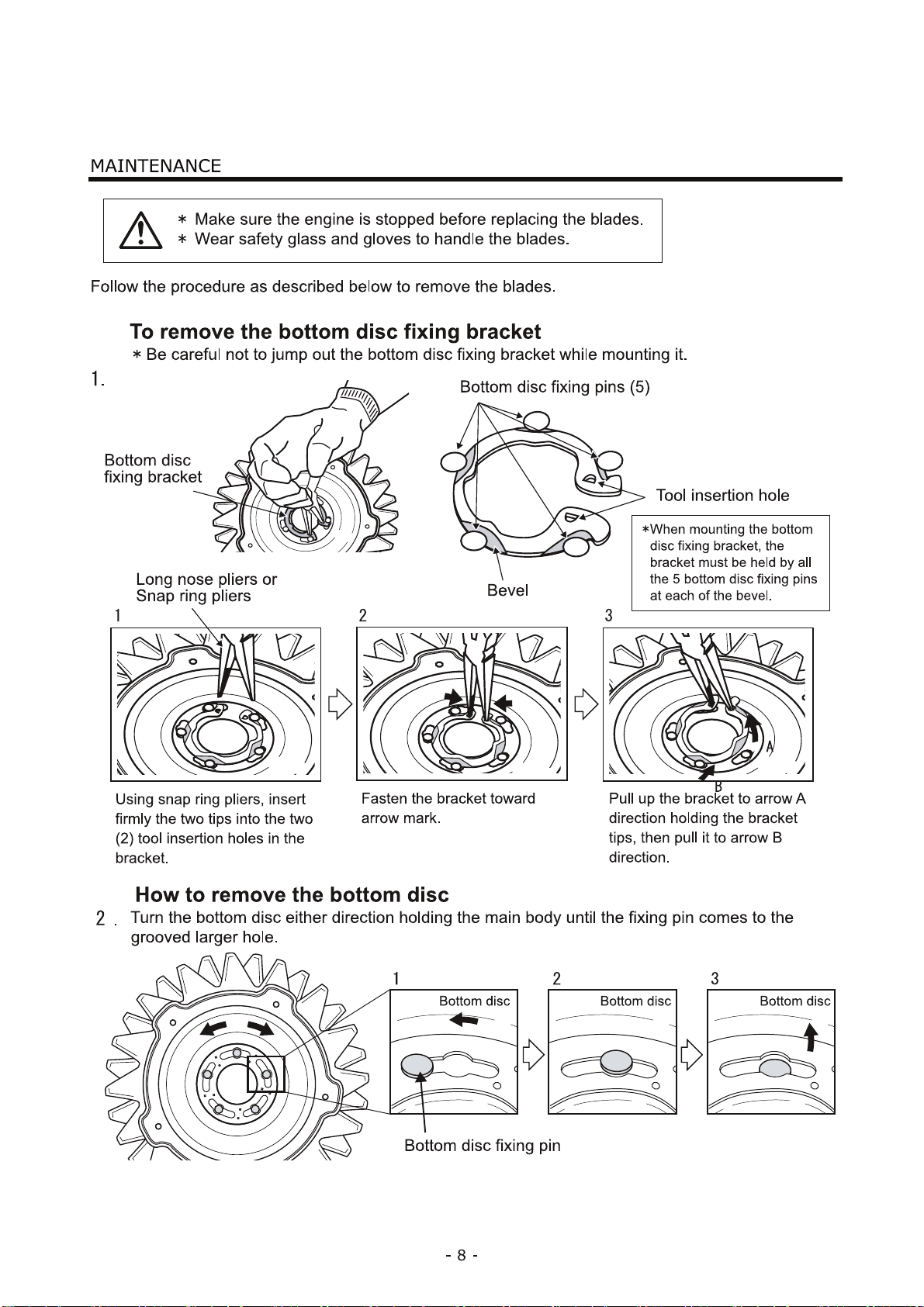
Page 25
Page 26
Page 27
- 11 -
Injection hole
Grease injection hole
Lubrication
1
2
3
4
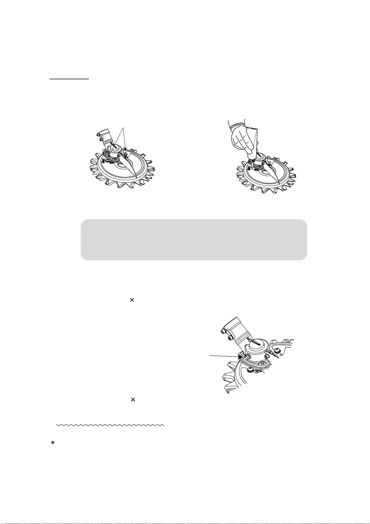
Remove the two screws to allow grease to be injected (see illustration), and inject grease
into both screw holes. Inject about 20cc per every 10 hours of operation as a reference.
Insert the two screws and tighten securely.
Remove hex screw (M5 6) in the gear case, and inject about 10cc of grease into the hole
every 25 hours of operation as a reference.
Insert the hex screw(M5 6) and tighten it securely.
This completes lubrication
/XEULFDWHWKH3RZHU5RWDU\6FLVVRUVDQGRLOWKHEODGHVLILWLVWREHVWRUHGIRUPRUHWKDQGD\V
'RQRWUHSODFHWKHVFUHZVZLWKWKHJOHDVHQLSSOH
,WPD\EHORRVHQHGE\YLEUDWLRQGXULQJXVH
0DNHVXUHWRXVHWKHJHQXLQHWKHZDVKHUEXLOWLQVFUHZ
Page 28
Page 29
$6.9%06
㸦,QFOXGLQJJHDUFDVH㸧
Page 30
Page 31
Page 32

 Loading...