

Page 1
TACOMA HV SERIES
1K ~ 3KVA
On-Line UPS
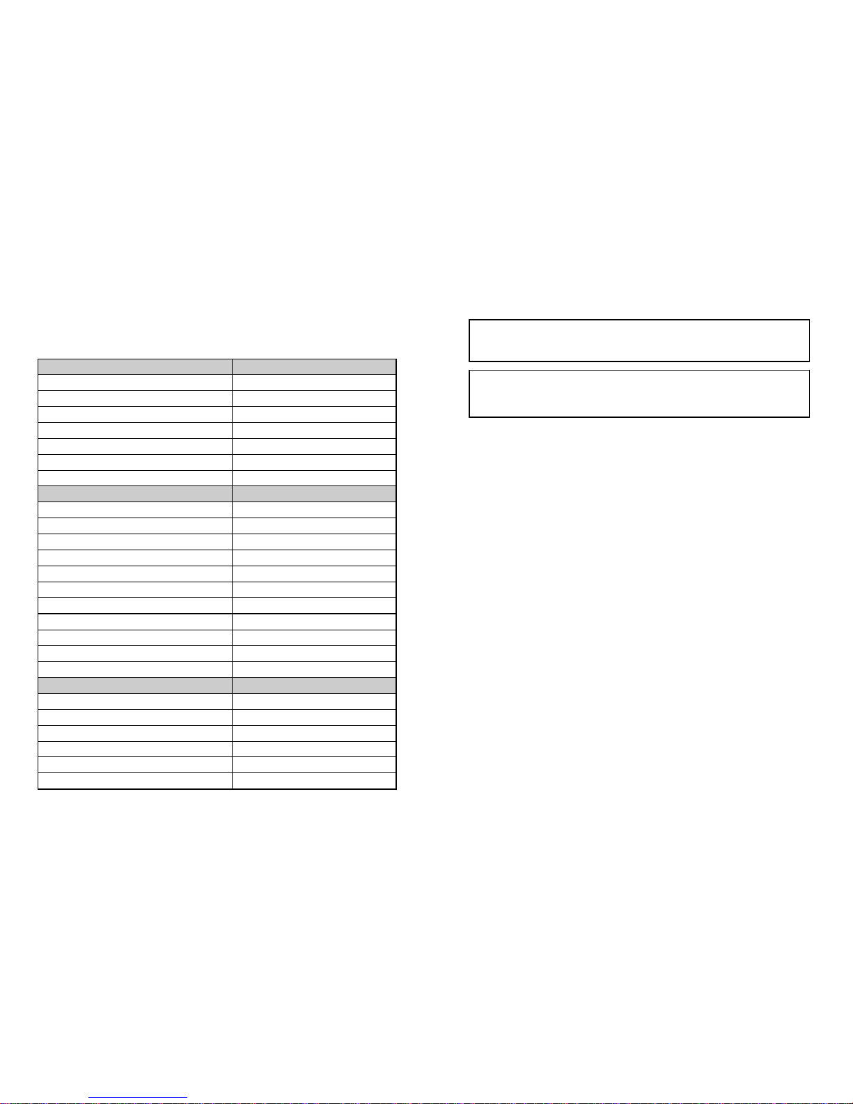
USER MANUAL
Maruson Technology Corporation
P.O. Box 1986, Walnut, CA 91788 USA
Toll Free: 1-888-MARUSON
Website: www.MarusonUSA.com | E-Mail: [email protected]
*Copyright © 2012 All Rights Reserved. Maruson® is a registered trademark of Maruson Technology
(U.S. Trademark Reg. No. 3,150,957). All other trademarks are the property of their respective owners.
Product specifications are subject to change without notice. Battery backup time is based on half load
and varies with equipment, configuration, battery age, temperature, etc.
Page 2

CONTENT
1. Safety and EMC Instructions.....................................................1
1.1 Installation.........................................................................................1
1.2 Operation..........................................................................................2
1.3 Maintenance, servicing and faults....................................................3
1.4 Transport...........................................................................................4
1.5 Storage .............................................................................................4
1.6 Standards..........................................................................................5
2. Description of Commonly Used Symbols...................................6
3. Introduction .............................................................................7
4. Panel Description.....................................................................8
5. Connection and Operation...................................................... 12
5.1 Inspection: ......................................................................................12
5.2 Connection:.....................................................................................12
5.3 Battery charge:...............................................................................14
5.4 Turn on the UPS:............................................................................14
5.5 Test function:...................................................................................15
5.6 Turn off the UPS:............................................................................15
5.7 Audible alarm mute function:..........................................................16
5.8 Operation procedure of external battery for long backup time model
(“L” model) ............................................................................................16
6. Operating Mode for All Models ................................................18
6.1 Line mode.......................................................................................18
6.2 Battery mode ..................................................................................19
6.3 Bypass mode..................................................................................21
6.4 NO output mode.............................................................................21
6.5 EPO (Emergency Power Off).........................................................22
Page 3

6.6 ECO mode (Economy mode).........................................................22
6.7 Converter mode..............................................................................23
6.8 Abnormal mode..............................................................................23
7. Setting by LCD Module...........................................................24
8. Trouble Shooting....................................................................27
9. Maintenance ..........................................................................31
9.1 Operation........................................................................................31
9.2 Storage ...........................................................................................31
9.3 Battery Replace..............................................................................31
10. Technical Data......................................................................32
10.1 Electrical specifications................................................................32
10.2 Operating Environment ................................................................32
10.3 Typical backup time (Typical values at 25°C in minutes:)................33
10.4 Dimensions and weights ..............................................................33
11. Communication Port .............................................................34
11.1 USB...............................................................................................34
11.2 AS400 Interface (Option)..............................................................34
12. Software...............................................................................35
Appendix: Rear panel.................................................................36
Page 4
-38-
614-06810-02
-1-
1. Safety and EMC Instructions
Please read carefully the following user manual and the
safety instructions before installing the unit or using the unit!
1.1 Installation
See installation instructions before connecting to the supply.
Condensation may occur if the UPS is moved directly from a cold
to a warm environment. The UPS must be absolutely dry before
being installed. Please allow an acclimatization time of at least
two hours.
Do not install the UPS near water or in damp environment.
Do not install the UPS where it would be exposed to direct
sunlight or near heat.
Do not connect appliances or items of equipment which would
overload the UPS (e.g. laser printers, etc) to the UPS output.
Place cables in such a way that no one can step on or trip over
them.
Assure to connect with the earth reliably.
Assure external battery source must be earthed.
Connect the UPS only to an earthed shockproof socket outlet.
The building wiring socket outlet (shockproof socket outlet) must
be easily accessible to close to the UPS.
With the installation of the equipment, the sum of the leakage
current of the UPS and the connected load does not exceed
3.5mA.
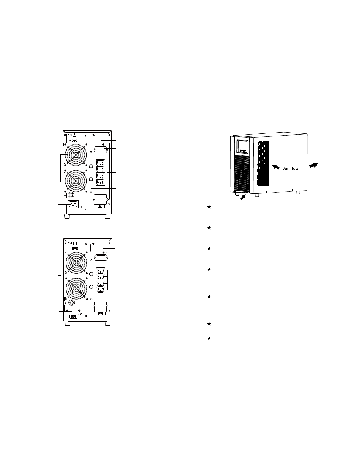
Do not block ventilation openings in the UPS’s housing. Ensure
the air vents on the front, side and rear of the UPS are not
blocked. Allow at least 25cm of space on each side.
Page 5
-2-
UPS has provided earthed terminal, in the final installed system
configuration, equipotential earth bonding to the external UPS
battery cabinets.
An appropriate disconnect device as short-circuit backup
protection should be provided in the building wiring installation.
Please see the disconnect device specification in chapter 5.2.
Equipment the powered more than one source.
1.2 Operation
Do not disconnect the mains cable on the UPS or the building
wiring socket (grounded shockproof socket) during operation as
this would remove the ground to the UPS and of all connected
loads.
The UPS features its own, internal current source (batteries). You
may be electric shock when you touch the UPS output sockets or
output terminal block even if the UPS is not connected to the
building wiring socket.
In order to fully disconnect the UPS, first press the OFF button to
turn off the UPS, then disconnect the mains lead.
Ensure that no liquid or other foreign objects can enter the UPS.
-37-
Back View of 3K
Back View of 3KL
Breaker(16A)
USB
EPO
Cooling Fan
Input Socket(16A)
Intelligent Slot
Battery connector
Output Socket
Fuse
Output Terminal
Breaker(20A)
USB
EPO
Cooling Fan
Input Terminal
Intelligent Slot
Battery connector
Output Socket
Fuse
Output Terminal
Page 6
-36-
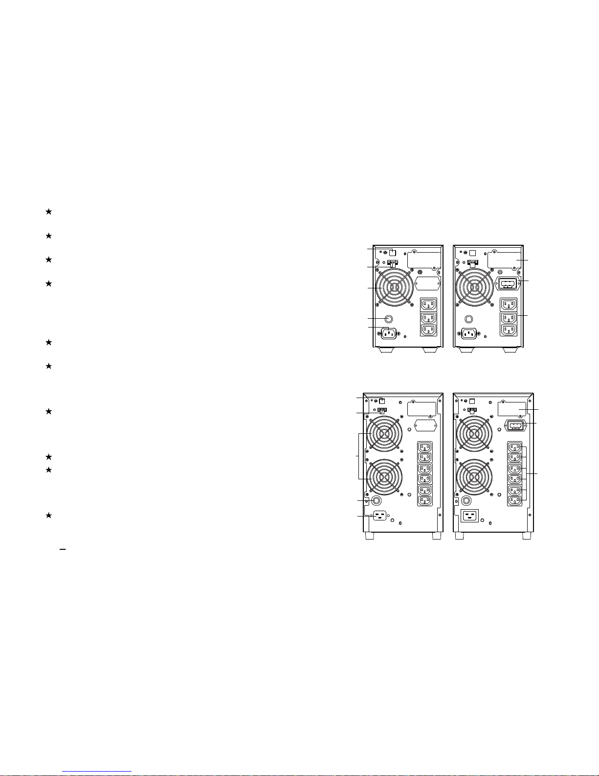
Appendix: Rear panel
Back View of 1K(L)
Back View of 2K(L)
Breaker
USB
EPO
Cooling Fan
Input Socket
Intelligent Slot
Batteryconnector
OutputSocket
Breaker
USB
EPO
CoolingFan
Input Socket
IntelligentSlot
Battery connector
Output Socket
-3-
Do not remove the enclosure. This system is to be serviced by
qualified service personnel only.
Remove the protective panel only after disconnecting the terminal
connections.
Use No. 12 AWG (for 2-3K/KL input wire) , 90¡C copper wire and
4.4 lb-in Torque force when connecting to terminal block.
Use No. 12AWG (for 2K/KL output wire) and No. 8AWG (for
3K/KL output wire), 90¡C copper wire and 12 lb-in Torque force
when connecting to terminal block.
1.3 Maintenance, servicing and faults
The UPS operates with hazardous voltages. Repairs may be
carried out only by qualified maintenance personnel.
Caution - risk of electric shock. Even after the unit is
disconnected from the mains power supply (building wiring
socket), components inside the UPS are still connected to the
battery which are potentially dangerous.
Before carrying out any kind of service and/or maintenance,
disconnect the batteries. Verify that no current is present and no
hazardous voltage exists in the capacitor or BUS capacitor
terminals.
Batteries must be replaced only by qualified personnel.
Caution - risk of electric shock. The battery circuit is not isolated
from the input voltage. Hazardous voltages may occur between
the battery terminals and the ground. Verify that no voltage is
present before servicing!
Batteries have a high short-circuit current and pose a risk of
shock. Take all precautionary measures specified below and
any other measures necessary when working with batteries:
remove all jewellery, wristwatches, rings and other metal
objects
Page 7
-4-
use only tools with insulated grips and handles.
When changing batteries, replace with the same quantity and the
same type of batteries.
Do not attempt to dispose of batteries by burning them. It could
cause explosion.
Do not open or destroy batteries. Effluent electrolyte can cause
injury to the skin and eyes. It may be toxic.
Please replace the fuse only by a fuse of the same type and of
the same amperage in order to avoid fire hazards.
Do not dismantle the UPS, except the qualified maintenance
personnel.
1.4 Transport
Please transport the UPS only in the original packaging (to
protect against shock and impact).
1.5 Storage
The UPS must be stockpiled in the room where it is ventilated
and dry.
-35-
12. Software
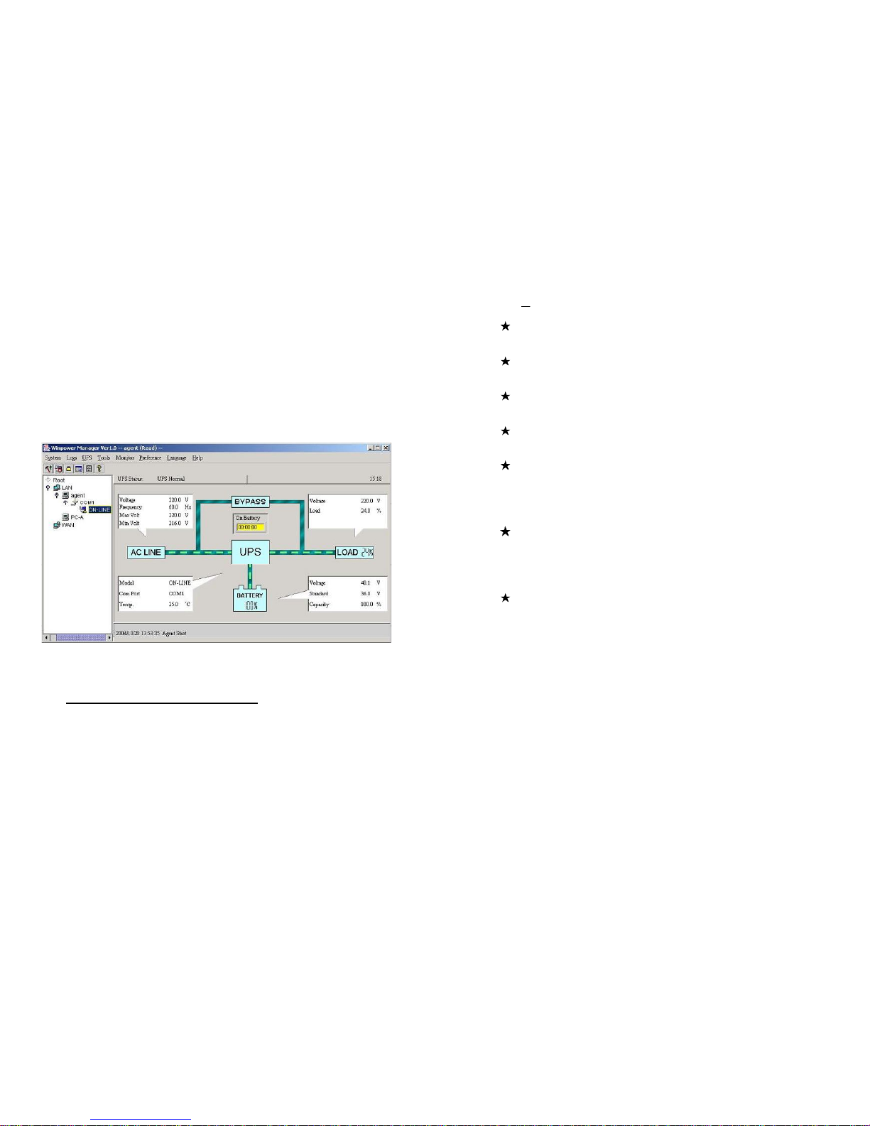
Free Software Download – WinPower
WinPower is a brand new UPS monitoring software, which provides
user-friendly interface to monitor and control your UPS. This unique
software provides safely auto shutdown for multi-computer systems while
power failure. With this software, users can monitor and control any UPS
on the same LAN no matter how far from the UPSs.
Installation procedure:
1. Go to the website:
http://www.ups-software-download.com/
2. Choose the operation system you need and follow the instruction
described on the website to download the software.
3. When downloading all required files from the internet, enter the serial
No: 511C1-01220-0100-478DF2A to install the software.
When your computer restarts, the WinPower software will appear as a
green plug icon located in the system tray, near the clock.
Page 8
-34-
11. Communication Port
The communication port is for the monitoring software. A USB port
and an intelligent slot are provided.
11.1 USB
The USB port is compliance with USB 1.1 protocol.
11.2 AS400 Interface (Option)
Except for the communication protocol as mentioned above, this
series UPS has AS400 card (an optional accessory) for AS400
communication protocol. Please contact your local distributor for
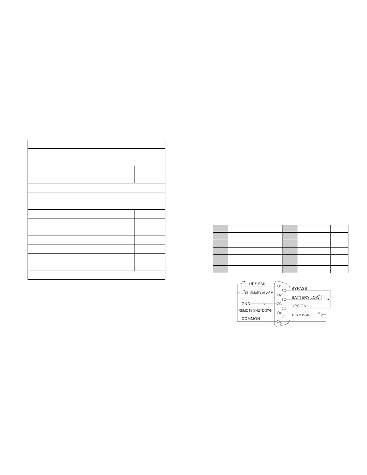
details. The following is the pin assignment and description of DB-9
connector in AS400 card.
Pin # Description I/O Pin # Description I/O
1 UPS Fail Output 6 Bypass Output
2 Summary Alarm Output 7 Battery Low Output
3 GND Input 8 UPS ON Output
4
Remote
Shutdown
Input 9 Line Loss Output
5 Common Input
DB-9 Interface of AS400 communication protocol
-5-
1.6 Standards
* Safety
IEC/EN 62040-1
* EMI
Conducted Emission.................................:IEC/EN 62040-2 Category C1
Radiated Emission....................................:IEC/EN 62040-2 Category C1
Harmonic Current....................................:IEC/EN 61000-3-2
Voltage Fluctuation and Flicker...............:IEC/EN 61000-3-3
*EMS
ESD........................................................:IEC/EN 61000-4-2 Level 4
RS..........................................................:IEC/EN 61000-4-3 Level 3
EFT.........................................................:IEC/EN 61000-4-4 Level 4
SURGE..................................................:IEC/EN 61000-4-5 Level 4
CS………………………………….....…...:IEC/EN 61000-4-6 Level 3
MS………………………………....……..: IEC/EN 61000-4-8 Level 3
Voltaje Dips………………………...…...: IEC/EN 61000-4-11
Low Frequency Signals..........................:IEC/EN 61000-2-2
Page 9
-6-
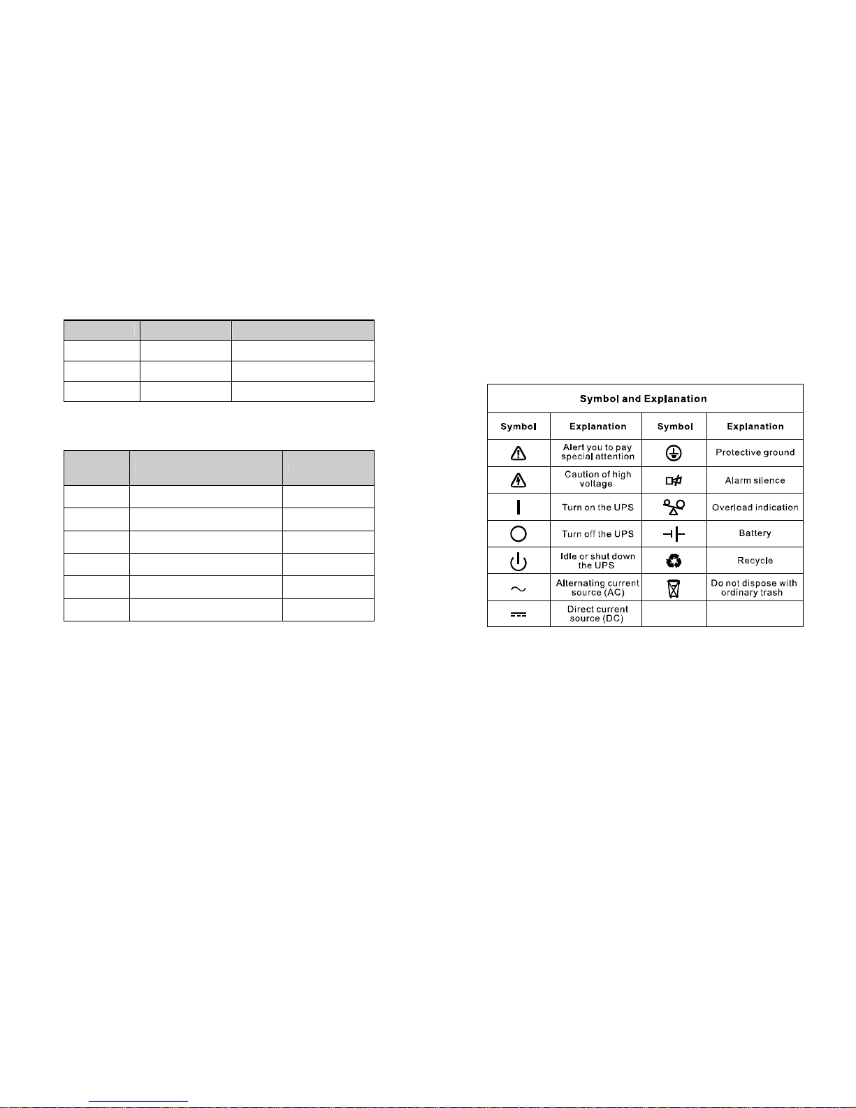
2. Description of Commonly Used Symbols
Some or all of the following symbols may be used in this manual. It is
advisable to familiarize yourself with them and understand their
meaning:
-33-
10.3 Typical backup time (Typical values at 25°C in minutes:)
Model No. 100 % Load 50 % Load
1K 5 14
2K 9 21
3K 5 15
10.4 Dimensions and weights
Model No. Dimensions W×D×H (mm) Net Weight (kg)
1K 145×400×220 13
1KL 145×400×220 7
2K 192×460×347 31
2KL 192×460×347 13
3K 192×460×347 31
3KL 192×460×347 13
Page 10
-32-
10. Technical Data
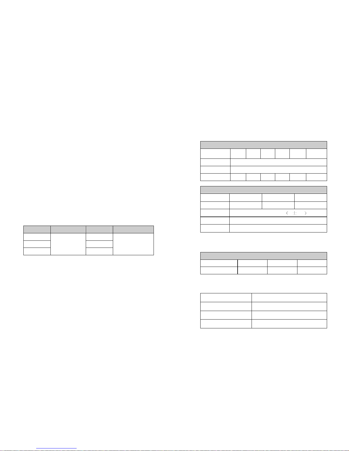
10.1 Electrical specifications
INPUT
Model No.
TAC-
HV1K
TAC-
HV1KL
TAC-
HV2K
TAC-
HV2KL
TAC-
HV3K
TAC-
HV3KL
Phase Single
Frequency (45~55)/(54~66) Hz
Current(A) 5A 7A 9A 14A 14.5A 18A
OUTPUT
Model No. 1K(L) 2K(L) 3K(L)
Power rating 1kVA/0.8kW 2kVA/1.6kW 3kVA/2.4kW
Voltage
200/208/220/230/240× 1 2% VAC
Frequency
50/60±0.2Hz (Battery mode)
Wave form sinusoidal
Derating to 90% when the output voltage is adjusted to 208VAC
Derating to 80% when the output voltage is adjusted to 200VAC
BATTERIES
Model No. 1K 2K 3K
Number and type 3×12V 7Ah 8×12V 7Ah 8×12V 7Ah
10.2 Operating Environment
Ambient Temperature 0 oC to 45 oC
Operating humidity < 95%
Altitude < 1000m
Storage temperature 0 oC to 45 oC
-7-
3. Introduction
This On-Line-Series is an uninterruptible power supply incorporating
double-converter technology. It provides perfect protection specifically
for Novell, Windows NT and UNIX servers.
The double-converter principle eliminates all mains power disturbances.
A rectifier converts the alternating current from the socket outlet to direct
current. This direct current charges the batteries and powers the
inverter. On the basis of this DC voltage, the inverter generates a
sinusoidal AC voltage, which permanently supplies the loads.
Computers and periphery are thus powered entirely by the mains
voltage. In the event of power failure, the maintenance-free batteries
power the inverter.
This manual covers the UPS listed as follows. Please confirm whether it
is the model you intend to purchase by performing a visual inspection of
the Model No. on the rear panel of the UPS.
“L” Model: Extended backup time
Model No. Type Model No. Type
1K 1KL
2K 2KL
3K
Standard
3KL
Extended backup
time
Page 11
-8-
4. Panel Description
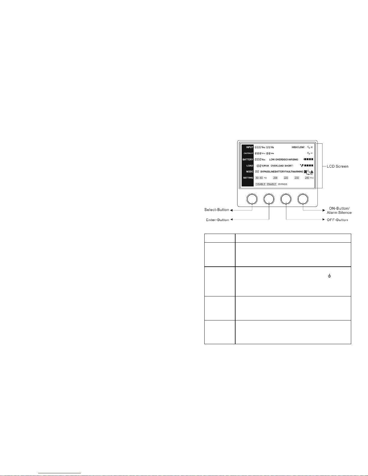
The Display Panel
Switch Function
ON-Button
Turn on UPS system:
By pressing the ON-Button “I” the UPS system is turned on.
Deactivate acoustic alarm:
By pressing this Button an acoustic alarm can be deactivated.
OFF-Button
When mains power is normal, the UPS system switches to No
output or Bypass mode by pressing OFF-Button “ “, and the
inverter is off. At this moment, if Bypass is enabled, then the
output sockets are supplied with voltage via the bypass if the
mains power is available.
Select-Button
If the UPS system is No output or Bypass mode, the output
voltage and frequency and Bypass disable/enable could be
selected by pressing Select-Button, and confirmed by pressing
Enter-Button.
Enter-Button
If the UPS system is No output or Bypass mode, the output
voltage and frequency and Bypass disable/enable could be
selected by pressing Select-Button, and confirmed by pressing
Enter-Button.
-31-
9. Maintenance
9.1 Operation
The UPS system contains no user-serviceable parts. If the battery
service life (3~5 years at 25°C ambient temperature) has been
exceeded, the batteries must be replaced. In this case please contact
your dealer.
9.2 Storage
If the batteries are stored in temperate climatic zones, they should be
charged every three months for 1~2 hours. You should shorten the
charging intervals to two months at locations subject to high
temperatures.
9.3 Battery Replace
If the battery service life has been exceeded, the batteries must be
replaced.
Battery replacement should be performed only by qualified personnel.
It recommends to shut off the UPS completely before the replacement.
If there is a battery breaker then turn it off first. Disconnect the battery
cable carefully and make sure no any exposed wires can be touched.
Reconnect the new batteries to the UPS by following section 5.8.
Then turn on the battery breaker and start the UPS.
If it needs to replace the batteries while the UPS is running, make
sure the UPS would not shut down during the replacement. If there is
a battery breaker then turn it off first. Disconnect the battery cable
carefully and make sure no any exposed wires can be touched.
Reconnect the new batteries to the UPS by following section 5.8.
Then turn on the battery breaker and press the ON switch to make the
UPS do the battery test, check whether the battery information is
normal.
Page 12
-30-
Please have the following information at hand before calling the
After-Sales Service Department:
1. Model number, serial number
2. Date on which the problem occurred
3. LCD display status, Buzzer alarm status
4. Utility power condition, load type and capacity, environment
temperature, ventilation condition
5. The information (battery capacity, quantity) of external battery pack
if the UPS is “L” model
6. Other information for complete description of the problem
-9-
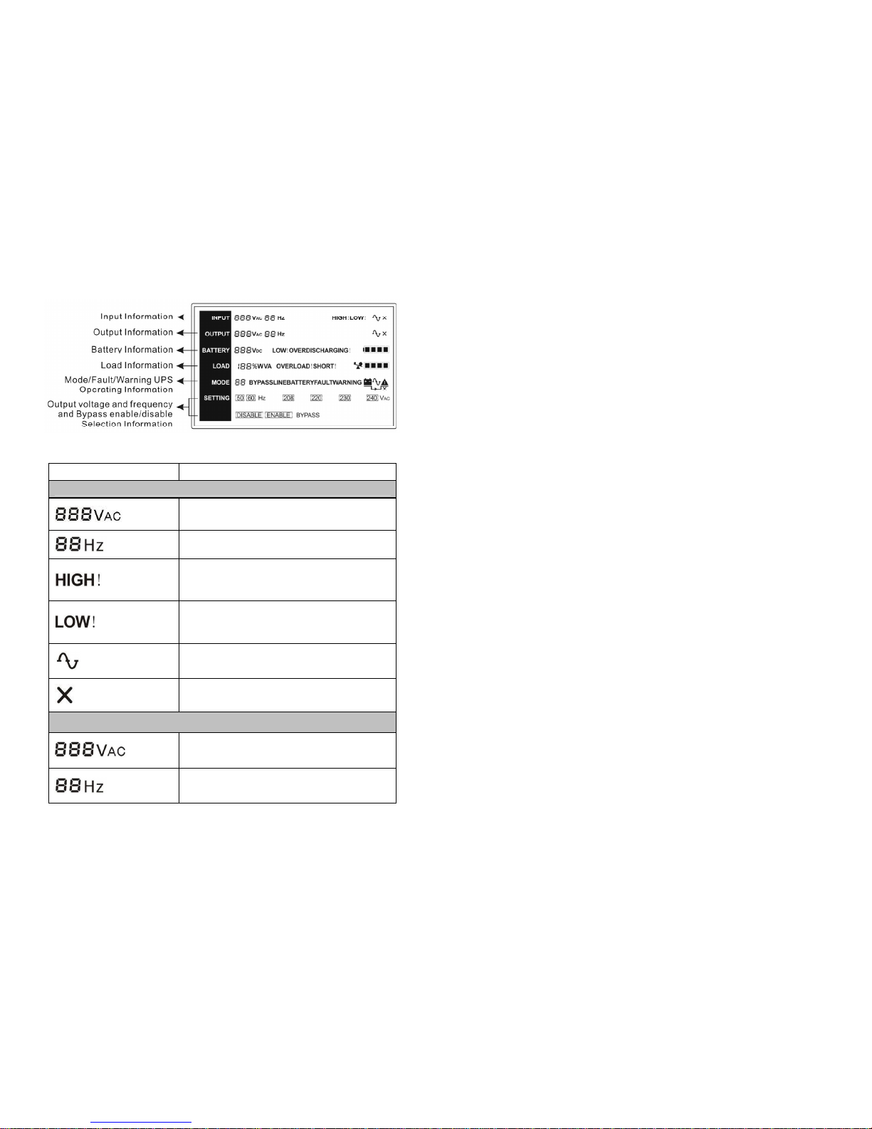
The LCD Display
Display Function
Input Information
Indicates the input Line voltage value, which could
be displayed from 0 to 999Vac
Indicates the frequency value of input Line
voltage, which could be displayed from 0 to 99Hz
Indicates the input Line voltage is higher than the
SPEC range, and the UPS would be working in
Battery mode
Indicates the input Line voltage is lower than the
SPEC range, and the UPS would be working in
Battery mode
Indicates the input power state, it would always be
displayed
Indicates the input power is off only if it is
displayed
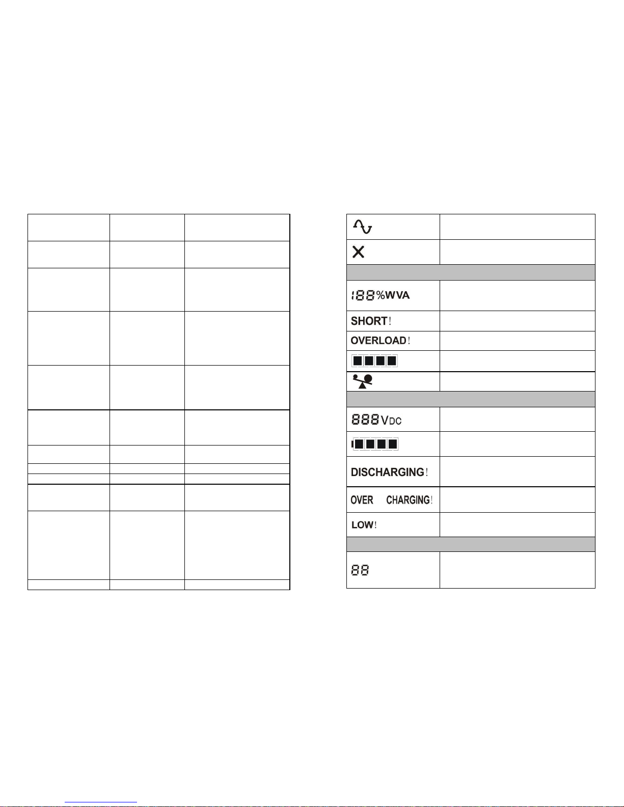
Output Information
(1)
Indicates the UPS output voltage value, which
could be displayed from 0 to 999Vac
Indicates the frequency value of the UPS output
voltage, which could be displayed from 0 to 99Hz
Page 13
-10-
Indicates the UPS output state, it would always be
displayed
Indicates the UPS output is shut off only if it is
displayed
Load Information
Indicates the load percent in Watt or VA, only the
maximum value of them could be displayed from 0
to 199%
Indicates the load or the UPS output is short and
the UPS would shut down
Indicates the load is over the SPEC range
Indicates the load percent, and every grid
represent 25% load.
Indicates the load is over the SPEC range
Battery Information
Indicates the battery voltage value, which could
be displayed from 0 to 999Vdc
Indicates the battery capacitance percent, and
every grid represent 25% capacitance.
Indicates the UPS is working in the battery mode,
and the battery is discharged for supplying the
load
Indicates the battery is over charged, and the
UPS would be switched to Battery mode
Indicates the battery is weak, and the UPS would
shut down soon
Mode/Fault/Warning UPS Operating Information
Indicates the operating mode of the UPS, Mode
code or Fault code or Warning code could be
displayed, and the codes are illuminated in detail
in the following chapter
-29-
Inverter temperature
high
Inside temperature
of the UPS is too
high
Check the ventilation of the
UPS, check the ambient
temperature.
Ambient temperature
high
The ambient
temperature is too
high
Check the environment
ventilation.
Line voltage high
(OVCD action)
Input power
voltage is too high
Switching to battery mode
automatically, and after the
mains is normal, the UPS
would Switching to line
mode automatically again.
Battery open
Battery pack is not
connected
correctly
Do the battery test to
confirm.
Check the battery bank is
connected to the UPS.
Check the battery breaker is
turn on.
Overload Overload
Check the loads and
remove some non-critical
loads.
Check whether some loads
are failed.
Site fail
Phase and neutral
conductor at input
of UPS system are
reversed
Rotate mains power socket
by 180° or connect UPS
system.
EPO active
EPO function is
enabled
Plug into the EPO switch.
Bus fault UPS internal fault Notify dealer
Inverter fault UPS internal fault Notify dealer
Over temperature
fault
Over temperature
Check the ventilation of the
UPS, check the ambient
temperature and ventilation.
Inverter short Output short circuit
Remove all the loads. Turn
off the UPS. Check whether
the output of UPS and loads
is short circuit. Make sure
the short circuit is removed,
and the UPS has no internal
faults before turning on
again.
Bus short UPS internal fault Notify dealer
Page 14
-28-
If the UPS system does not operate correctly, please attempt to solve the
problem using the table below.
Problem Possible cause Remedy
No indication, no
warning tone even
though system is
connected to mains
power supply
No input voltage
Check building wiring
socket outlet and input
cable.
Display Mode
code ”1” in LCD,
even though the
power supply is
available
Inverter not
switched on
Press On-Switch “I”.
Display Mode
code ”3” in LCD, and
audible alarm
sounding every 1
beep in every 4
seconds
Mains power
supply has failed,
or Input power
and/or frequency
are out of tolerance
Switching to battery mode
automatically.
Check input power source
and inform dealer if
necessary.
Emergency supply
period shorter than
nominal value
Batteries not fully
charged / batteries
defect
Charge the batteries for at
least
5 - 8 hours and then check
capacity. If the problem still
persists, consult your
dealer.
Fan fail Fan abnormal Check if the fan is running
Battery over voltage
Battery is over
charged
Switching to battery mode
automatically, and after the
battery voltage is normal
and the mains is normal, the
UPS would Switching to line
mode automatically again.
Battery low
Battery voltage is
low
When audible alarm
sounding every second,
battery is almost empty.
Charge fail
The charge is
broken
Notify dealer.
DC-DC temperature
high
Inside temperature
of the UPS is too
high
Check the ventilation of the
UPS, check the ambient
temperature.
-11-
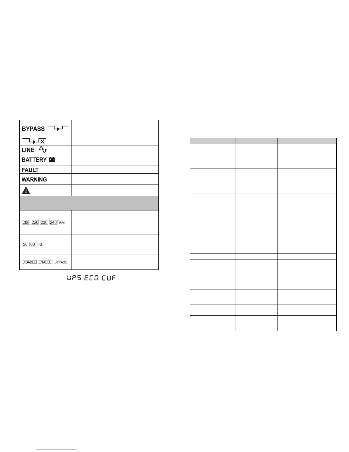
Indicates the UPS is working in bypass mode, the
load is directly supplied by the input power
through bypass
Indicates the UPS is working in no output mode
Indicates the UPS is working in line mode
Indicates the UPS is working in battery mode
Indicates the UPS is working in fault mode
Indicates some warnings occur which need be
attention
Indicates the UPS is abnormal in which some
faults or warnings occur
Output voltage and frequency and Bypass disable/enable
selection Information
The four value of the output voltage could be
selected when the UPS is in No output or Bypass
mode, and only one of them could be active in the
same time. Derating 10% when the output voltage
is adjusted to 208VAC
The two frequency value of the output voltage
could be selected when the UPS is in No output or
Bypass mode, and only one of them could be
active in the same time
Bypass disable or enable could be selected when
the UPS is in No output or Bypass mode, and only
one of them could be active in the same time
(1) Here would become , , instead when the user
does operating mode of UPS setting.
“UPS” means the setting of normal inverter mode (Line mode).
“ECO” means the setting of economy mode.
“CVF” means the setting of converter mode.
The detail illustration of the three modes and the operation of the
setting would be presented in the following section.
Page 15
-12-
5. Connection and Operation
5.1 Inspection:
Inspect the packaging carton and its contents for damage. Please
inform the transport agency immediately should you find signs of
damage.
Please keep the packaging in a safe place for future use.
Note: Please ensure that the incoming feeder is isolated and
secured to prevent it from being switched back on again.
5.2 Connection:
(1) UPS Input Connection
If the UPS is connected via the power cord, please use a proper
socket with protection against electric current, and pay attention to
the capacity of the socket: over 9A for 1K(L), over 17A for 2K(L),
over 26A for 3K(L). If the UPS is connected via wires, it is
recommended to select the 2.5mm2 wire, and the “GND” terminal
should be grounded first by using the green/yellow wire. The
wiring is shown as the following.
The UPS System has an input breaker on the cabinet. But we still
recommend users to connect an external breaker or protective
components to the input terminals. It is recommended to select the
NFB(Non-Fuse Breaker) instead of the traditional combination kit
including breaker and fuse."
When selecting the NFB, the user can refer to below table for
detailed information when installation.
The system may be installed and wired only by qualified
electricians in accordance with applicable safety regulations!
When installing the electrical wiring, please note the nominal
amperage of your incoming feeder.
-27-
8. Trouble Shooting
If the UPS system does not operate correctly, check the operating status on
the LCD display.
Normal operating mode Code
No output mode 0
Bypass mode 1
Line mode 2
Battery mode 3
Battery test mode 4
ECO mode 5
Converter mode 6
Warning Code
Site fail 09
Fan fail 10
Battery over voltage (over charged) 11
Battery low 12
Charge fail 13
DC-DC temperature high 21
Inverter temperature high 24
Ambient temperature high 25
Line voltage high (OVCD action) 26
Battery open 27
Overload 29
Fault Code
Bus fault 05
Inverter fault 06
Overload fault 07
Over temperature fault 08
Inverter short 14
Bus short 28
Page 16
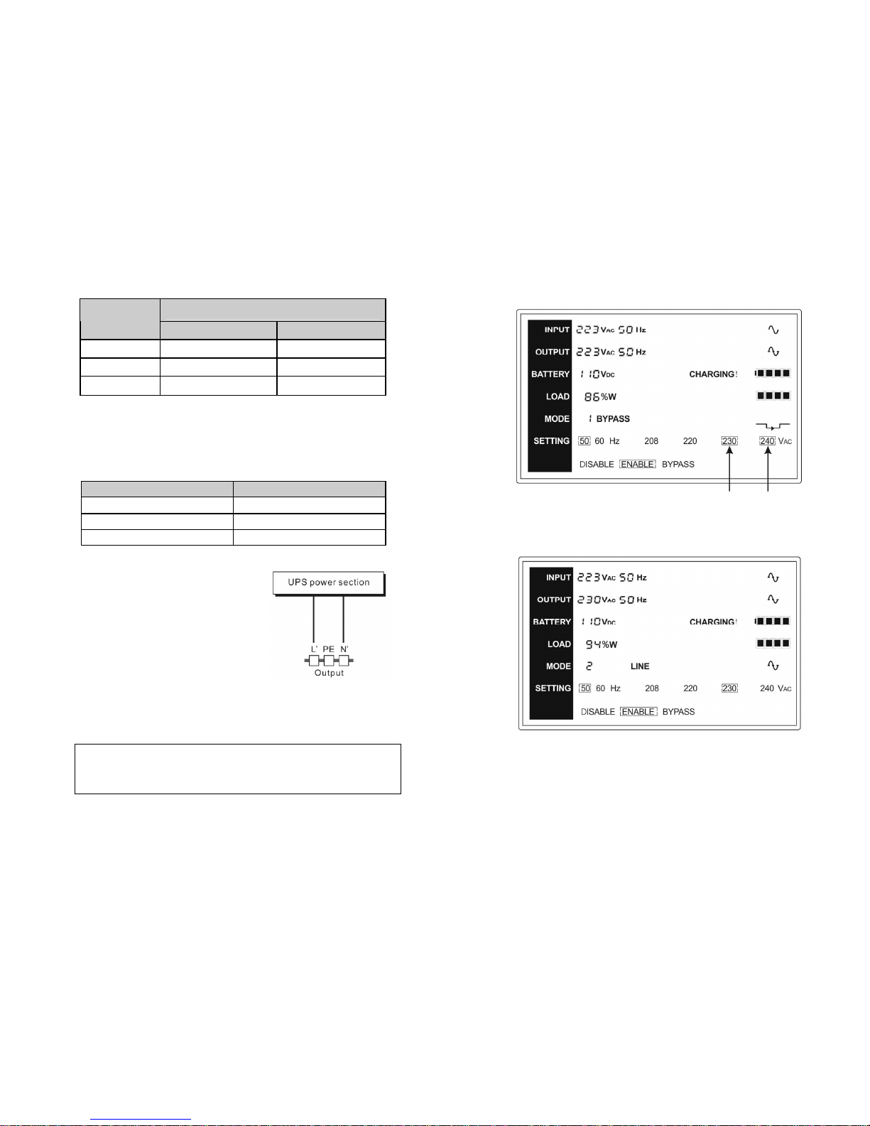
-26-
Setp 3:
The dot before “230Vac” would turn to flickerless
after pressing the “Enter” button.
Setp 4:
The output voltage would be 230Vac after the UPS is
turned on.
-13-
UPS INPUT NFB
Model No.
VOLTAGE CURRENT
1K(L) 300Vac 10A
2K(L) 300Vac 20A
3K(L) 300Vac 32A
(2) UPS Output Connection
The output of the UPS is US-type sockets. Simply plug the load
power cord to the output sockets to complete connection. Use one
cord for every 10A load.
Model No. Output Socket (pcs)
1K(L) 3 IEC-type
2K(L) 6 IEC-type
3K(L) 4 IEC-type
The wiring configuration is shown as
the following procedure:
a) Remove the small cover of the
terminal block.
b) Use 2.5mm2 wires for wiring
configuration.
c) Upon completion of the wiring
configuration, please check
whether the wires are securely
affixed.
d) Put the small cover back to the rear panel.
Caution!
Do not connect equipment which would overload the UPS
system (e.g. laser printers)
Connection diagram
Page 17
-14-
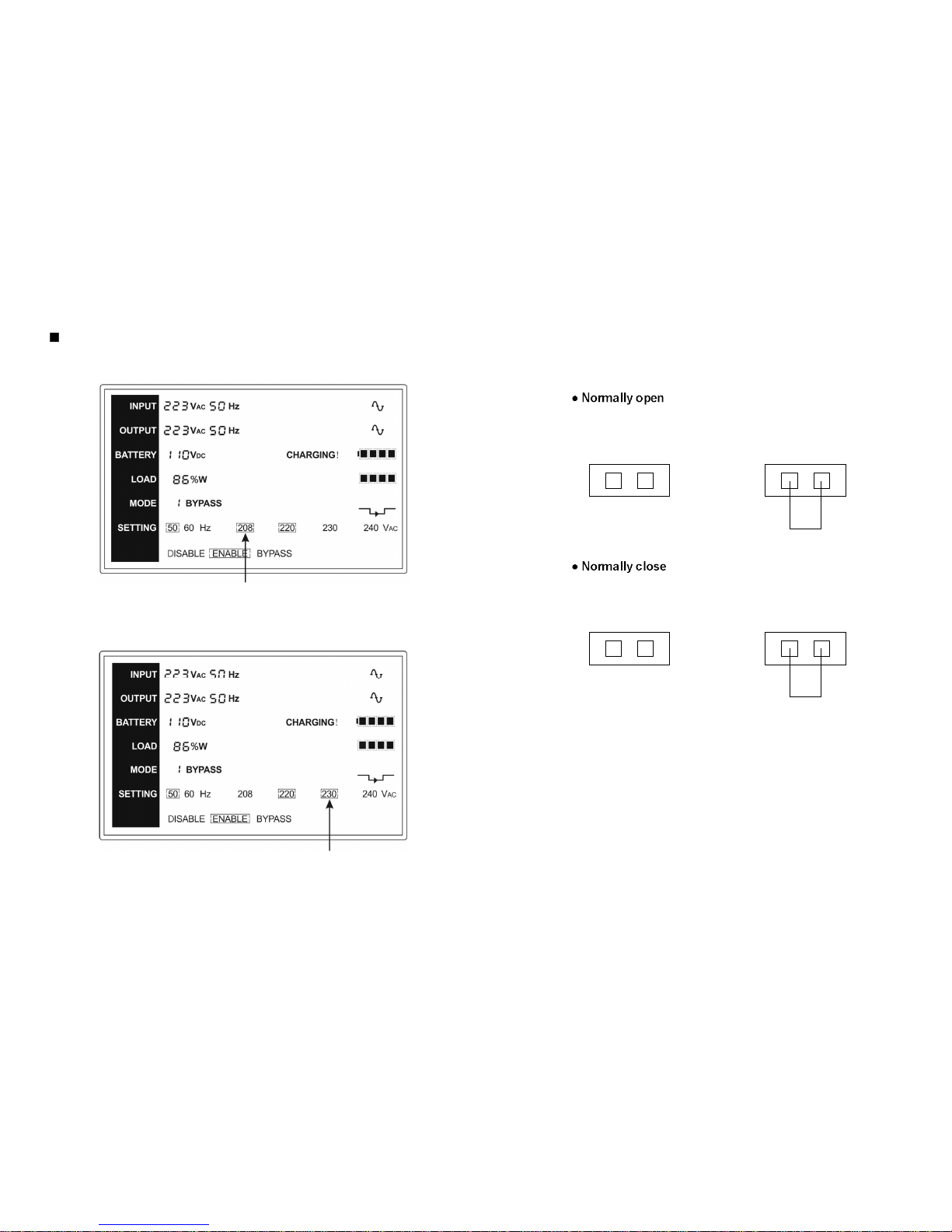
(3) EPO Connection:
User can select the polarity of EPO, EPO is Normally Close for
the UPS
Normally the EPO connector is open on the rear panel. Once the
connector is closed with a wire, the UPS would stop the output
until the EPO status is disabled.
Disable the EPO status Enable the EPO status
Normally the EPO connector is closed with a wire on the rear
panel. Once the connector is open, the UPS would stop the
output until the EPO status is disabled.
Enable the EPO status Disable the EPO status
5.3 Battery charge:
Fully charge the batteries of the UPS system by leaving the UPS
system connected to the mains for 1-2 hours. You may use the UPS
system directly without charging it but the stored energy time may be
shorter than the nominal value specified.
5.4 Turn on the UPS:
(1) With utility power connecting:
Press “I” button continuously for more than 1 second to turn on the
-25-
Here is a example for changing the output voltage from 220Vac to
230Vac through the LCD panel.
Setp 1:
One flickering black dot would appear before
“208Vac” after pressing the “Select” button.
Setp 2:
The flickering dot would move to “230Vac” after
pressing the “Select” button two times again.
Page 18

-24-
7. Setting by LCD Module
The output voltage and frequency, and bypass state, and ECO mode, and
Converter mode could be set directly through LCD module. The output
voltage could be set to 208V, 220V, 230V and 240V. The output frequency
could be set to 50Hz and 60Hz. The operating mode of UPS could be set
between the Line mode, ECO mode and Converter mode. The bypass
state could be set to enable and disable. But all the settings could only be
done when the UPS is in bypass or no output mode.
In bypass or no output mode, pressing the “Select” button on the LCD
panel for more than one second, a flickering black dot would be shown
before “208V” on the screen. And if pressing the “Select” button
continuously again, the flickering black dot would move to “220V”, next to
“230V”, “240V”, “50Hz”, “60Hz”, “Bypass Disable”, “Bypass Enable”,
“UPS”, “ECO”, “CVF” in turn. (Here “UPS” means the normal inverter
mode, and “UPS”, “ECO”, and “CVF” would be presented circularly at the
position of output voltage) And if pressing the “Enter” button for more than
one second at this time, the flickering black dot would turn to flickerless
and the output voltage or frequency or bypass state or mode state setting
would be modified to the selected value. And if no any pressing on the
“Select” or “Enter” button lasting for more than 30 seconds, the flickering
black dot would disappear.
The only one voltage value could be selected in “208V”, “220V”, “230V”,
“240V” at any time. The only one frequency value could be selected in
“50Hz”, “60Hz” at any time. And the output voltage and frequency would
be changed to the corresponding value after the right values are selected
on the LCD panel and the UPS is turn on by pressing the “ON” Button.
The UPS would turn to bypass mode in several seconds after “Bypass
Enable” is selected, and turn to no output mode in several seconds after
“Bypass Disable” is selected. The mode change would be active only after
the UPS is turned on.
-15-
UPS, the UPS will get into the inverter mode, the LCD screen will
indicate the state of the UPS.
(2) Without utility power connecting:
If UPS is cold start without utility power connecting, user need to
push “I” button twice, first pushing “I” button is for UPS to get
power, and second pushing “I” button continuously for more than 1
second is for UPS to turns on, the UPS will get into the inverter
mode. In fact, the two pushing “I” button is to make further sure
user operation for turning on UPS, the LCD screen will indicate the
state of the UPS.
Note: The default setting for bypass mode is no output after UPS
is connecting utility power and breaker is turned on. This can be
configured by monitoring the LCD panel or firmware.
5.5 Test function:
Test the function of the UPS system by pressing the On-Switch “I” for
more than 1 second, the UPS would detect whether the battery is
connected or the battery is low. And the UPS could also do the test
automatically and periodically, the period time could be set by user.
5.6 Turn off the UPS:
(1) In Inverter Mode:
Press “ “ button continuously for more than 1 second to turn off
the UPS, the UPS will get into no output or bypass mode. At this
time, the UPS might has output if bypass is enabled. Disconnect
the utility power to turn off the output.
(2) In Battery Mode:
Press “ “ button continuously for more than 1 second to turn off
the UPS, the UPS will be turned off completely.
Page 19

-16-
5.7 Audible alarm mute function:
If the alarm is too annoying in battery mode, you may press “I” button
continuously for more than 1 second to clear it. Moreover, the alarm
will be enabled when the battery is low to remind you to shutdown the
load soon.
If the alarm is too annoying in bypass mode, you may press “ “button
continuously for more than 1 second to clear it. The action doesn’t
affect the warning and fault alarm.
5.8 Operation procedure of external battery for long backup
time model (“L” model)
(1) Use the battery pack with voltage: 36VDC for 1KL (3 pcs of 12V
batteries), 96VDC for 2KL/ 3KL (8 pcs of 12V batteries).
Connection of batteries more than or less than required will cause
abnormality or permanent damage.
(2) One hard wiring type battery terminal on the rear panel is used for
connecting the battery pack.
(3) The battery connection procedure is very important. Any
incompliance may result in the risk of electric shock. Therefore,
the following steps must be strictly complied with.
(4) Make sure the mains input is cut off, if there is a battery breaker
then turn it off first.
(5) Remove the small cover of terminal block, prepare the battery
cable which should be able to carry the current of >30A for 1KVA,
>22A for 2KVA, >33A for 3KVA, the cross section area should be
great than 4 mm2 for all model. And battery wire color is
recommended as following:
GND
Red wire Green/Yellow wire Black wire
(6) The red wire is connected to the "+" terminal of the battery. The
-23-
2) It is attention that the transfer time of UPS output from ECO mode
to battery mode is less than 10ms. But it is still too long for some
sensitive load.
6.7 Converter mode
In converter mode, on LCD display, the mode code is “6”.
The UPS would free run with fixed output frequency (50Hz or 60Hz)
in converter mode. Once the mains is loss or abnormal, the UPS
would transfer to battery mode and the load is supplied continuously
by the battery.
1) It could be enabled through the LCD setting or the software
(Winpower, etc.).
2) The load should be derating to 60% in converter mode.
6.8 Abnormal mode
In abnormal mode such as Bus fault etc., the corresponding fault
code would be shown to indicate the operating mode of the UPS.
And some warning words could also be shown, for example “short!”
would be shown when the load or the UPS output is short and the
UPS is in inverter fault mode.
Page 20
-22-
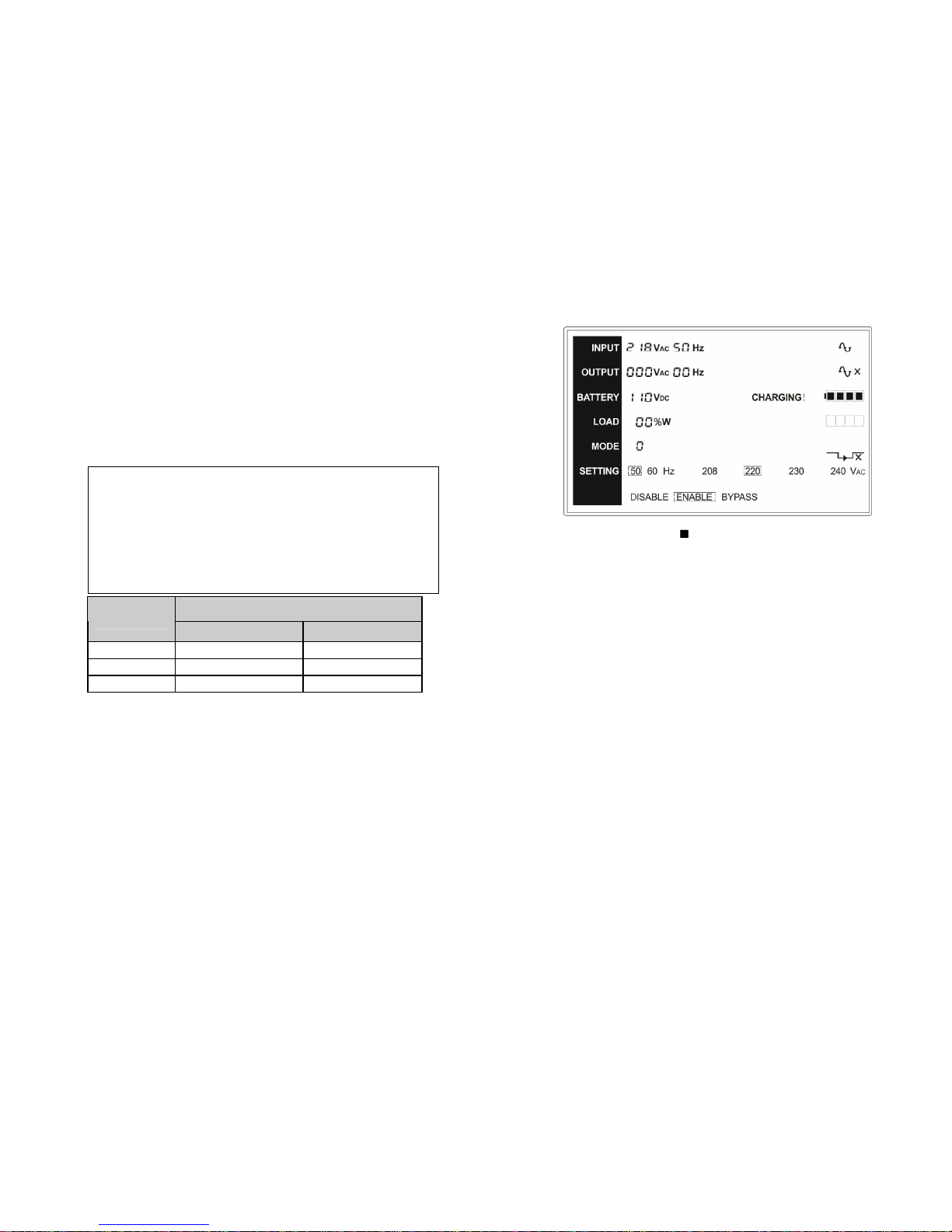
6.5 EPO (Emergency Power Off)
It is also called RPO (Remote Power Off). On LCD display, the mode
code is “0”, the word of “EPO” are presented in the position of output
voltage.
It is a special status in which the UPS would shut the output off and
alarm. The UPS could not be turned off by pressing “OFF” button on
the panel, only after releasing EPO status by Plugging into the EPO
switch.
6.6 ECO mode (Economy mode)
It is also called high efficiency mode. In ECO mode, on LCD display,
the mode code is “5”.
After the UPS is turned on, the power used by the load is supplied
from the utility power via internal filter while the utility power is in
normal range, so the high efficiency could be gained in the ECO
mode. Once the mains is loss or abnormal, the UPS would transfer to
battery mode and the load is supplied continuously by the battery.
1) It could be enabled through the LCD setting or the software
(Winpower, etc.).
The No output mode
-17-
black wire is connected to the "-" terminal of the battery. (Note:
the green/yellow wire is grounded for protection purpose.)
(7) Make sure the wires are fasten, install the terminal block cover on
the rear panel of the UPS.
(8) Connect the UPS to the load. Then, turn on the mains switch or
connect the power cord of the UPS to utility power supply, the
battery would start to be charged.
DC breaker
Model No.
VOLTAGE CURRENT
1KL 48Vac 50A
2KL 125Vdc 40A
3KL 125Vdc 60A
The Caution!
A DC breaker must be connected between the UPS and
external battery.
The Caution!
The output sockets of the UPS system may still be electrically
live even if the power supply system has been disconnected or
the Bypass switch is on “OFF” position.
Page 21
-18-
6. Operating Mode for All Models
The different codes could be displayed on the LCD screen
corresponding to their own operating modes, and they are illustrated
as the following table. At any time, only one normal operating mode
or fault mode is presented. But the warning, even several warnings
could appear in a certain normal operating mode at one time. And
the normal operating mode code and the warning code would be
shown circularly. Once one fault is come forth, then all previous
warnings would not be shown again but only the fault code is
presented.
Normal operating mode Code
No output mode 0
Bypass mode 1
Line mode 2
Battery mode 3
Battery test mode 4
ECO mode 5
Converter mode 6
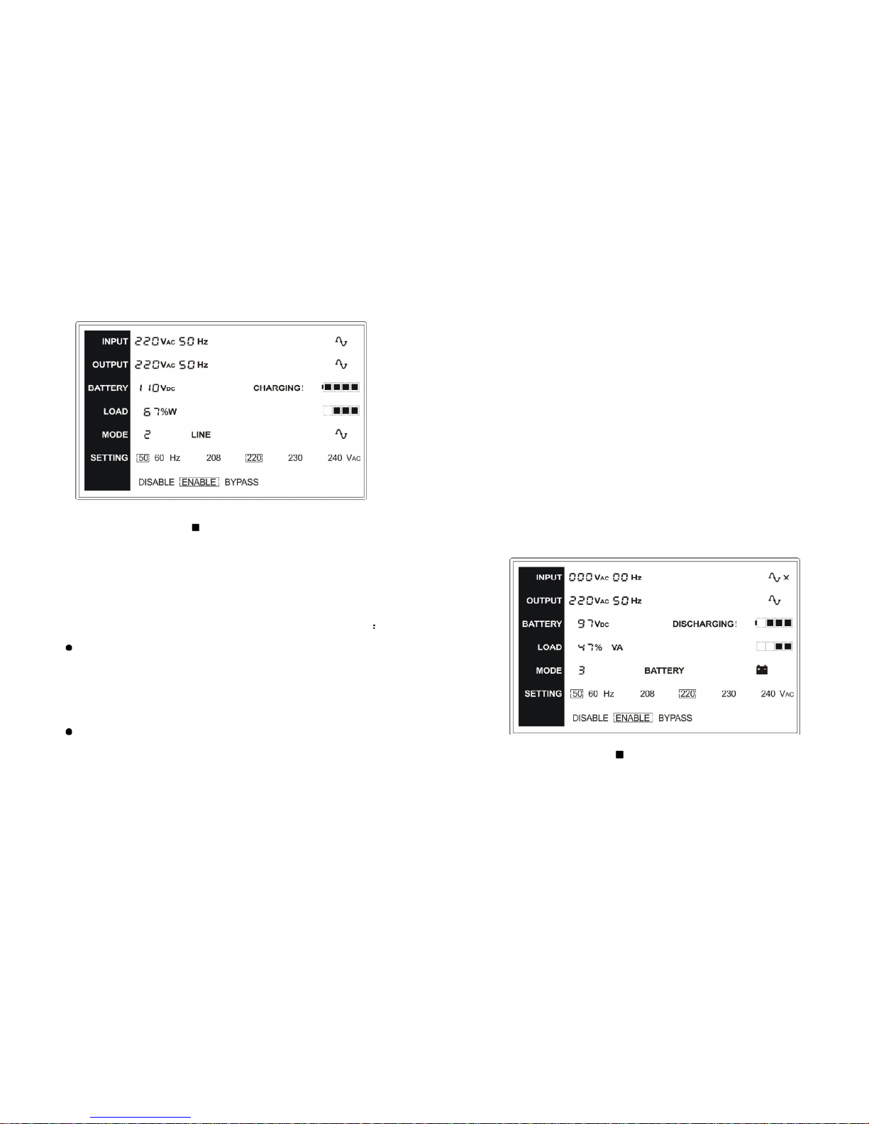
6.1 Line mode
The LCD display in Line mode is shown in the following diagram. The
information about the utility power, the battery, the UPS output and
the load could be displayed. The word of “LINE” indicates the
inverter of the UPS is working. The operating mode code of the UPS
is “2”.
-21-
battery mode code of the UPS is “3”, and the battery test mode code
is “4”.
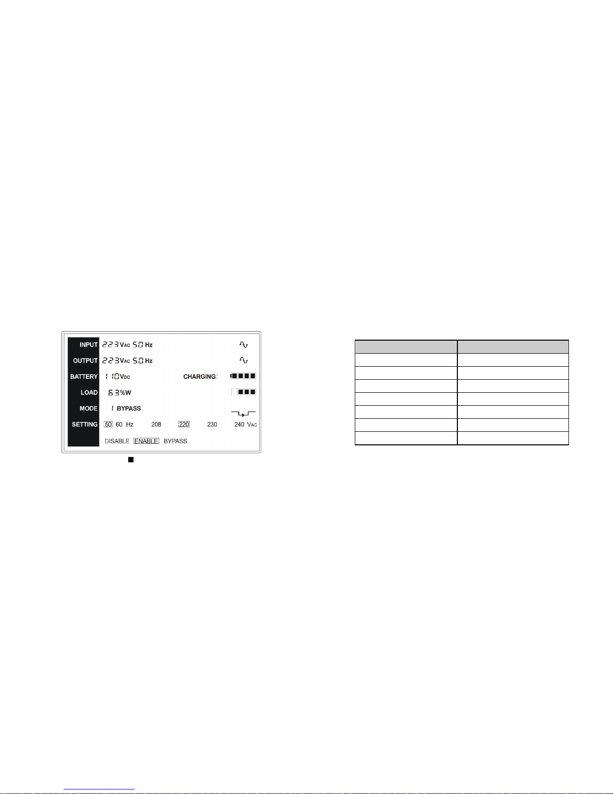
6.3 Bypass mode
The LCD display in bypass mode is shown in the following diagram.
The information about the utility power, the battery, the UPS output
and the load could be displayed. The UPS will beep once every 2
minutes in bypass mode. The word of “BYPASS” indicates the
bypass of the UPS is working. The bypass mode code of the UPS is
“1”.
The UPS does not have the backup function when it is in bypass
mode. The power used by the load is supplied from the utility power
via internal filter.
6.4 NO output mode
The LCD display in No output mode is shown in the following
diagram. The information about the utility power, the battery, the UPS
output and the load could be displayed. The “0” code indicates the
UPS is working in the No output mode.
The Bypass mode
Page 22
-20-
and the load could be displayed. The block of “BATTERY” indicates
the inverter of the UPS is working.
1) When the UPS is running in battery mode, the buzzer beeps once
every 4 seconds. If the “ON” button on the front panel is pressed
for more than 1 second again, the buzzer will stop beeping (in
silence mode). Press the “ON” button once again for more than 1
second to resume the alarm function.
2) If the UPS is working in battery mode for the input line voltage is
higher than the SPEC range, the alarm symbol - “High!” will be
shown; if the UPS is working in battery mode for the input line
voltage is lower than the SPEC range, the alarm symbol - “Low!”
will be shown; if the input line voltage is lost, both “High!” and
“Low!” would not be shown but the input voltage and frequency are
shown as zero.
The display of battery test mode is same as battery mode, but “High!”
and “Low!” would not be shown unless the input line voltage is higher
or lower than the SPEC range during the time of battery test. The
The Battery mode
-19-
If output overloaded, the load percent is shown and alarm will keep
twice every second. You should get rid of some unnecessary loads
one by one to decrease the loads connected to the UPS less than
90% of its nominal power capacity.
Note: Please follow the following steps to connect the generator
Activate the generator and wait until the operation is stable before
supplying power of the generator to the UPS (be sure that the UPS
is in idle mode). Then turn on the UPS according to the start-up
procedure. After the UPS is turned on, then the loads can be
connected to the UPS one by one.
The power capacity of the AC generator should be at least twice of
the UPS capacity.
6.2 Battery mode
The LCD display in battery mode is shown in the following diagram.
The information about the utility power, the battery, the UPS output
The Line mode
 Loading...