

Page 1
U-UDS5000WD Drawing Table Assembly Instructions
Additional Tools needed: Phiillips Screwdriver
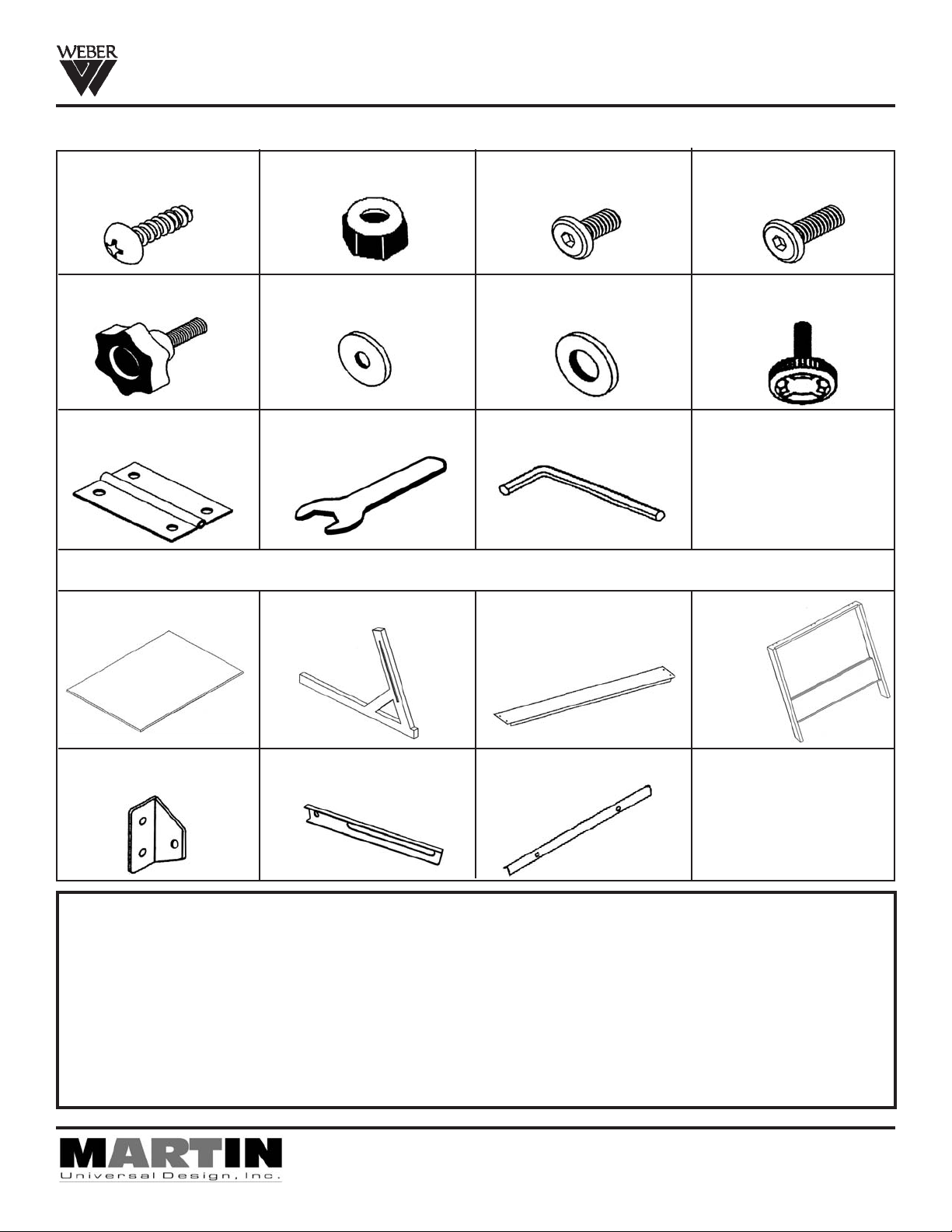
Hardware List
[1] - M4x12mm Screws
(18 each)
[5] - Knobs - Male
(4 each)
[9] - Hinge
(4 each)
[6] - Washer with small
[2] - Nuts
(2 each)
hole (4 each)
[10] - Wrench
(1 each)
[3] - M6x8mm Allen
Screw (4 each)
[7] - Washer with large
hole (4 each)
[11] - Allen-Wrench
(1 each)
Parts List
[A] - Table Top (1 each) [B] - Base foot (2 each) [C] - Foot Rest Cross
Support (1 each)
[4] - M6x12mm Allen
Screw (2 each)
[8] - Threaded Rubber
Feet (4 each)
[D] - H-Frame
Support
(1 each)
[E] - Tilt Bracket End
(2 each)
[F] - Tilt Bracket (2 each) [G] - Pencil Edge
IMPORTANT
If you have difficulty assembling your U-DS5000WD Table
or need customer service assistance.
Please call:
Martin Universal Design, Inc. Customer Service Hot Line at
1-313-895-0700.
If you need additional parts,
it is not necessary to contact your dealer
to you immediately.
4444 Lawton Avenue, Detroit, MI 48208 USA • Tel:(313)895-0700/Fax:(313)895-0709
Email: Custservmud@aol.com • visit us at www.MartinUniversalDesign.com
(1 each)
, our Customer Service Rep. will forward them
Pg. 1
Aug. 08 Revised- RPI
Page 2
U-UDS5000WD Drawing Table Assembly Instructions
IMPORTANT: ASSEMBLY IS EASIER AND SAFER WITH TWO PEOPLE
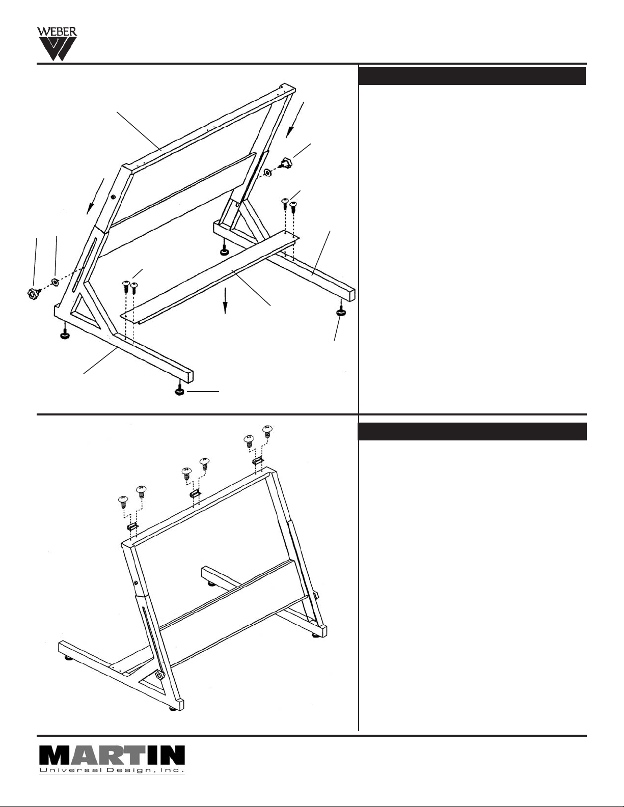
STEP 1] Assembly Base of Table
Begin by taking the [2] Lower Base Feet (part B)
D
5
1
and attach the foot rest (part C) to the Lower Base
Feet using [2] M4 x 12mm screws (part 1). Secure
by tightening screws. See FIG 1.
Continue by sliding the H-Frame (part D) down
into the sides of the Lower Base Feet (part B).
Secure with large washer (part 7) and Knob (part
5). Tighten Knob to secure.
5
FIG 1
7
B
Complete Step 1 by inserting [4] Threaded Rubber
Feet (part 8) into the bottom of the base.
See FIG 1.
1
C
8
B
8
STEP 2] Hinges to Base Assembly
Attach [3] Hinges (part 9) to the top edge of the
H-Frame (part D) by using [2] M4 x 12mm screws
in each hinge as shown in FIG 2.
Secure to H-Frame with Phillips screw-driver.
FIG 2
Pg. 2
4444 Lawton Avenue, Detroit, MI 48208 USA • Tel:(313)895-0700/Fax:(313)895-0709
Email: Custservmud@aol.com • visit us at www.MartinUniversalDesign.com
Aug. 08 Revised- RPI
Page 3

U-UDS5000WD Drawing Table Assembly Instructions
IMPORTANT: ASSEMBLY IS EASIER AND SAFER WITH TWO PEOPLE
FIG 3
A
G
3
4
6
2
3
STEP 3] Tilt Bracket Assembly
Lay table top onto flat carpeted or cardboard surface with holes facing up (to protect from scratching
table top). Attach the Tilt Bracket End (part E) to the
table top in the position as shown in FIG 3 using [2]
each M6 x 8mm Allen Screws (part 3) per bracket.
Line up holes in bracket end with T-nuts in table
top. Secure with Allen-Wrench. See FIG 3.
6
F
Continue by adding Tilt Bracket (part F) to tilt
E
bracket end (part E) securing with [1] M6 x 12mm
Allen-Screw (part 4), [2] washers (part 6) and [1]
Nut (part 2). Tighten with Allen-Wrench to secure.
See FIG 3.
4
E
STEP 4] Assembling Top to Base
1
IMPORTANT:
THIS NEXT STEP NEEDS TWO PEOPLE TO
5
Attach Top to base by having one person hold the
F
top while the other person attaches the hinges
that are on the table base to the top using [2] M4
x 12mm screws (part 1) in each hinge. Tighten
with Phillips screw-driver to secure.
ATTACH TOP TO BASE.
FIG 4
Attach pencil ledge to the front edge of table top
using [2] each M4 x 12mm Screws (part 1). Secure
1
with Phillips screw-driver.
Attach Tilt brackets to table base using [1] Knob
(part 5) and [1] washer (part 7). Tighten knob to
secure. Repeat with other side.
See Fig 4B.
7
H
5
FIG 4B
Pg. 3
Pg. 3
4444 Lawton Avenue, Detroit, MI 48208 USA • Tel:(313)895-0700/Fax:(313)895-0709
Email: Custservmud@aol.com • visit us at www.MartinUniversalDesign.com
Aug. 08 Revised- RPI
Page 4

U-UDS5000WD Drawing Table Assembly Instructions
IMPORTANT: ASSEMBLY IS EASIER AND SAFER WITH TWO PEOPLE
STEP 5] Table Adjustments
To Raise or Lower the height of the table, loosen the Lower knobs found on the channeled Base supports. Raise or Lower
the table to your desired position and re-tighten the knobs to secure. See illustration below.
To Adjust the tilt of your table, loosen the knobs found on the tilt brackets. Loosen and change the tilt of the table top, retighten once desired tilt is achieved. See illustration below.
If your table seems like it is uneven due to an un-even floor. Loosen or tighten each rubber foot until the table sits evenly
on the surface. See illustration below.
NOTE: The back of the table has a convenient Book Shelf/Ledge which holds books and magazines.
ENJOY your new MXZ Drawing Table!
These upper knobs
are for table
tilt adjustment
These lower knobs
are for table
height adjustment
The Rubber Feet
can be adjusted for
uneven floors.
The back of the table has a convenient
Book Shelf/Ledge which holds books
and magazines.
Pg. 4
Aug. 08 Revised- RPI
4444 Lawton Avenue, Detroit, MI 48208 USA • Tel:(313)895-0700/Fax:(313)895-0709
Email: Custservmud@aol.com • visit us at www.MartinUniversalDesign.com
 Loading...