

Page 1
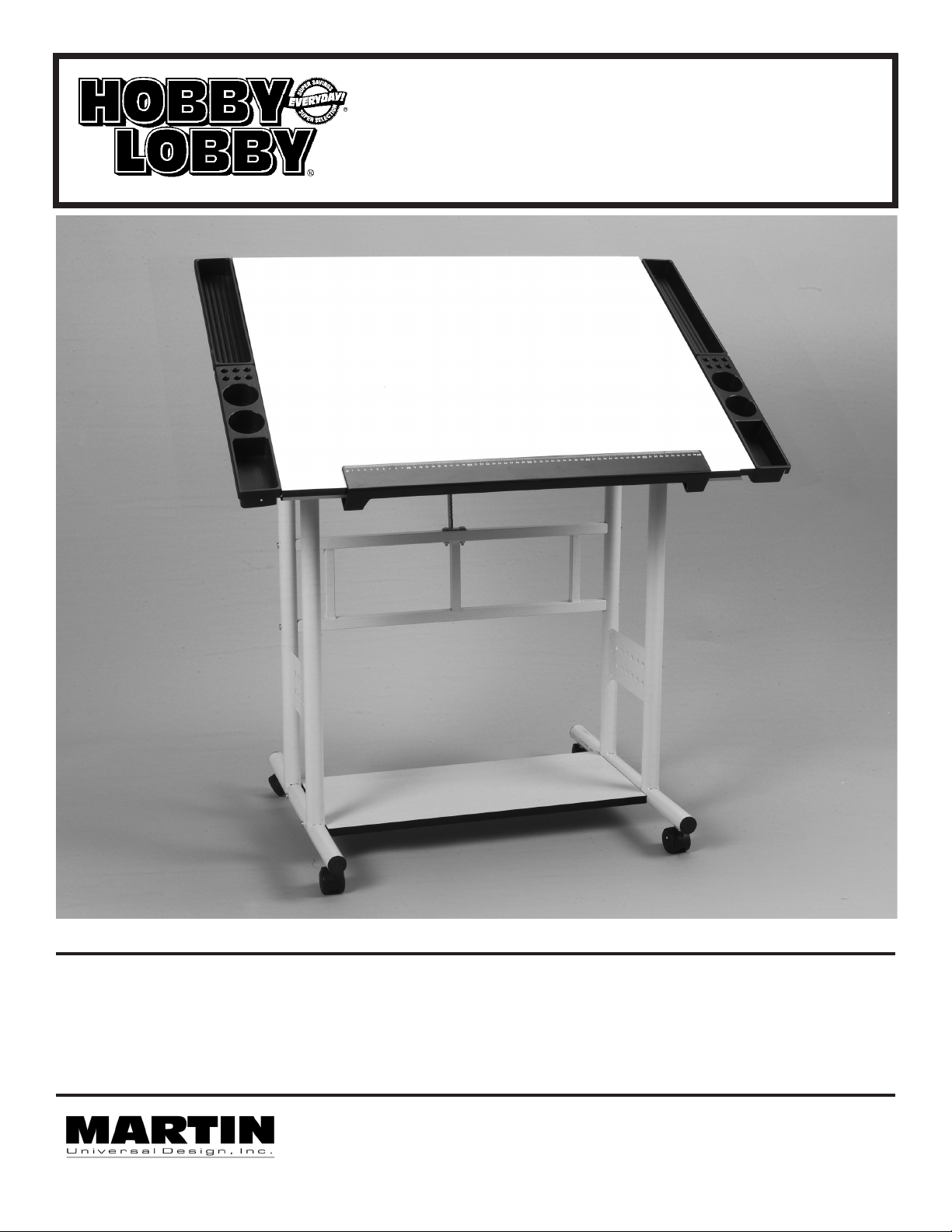
Ariel Table
Assembly Instructions
Model No. U-HL6080W
UPC 080031055002
IMPORTANT
If you have difculty assembling your Ariel Table - MODEL # U-HL6080W
or need customer service assistance. Please call:
Martin Universal Design, Inc. Customer Service Hot Line at 1-313-895-0700.
If you need additional parts, it is not necessary to contact your dealer,
our Customer Service Rep. will forward them to you immediately.
Martin Universal Design, Inc. • Detroit, MI 48208 USA
Tel: 1-313-895-0700 • E-mail: custservmud@gmail.com
www.MartinUniversalDesign.com • Made in China
2/28/11- RPI
Page 2
Ariel Table
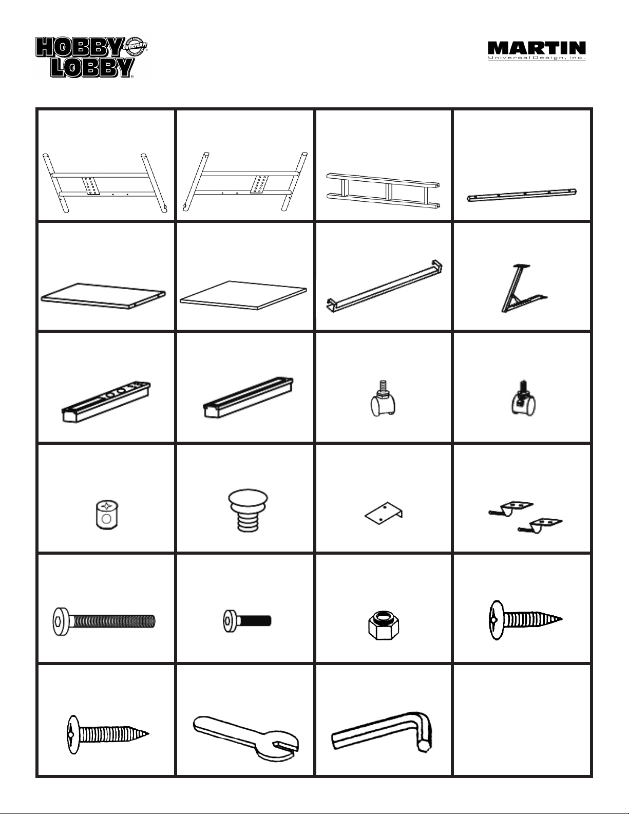
Hardware Parts List
Part A.
1 ea. Left Leg
Part E.
1 ea. Base Shelf
Part I.
2 ea. Side Tray A
Part B.
1 ea. Right Leg
Part F.
1 ea. Table Top
Part J.
2 ea. Side Tray B
Part C.
1 ea. Cross Support
Part G.
1 ea. Ruler
Part K.
2 ea. Castors
Part D.
1 ea. Ruler Support
Bar
Part H.
1 ea. Tilt Mechanism
Part L.
2 ea. Locking Castors
Part M.
4 ea. CAM Locks
Part Q.
8 ea. 6x55mm Hex
Part U.
3 ea. 4x35mm Hex
Part N.
2 ea. Plastic Caps
Part R.
2 ea. 6x30mm Hex
Part V.
1 ea. Wrench
Part O.
8 ea. Side Tray Clips
Part S.
2 ea. Nylon Nuts
Part W.
1 ea. Allen Wrench
Part P.
2 ea. Top Brackets
Part T.
22 ea. 5x14mm screws
2
2/28/11- RPI
Page 3

Ariel Table Assembly Instructions:
Step 1. Attach Castors to Left and Right
Legs
Insert 1 ea. Locking Castor (Part L) into
each of the two front holes found on
the bottom of each leg (Part A & B)
B
A
K
Insert 1 ea. Castor (Part K) into each of
the two rear holes found on the bottom
of each leg (Part A & B)
See FIG 1
Step 2. Insert Cam Locks into Base
Shelf
Insert 4 ea. Cam Locks (Part M) into
each of the holes found on the bottom
side of the Base Shelf (Part E), making
sure holes line up with holes in shelf
edge.
See FIG 2
Step 3. Attach Cross Member to ea. leg.
Attach Cross Member (Part C) to each
leg using 2 each Hex Bolts (Part Q).
Thread the Hex bolt through the side
of each leg and into the cross member
holes.
DO NOT TIGHTEN at this point, keep
the bolts slightly loose.
See FIG 3
Q
L
M
L
FIG 1
E
FIG 2
Q
C
FIG 3
Step 3B. Attach Base Shelf to Base
Attach White Base Shelf (Part E) to
base using 2 each Hex Bolts (Part Q) in
each end of Shelf. TIGHTEN using
Allen Wrench (Part W). Repeat with
other side. See FIG 3B
NOW go back and TIGHTEN CROSS
MEMBER HEX BOLTS (STEP 2) with
Allen Wrench (Part W).
Martin Universal Design, Inc. • Detroit, MI 48208 USA
Tel: 1-313-895-0700 • E-mail: custservmud@gmail.com • www.MartinUniversalDesign.com
Q
E
Q
FIG 3B
3
2/28/11- RPI
Page 4

Ariel Table Assembly Instructions:
Step 4. Attach Table Top Tilt Mechanism
Attach Tilt Mechanism (part H) to Cross
member (part C) in position as seen in
FIG 4.
Secure by using 2 ea. Hex Bolts
(part R) and 2 ea. Nylon Nuts (part S).
Tighten to secure with supplied wrench
(part W)
See FIG 4
Step 5. Attach Ruler Support Bar
Begin by laying Table Top (part F) face
down on protected hard oor (like a
carpeted oor).
Attach Ruler Support Bar (part D) to
bottom of table top by lining up
Support Bar to the pre-drilled holes
in the table top. Secure using 3 wood
screws (part U). Insert 2 each plastic
caps into the holes on either end of the
ruler support bar.
See FIG 5.
H
C
REAR
END OF TABLE
F
S
R
N
FRONT
END OF
TABLE
FIG 4
D
N
U
FIG 5
Step 5B. Attach Side Tray Metal Clips
Line up all 8 Metal Side Tray Clips (part
O) to each hole in the top and secure
each one to the table top using 2 ea.
wood screws (part T) per metal support.
PLEASE NOTE: The lip on the Metal
Side Tray Supports should wrap around
the side edge of the table top.
See FIG 5B.
Martin Universal Design, Inc. • Detroit, MI 48208 USA
Tel: 1-313-895-0700 • E-mail: custservmud@gmail.com • www.MartinUniversalDesign.com
O
Lip of Metal
T
Tray Clips
positioned
around
edge of top
F
FIG 5B
4
2/28/11- RPI
Page 5

Ariel Table Assembly Instructions:
Step 6. Attach Ruler to Ruler Support
Bar
Clip/Snap Ruler (part G) onto
Ruler Support Bar (Part D).
See FIG 6.
Step 7. Attach Table Top Brackets
Attach 1 ea. Table Top Brackets
(part P) to each left & right leg by
inserting bracket rod into hole found on
inside edge of the legs top support bar.
See FIG 7.
G
FIG 6
RULER
P
Step 8. Attach Table Top to
Base Assembly
Line up holes in table top (part F) with
Table Top Metal Brackets (part P)
located on each leg’s top support bar.
Secure using 2 ea. Wood Screws
(part T). Tighten to secure.
See FIG 8
Continue by attaching Tilt Mechanism
(part H) to table top by lining up holes
in tilt mechanism to holes in table top
and securing with 2 ea. Wood screws
(part T). Tighten to secure.
See FIG 8
FIG 7
T
H
T
T
FIG 8
Martin Universal Design, Inc. • Detroit, MI 48208 USA
Tel: 1-313-895-0700 • E-mail: custservmud@gmail.com • www.MartinUniversalDesign.com
5
2/28/11- RPI
Page 6

Ariel Table Assembly Instructions:
Step 9. Assembling 2 Side Trays into
one long tray. (Optional)
If you would like one long side tray,
you must clipp 2 Side Trays (part I & J)
together as shown in FIG 9.
OPTIONAL CHOICES:
If you would like to use two of the same
Side Trays together you may.
As shown in FIG 9B and 9C
Step 10. Attach Side Trays to Table Top
To attach the side trays (parts I & J) to
the table top, slide the side trays down
onto the brackets making sure the side
tray edge ts onto the metal brackets.
See FIG 10.
I
OR OR
I
I
FIG 9B FIG 9C
J
I
J
J
FIG 9
J
J
I
FIG 10
Step 11. COMPLETING ASSEMBLY
Go back and make sure all screws and bolts are tight,
Once complete, your Ariel Table is now ready for your enjoyment!
Martin Universal Design, Inc. • Detroit, MI 48208 USA • Tel: 1-313-895-0700
E-mail: custservmud@gmail.com • www.MartinUniversalDesign.com • Made in China
6
2/28/11- RPI
O
 Loading...