

Page 1
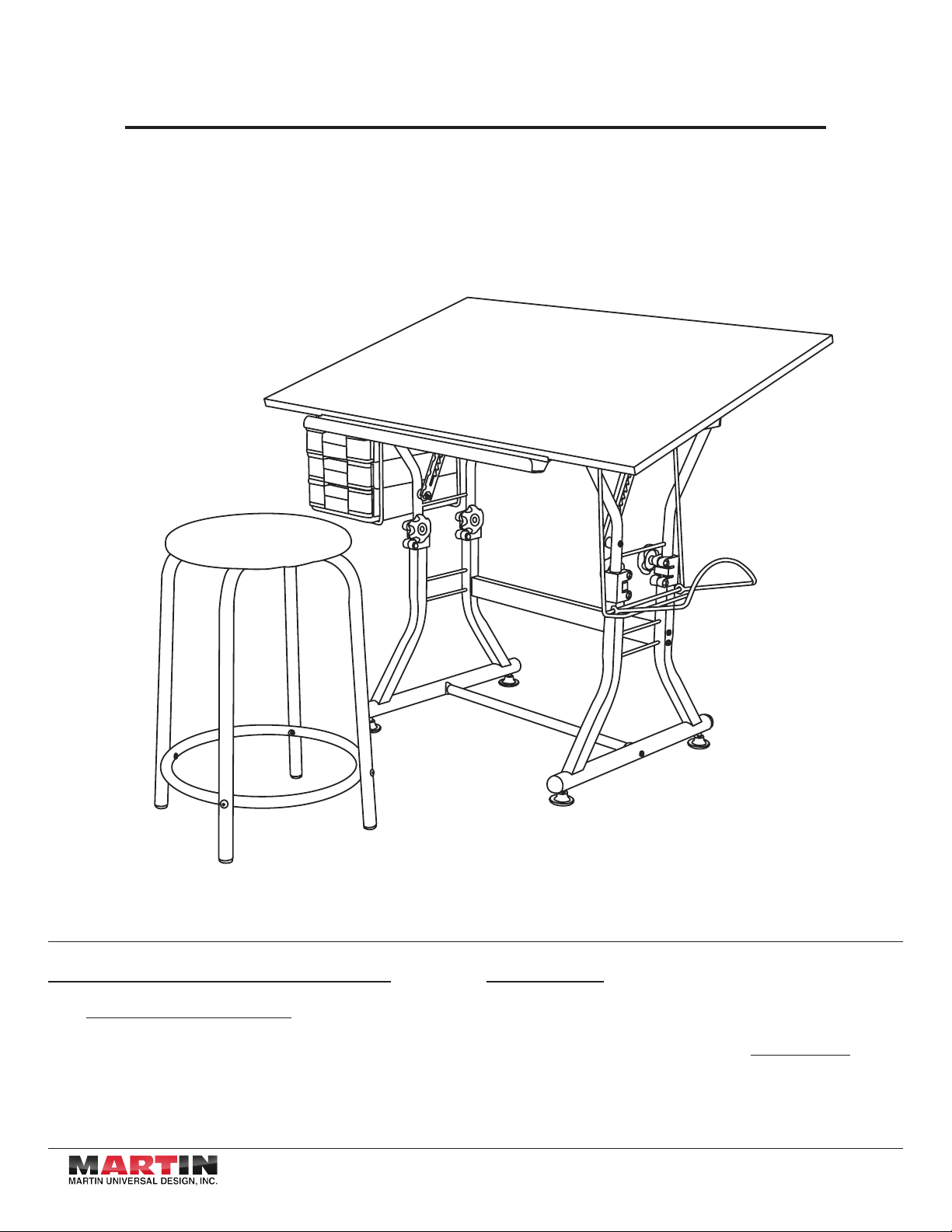
Ashley Table with Stool
Assembly Instructions
Video Assembly Instructions:
Go to www.MartinUniversalDesign.com and click on Assembly
Instructions to watch a video for HOW TO ASSEMBLE the
U-DS92ST Ashley Creative Center.
4444 Lawton Street, Detroit, MI 48208 USA / Tel: 1-313-895-0700 / Fax: 1-313-895-0709
E-mail: CustservMUD@gmail.com / www.MartinUniversalDesign.com
Model No. : U-DS92ST / U-DS92STB
Important:
If you have difficulty assembling your U-DS92ST Creative Center
or need customer service assistance, please call Martin Universal
Design, Inc. Customer Service Hot Line at 1-313-895-0700. If you
need additional parts, it is not necessary to contact your dealer,
our Customer Service Rep. will forward them to you immediately.
10/2011 - RPI
Page 2
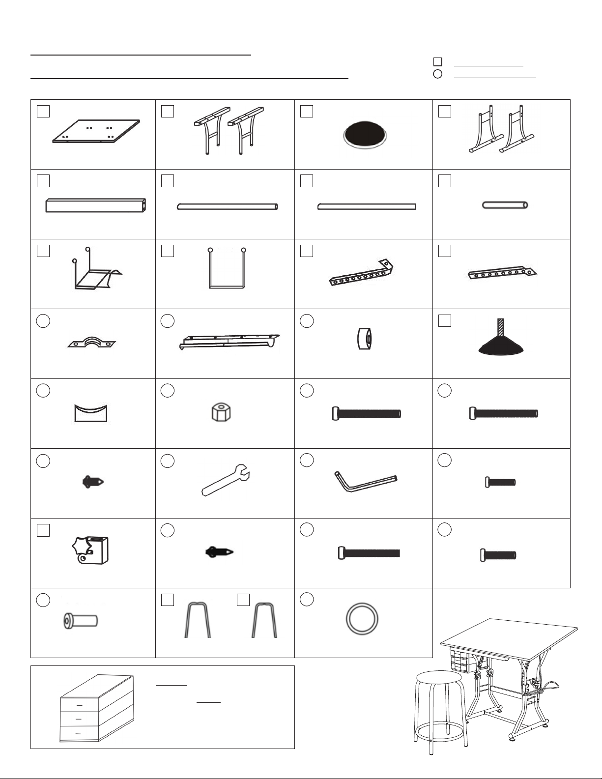
: Table Components
: Fasteners and Tools
25
U-DS92ST / U-DS92STB
Ashley Table with Stool Parts List
2
: TABLE COMPONENTS
: FASTENERS AND TOOLS
1
23.5” X 35.5” TOP
5
CROSS SUPPORT
9
MEDIA SUPPORT
13
BOARD BRACE CLAMP (2 EA.)
17
2
UPPER BASE LEFT & RIGHT END
6
BASE FLOOR SUPPORT
10
DRAWER SUPPORTS (2 EA.)
14
TOOL TROUGH
18
3
SEAT
7
BOARD BRACE
11
LEFT TILT MECHANISM
15
PLASTIC THICK WASHER (2 EA.)
19
4
LOWER BASE LEFT & RIGHT END
8
DRAWER SUPPORT RODS (2 EA.)
12
RIGHT TILT MECHANISM
16
FLOOR GUIDES (4 EA.)
20
FLOOR SUPPORT SPACER (2 EA.)
21
4 X 12MM SCREW (14 EA.)
25
COLLARS (4 EA.)
29
(4 EA.)
END CAP NUT (4 EA.)
22
WRENCH
26
4 X 14MM SCREW (8 EA.)
30
STOOL LEGS FOOTRING
Drawers
Please see page 8 assembly sheet
for drawers.
31
6 X 55MM BOLT (2 EA.)
23
ALLEN WRENCH (2 EA.)
27
6 X 40MM BOLT (4 EA.)
32
6 X 45MM BOLT (8 EA.)
24
6 X 25MM BOLT (6 EA.)
28
6 X 35MM BOLT (4 EA.)
10/2011 - RPI
Page 3
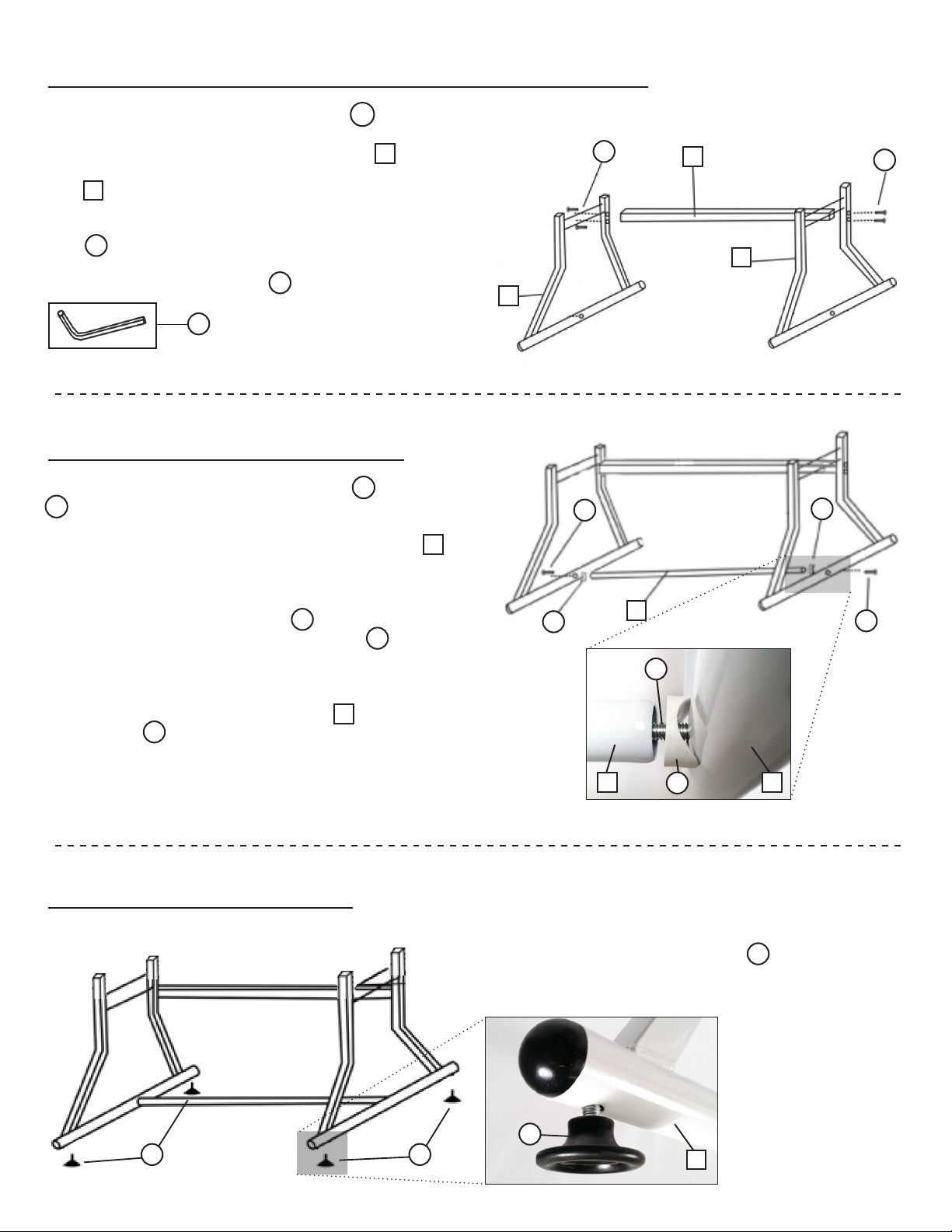
Step 1: Base Assembly & Cross Support
Fastener Parts Needed for this Step : 20 = 4 ea.
3
Start with taking the [2] Lower Base Ends (Part ),
spreading them apart, and inserting the Cross Support
(Part ) between them as seen in the Image.
5
Attach the three pieces together with [4] 6x45 mm bolts
20
(Part ).
Tighten with Allen Wrench (Part )
23
23
4
Step 2: Lower Base End
Fastener Parts Needed for this Step : 17 = 2 ea.
19 = 2 ea.
Now continue by taking the lower base end units (Part
and attach the base floor support, the long circular tube, to
the base ends.
4
20
4
19
5
4
17
20
Do this by putting a 6x55 bolt (Part ) through one of the
lower base ends. Then place the spacer (Part ) so it
rests against the lower base end making sure the C shape
faces the base end and the flat part faces you.
Now screw into Base Floor Support (Part ) using Allen
Wrench (Part ). Repeat for the opposite side!
23
19
17
6
Step 3: Floor Guides
17
Now attach the [4] Floor Guides (Part ) into the base by
screwing the guides into the specified holes on the bottom of
the base units.
6
19
6 4
17
16
19
16 16
16
4
10/2011 - RPI
Page 4

Step 4: Collars
Loosen the lower bolt below the knob on the collar. Line up
the square end with the base.
Slide/push on top of the base. It is beneficial to have the
knobs face inwards so they do not interfere with drawers or
Media supports.
Now tighten the lower bolt to make snug (being careful
not to over tighten)
Step 5: Upper Base Ends
4
25
2
Take each Upper Base End (Part ) so the holes face the
front of the desk.
Assemble by inserting the ends of the Upper Base Ends into
the [4] collars (Part ) on top of the base assembly.
Tighten knobs on collars to secure
(careful not to over tighten).
[For ease of further assembly allow upper base ends to go
all the way down until table is complete then adjust the table
to your desired height setting.]
25
2
Step 6: Drawer Supports
Fastener Parts Needed for this Step : 20 = 2 ea.
24 = 2 ea.
24
8
20
Attach Drawer Supports (Part ) to the left Upper Base
End (Part ).
- Insert 6x45mm bolt (Part ) on inside of the Upper Base End.
- Slide on Drawer Support (Part )
- Secure in place with Drawer Support Rod (Part ) using the
Allen Wrench (Part )
- Complete Drawer Support assembly by securing with 6x25mm
Bolt (Part )
Repeat process with second drawer support!
2
23
24
10
20
10
8
10
10/2011 - RPI
Page 5

Step 7: Media Support
Fastener Parts Needed for this Step : 27 = 2 ea.
18 = 2 ea.
- Attach Media Support (Part ) to upper portion base end
Insert 6x40mm bolts (Part ) through the 2 holes on the
right side of the upper base end.
- Place the media support (Part ) on the 6x40mm bolts
(Part )
27
[Make sure the media support is facing up like a fishing hook L]
- Secure with nut (Part )
- Secure with wrench (Part ) & Allen wrench (Part )
18
27
22
9
9
23
18
18
5
27
9
Step 8: Board Brace
Fastener Parts Needed for this Step : 21 = 10 ea.
Note: Lay the Table Top (Part ) onto a flat-carpeted
surface to avoid scratching the tabletop.
You will also need a Phillips head screwdriver.
*** Some of the holes are not pre drilled ***
Locate the set of pre drilled holes & place the Board Brace
(Part ) between the holes.
7
Make sure board brace has the holes facing parallel to the table
top so you can see through them and not into the tabletop.
1
27
1
13
9
21
7
13
21
13
21
Now place the Board Brace Clamps (Part ) over the Board Brace (Part ) on the
backside of the Table Top (Part ) and line up the Board Brace (Part ) with two of
1
13
7
7
the pre drilled holes.
You will have to screw in two of the holes into non-predrilled spots using self tapping
4x12mm screws screws (Part ).
21
All you have to do is keep turning and push down a little and the screws will tap and
thread themselves.
7
Tighten the 4x12mm screws (Part ).
21
Note: Secure these screws and then loosen a quarter turn. This allows for the tabletop
to move easily when making a tilt adjustment later on.
Repeat process with second board brace clamp.
10/2011 - RPI
Page 6

Step 9: Tool Trough
Fastener Parts Needed for this Step : 21 = 4 ea.
6
21
Attach Tool Trough (Part ) to the front ledge of the Table
Top (Part ).
Secure to ledge with [4] 4x12mm screws (Part ). They
are self-tapping screws
*** Some of the holes are not pre drilled ***
1
14
21
Step 10: Tilt Mechanism
Fastener Parts Needed for this Step : 26 = 8 ea.
With the Table Top (Part ) still on the floor, attach Tilt
Mechanisms (Parts & ) to the Table Top (Part ).
Line up tilt mechanisms with the pre drilled holes.
Make sure the stamp end of the tilt mechanism is on outside
closet to the edge of the table.
Secure the tilt mechanism to the tabletop with [4] 4x14mm
screws (Part )
26
111112
1
1
14
26
12
Repeat the process with the second Tilt mechanism
Step 11: Attach Top to Top Base
Fastener Parts Needed for this Step : 27 = 2 ea.
15 = 2 ea. 18 = 2 ea.
Turn the Table Top over and place it on the base. You will
need to kneel down to finish assembly
Insert a 6x40mm bolt (Part ) into the outer side of the base.
Now place the thick plastic washer (Part ) on the bolt
(Part ) thru the inside of the base.
27
Slide the tilt mechanism so the stamped side is next to the
plastic washer.
27
15
18
27
15
18
18
15
27
Secure with a nut (Part ) and tighten with the wrench
(Part ) and Allen Wrench (Part ) and tighten till snug.
22 23
DO NOT OVERTIGHTEN, otherwise the tilt mechanism will
not work smoothly.
18
27
15
10/2011 - RPI
Page 7

Step 12: Board Brace to Base
Fastener Parts Needed for this Step : 20 = 2 ea.
7
Attach Board Brace (Part ) to the base using the
6x45mm bolt (Part ).
Secure using the Allen Wrench (Part )
20
7
23
20
20
20
7
20
Step 13: Adjustments
HEIGHT ADJUSTMENT:
To adjust the height of your table - loosen the knobs on the collars found on the base of the
table and lift the table top to desired height.
TILT ADJUSTMENT:
To adjust the tilt of your table top, grab the back edge of the table top and lift the top with [2]
hands to the maximum tilt and then back down to your desired position.
NOTE: You must lift the table top all the way up before lowering it to the desired tilt level.
NOTE: If the top does not seem to move smoothly - this means you are NOT holding the top
balanced with both hands. Make sure your hands are positioned evenly. This will make the
adjustments easier.
LEVELING FLOOR GUIDES:
If your floor is uneven, you can adjust the floor guides by loosening the floor guides to make
up for the uneven floor.
In order to lower the table top, lift it all the way up to its maximum height which allows the tilt
mechanisms to release from their locked position. To avoid damaging the table top,
DO NOT attempt to lower the table top by forcefully pushing down on the top when its in a
locked position.
4444 Lawton Street, Detroit, MI 48208 USA / Tel: 1-313-895-0700 / Fax: 1-313-895-0709
E-mail: CustservMUD@gmail.com / www.MartinUniversalDesign.com
10/2011 - RPI
Page 8

Drawer Assembly Instructions
8
A
TOP - 1 PIECE INSIDE SECTION - 1 PIECE DRAWERS - 3 PIECESBOTTOM - 1 PIECE
WARNING: Read all instructions first before assembling drawers. Once pieces are snapped together they are secured.
Assemble your drawers by taking the section [A] and
snapping into place - by lining up the tabs with the grooves
in the outside edge of section piece [B].
Complete by snapping section [C] onto section A&B.
Finish by sliding the [3] Drawers into the
drawer bank assembly.
B
C
A
B
D
C
D
After proper assembly the drawers should
look like the above illustration.
IMPORTANT:
If you have difficulty assembling your U-DS92ST Creative Center or need customer service assistance. Please call: Martin Universal
Design, Inc. Customer Service Hot Line at 1-313-895-0700. If you need additional parts, it is not necessary to contact your dealer, our
Customer Service Rep. will forward them to you immediately.
4444 Lawton Street, Detroit, MI 48208 USA / Tel: 1-313-895-0700 / Fax: 1-313-895-0709
E-mail: CustservMUD@gmail.com / www.MartinUniversalDesign.com
10/2011 - RPI
Page 9

Stool Assembly Instructions
24 28 29
9
: TABLE COMPONENTS
: FASTENERS AND TOOLS
6 X 25MM BOLT
3 30 31 32
SEAT STOOL LEG
31
30
29
29
24
24
24
24
6 X 35MM BOLT
STOOL LEG FOOTRING
28
29
28
28
28
29
Begin by taking Part & , position
them as shown above. Insert part
between & .
Secure by inserting the [4] 6x25mm bolts
(Part ) through the inside back through
24
to the outside and thread into Part .
Tighten to secure.
31
32
303031
32
29
3
Attach Stool seat to stool assembly by
laying the seat onto the floor and place the
stool assembly over it.
Secure with [4] 6x35mm bolts (Part ).
Tighten down to secure.
28
Double check that all bolts are tightened.
Once that is complete Turn your stool
over onto its legs and use.
IMPORTANT:
If you have difficulty assembling your U-DS92ST Creative Center or need customer service assistance. Please call: Martin Universal
Design, Inc. Customer Service Hot Line at 1-313-895-0700. If you need additional parts, it is not necessary to contact your dealer, our
Customer Service Rep. will forward them to you immediately.
4444 Lawton Street, Detroit, MI 48208 USA / Tel: 1-313-895-0700 / Fax: 1-313-895-0709
E-mail: CustservMUD@gmail.com / www.MartinUniversalDesign.com
10/2011 - RPI
 Loading...