

Page 1
NEW U-DS90W/U-DS90B Creation Station Assembly Instr uctions
Additional Tool needed: Phiillips Screwdriver
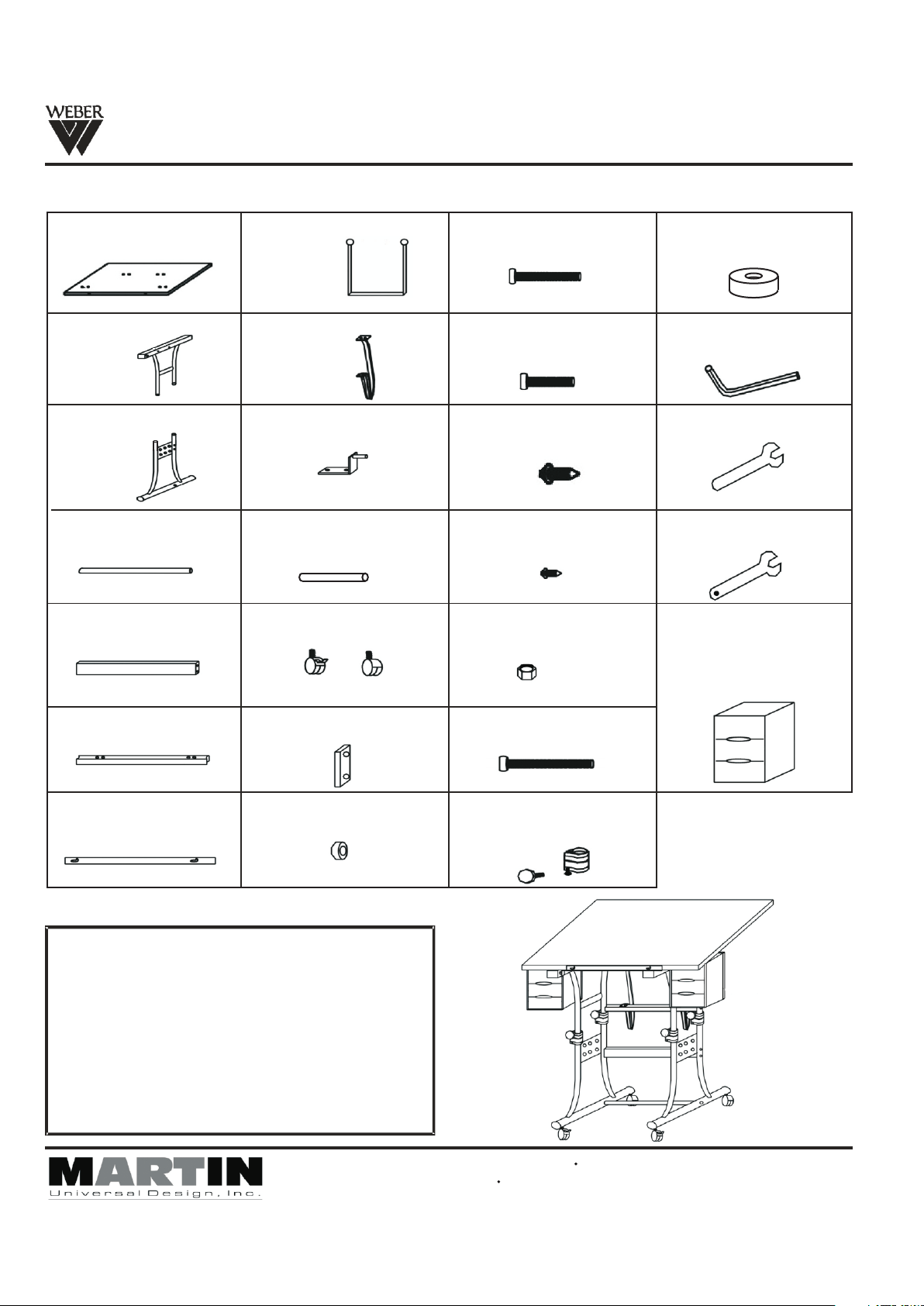
Parts List
[A] - 24" x 40" Top
(1 piece)
[B] - Upper Base End
(2 pieces)
[C] - Lower Base End
(2 pieces)
[D] - Foot Bar (1 piece)
[E] - Cross Support
(1 piece)
[H] - Drawer Supports
(4 pieces)
[I] - Tilt Mechanism
(2 pieces)
[J] - Top L-Brack et
(2 pieces)
[K] -
Drawer Supports
Rods
(4 pieces)
(2 Lockin g & 2 non-l oc king)
[L] - Castors
[O] - 6 x55mm
(6 pieces)
[P] - 6 x 28mm
(8 pieces)
[Q] - 5x14m m
(8 pieces)
[R] - 4 x 12mm
(2 pieces)
[S] - Nuts
(4 pieces)
[V] - Washer
(4 pieces)
[W] - All en Wrench
(1 pie ce)
[X] - Wrench (1 piece)
[Y] - Wrench with hole
(1 piece )
[Z] - Drawe rs
(2 sets - the se n eed
to be assem bl ed)
Please se e as sembly
sheet for d ra wers.
[F] - Top Support
(1 piece)
[G] - Pencil Ledge
(1 piece)
[M] - Cross S up port
End Cap (2 pi ec es)
[N] - Footbar Spacers
(2 pieces)
IMPO RTANT
If you have difficulty assembling your U-DS90W
Creation Station or need customer service
assistance. Please call:
Martin Universal Design, Inc.
Customer Service Hot Line at
1-313-895-0700.
If you need additional parts,
it is not necessary to contact your dealer,
our Customer Service Rep. will forward them
to you immediately.
4444 Lawton Avenue, Detroit, MI 48208 USA Tel:(313)895-0700/Fax:(313)895-0709
Emai l: C ustservmud@aol. com visit us at www.Mart in UniversalDesi gn .com
[T] - 6x65mm
(6 pieces)
[U] - Colla rs - i ncludes
knob and bolt
(4 pieces)
Pg. 1
Revis ed AUGUS T 09
Page 2
NEW U-DS90W/U-DS90B Creation Station
Assembly Instructions
O
T
FIG 1
N
(non- loc king cast or )
O
L
M
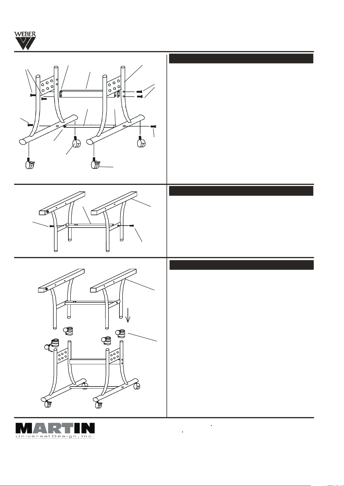
STEP 1] Assembly Base of Table
Begin by taking the [2] Lower Base End units (part C) and
attach the foot bar (part D) to the lower Base End units
using a foot bar spacer (part N) between each end of foot
O
bar and base end unit. Secure with [2] 6x65mm bolts (part
O). Loosley fasten bolts with Allen Wrench to allow for further
assembly of next step . See FIG 1.
Attach Cross support (part E) to each Base End Unit (part C).
First, attach the Cross Support End Caps (part M) to each
end of Cross Support. Continue by securing cross support to
leg of base unit with [2] 6x65mm bolts (part T). Tighten with
Allen Wrench and go back to tighten down foot bar
T
assembly bolts (part O) . See FIG 1.
Complete Step 1 by inserting [2] locking castors (part L)
into the front of the base end. Complete by inserting the [2]
remaining non-locking castors into the rear of the base.
Tig ht en d ow n wi th w re nc h (p ar t V) . Se e FI G 1.
D
C
E
N
L (lo cking cas tor)
STEP 2] Assembly Top portion of Base
F
B
Take each upper Base end (part B) attach to Top Surface
Cross Support (part F) using [2] 6x55mm bolts (part O).
Tig ht en a nd s ec ur e wi th Al le n Wrench. See FIG 2.
FIG 2
FIG 3
O
STEP 3] Complete Base Assembly
Before combining the top portion to the bottom portion, slide
the collars (part K) onto each of the [4] ends of the lower
portion of the base. Tighten lower bolt found below knob on
B
collar. This secures collar to leg. Repeat with all 4 collars.
See FIG 3.
Once the collars are on the base, insert the top portion into
the lower portion of the base making sure the top ends slide
into the collars that are on the lower portion of the base.
Secure with the [4] male knobs into the collars and tighten.
See FIG 3.
U
NOTE: Knobs on collars are to secure table at desired
heig ht.
NOTE: Knobs should face inside Part CLower Base End.
Pg. 2
4444 Lawton Avenue, Detroit, MI 48208 USA Tel:(313)895-0700/Fax:(313 )8 95 -0 70 9
Emai l: C ustservmud@aol. co m visit us at www.Martin Un iversalDesign.c om
Revis ed AUGUS T 09
Page 3

FIG 4
NEW U-DS90W/U-DS90B Creation Station
Assembl y Instr uctions
STEP 4] Attaching Tilt Mechanism
Take the [2] Ti lt M ec ha nisms (part I) and attach the one end
I
P
F
S
B
as show in F IG 4 t o th e Top Suppor t (p ar t F) u sing [2] 6x28mm
bolts (p ar t P) a nd [ 2] nuts (part S) per tilt mechanism. Tig ht en
with wre nc h (p ar t U) and Allen Wrench. Repeat w it h ot her
mechan is m. S ee F IG 4.
P
V
T
K
H
FIG 4B
STEP 4B] Attaching Drawer Supports
Attach d ra we r su pport(part H) to drawer support rod
(part K) using( part P) 6 x28mm bolt. Continue by
attach in g dr aw er support (part H) to upper
(part B) using (part T) 6x6 5 mm add (part V)between
upper ba se e nd a nd (p ar t H) drawer support.Repeat
assemb ly w it h th e remaining drawer supports.
SEE FIG 4B
After th e pr ev io us steps, the Assembled Base should no w
look lik e th e pi ct ure shown at left if proper assembly wa s
comple te d.
Contin ue w it h as sembly on next page.
base end
Pg. 3
Revis ed AUGUS T 09
Page 4

NEW U-DS90W/U-DS90B Creation Station Assembly Instructions
STEP 5] Attach Top to BaseFIG 5
NOTE: Us e [2 ] pe op le to help each other turn base over
onto Table Top.
Lay Table Top onto fl at c ar pe ted surface or empty flattened
carton i ns ur in g top wont scratch, making sure the T-nut holes
are faci ng u p.
I
Q
Now, plac e Ba se u pside down onto top by lining up holes in
Til t Mechanism (part I) with proper hole s in t op .
Note: The other [4] hole s in t op a re f or the L-Brackets .(part J)
Secure t op t o ba se u sing [2] each 5x14mm bolts (part Q) per
tilt mec ha ni sm ( part I). Secure with Allen Wrench. Repeat
with oth er Ti lt M ec hanism.
J
FIG 6
G
A
Q
Attach L -B ra ck ets (part J) by inserting rod found on L- Br ac ket
into bas e, c om pl ete by attaching L-bracket to top usi ng [ 2]
each 5x1 4m m bo lts (part Q) per L-bracket. Secure with Al le n
J
Wrench. Repeat with othe r side. See FIG 5.
STEP 6] Attachment of Pencil Edge
NOTE: Us e [2 ] pe op le to help each other turn base over
onto Cas to rs .
Attach P en ci l Ed ge (part G) to front edge of Top usi ng [ 2]
each 4x1 2m m sc re ws (part R). Tighten to secure. NOTE:
Keep screw slightly lo ose to allow for raising or low ering of
pencil e dg e. S EE F IG 6.
R
Revis ed AUGUS T 09
Pg. 4
FIG 7
STEP 7] Drawer Assembly
See Draw er Assembly Instruction shee t fo r as sembly.
H
Z
V
4444 Law to n Ave nue, Detroit, MI 48208 USA Tel:( 31 3) 895-0700/Fax:(313)895-070 9
Email: C us ts er vmud@aol.com visit us at www.Marti nU ni versalDesign.com
Assemb le D ra we rs (part Z) and then slide them into the
Drawer S up po rts (part H) found hanging on either si de o f
the tabl e. M ak e su re the drawer fronts are facing the fro nt
of the tab le . SE E FI G 7.
Once com pl et e, d ouble check all screws and bolts to mak e
sure the y ar e se cu re.
Table is now r ea dy f or your enjoyment!
Page 5

NEW U-DS90W/U-DS90B Creation Station
Drawer Assembly Instructions
Drawer Parts & Quantity (makes 2 Drawer Banks)
A B
Top - 2 Pieces Inside Section - 2 Pieces Drawers - 6 PiecesBottom - 2 Pieces
WARNING: READ ALL INSTRUCTIONS FIRST BEFORE ASSEMBLING DRAWERS.
ONCE PIECES ARE SNAPPED TOGETHER THEY ARE SECURED.
Assemble your drawers by
taking the section [A] and
snapping into place by lining up the tabs with the
grooves in the outside edge
of section piece [B].
Complete by snapping
section [C] onto section A&B.
A
B
C
D
Finish by sliding the
[3] Drawers into the
drawer bank assembly.
If you have diff ic ul ty a ss em bl ing your U-DS90W Drawers or need customer service assista nc e.
Please cal l: M ar ti n Un iv er sal Design, Inc. Customer Service Hot Line at 1-313-895-070 0.
If you need addi ti on al p ar ts , it i s no t necessary to contact your dealer,
our Customer S er vi ce R ep . wi ll forward them to you immediately.
C
After proper assembly
the drawers should look
like the above illustration.
D
IMPORTANT
4444 Lawto n Ave nu e, D et ro it, MI 48208 USA Tel:(313)895-0700/Fax:( 31 3) 89 5- 07 09
Email: Cus ts er vm ud @a ol .com visit us at www.MartinUniversalDesign.com
Part W
Revis ed AUGUS T 09
 Loading...