

Page 1
Ridgeline
Assembly Instructions
U-DS6000P
Since 1853
IMPORTANT
If you have difficulty assembling your U-DS6000P Ridgeline Table
or need customer service assistance. Please call:
Martin Universal Design, Inc. Customer Service Hot Line at 1-313-895-0700.
If you need additional parts, it is not necessary to contact your dealer,
our Customer Service Rep. will forward them to you immediately
Martin Universal Design, Inc. • Detroit, MI 48208 USA
Tel: 313-895-0700 • E-mail: custservMUD@aol.com
www.MartinUniversalDesign.com
.
November 09, RPI
Page 2
Since 1853
Ridgeline
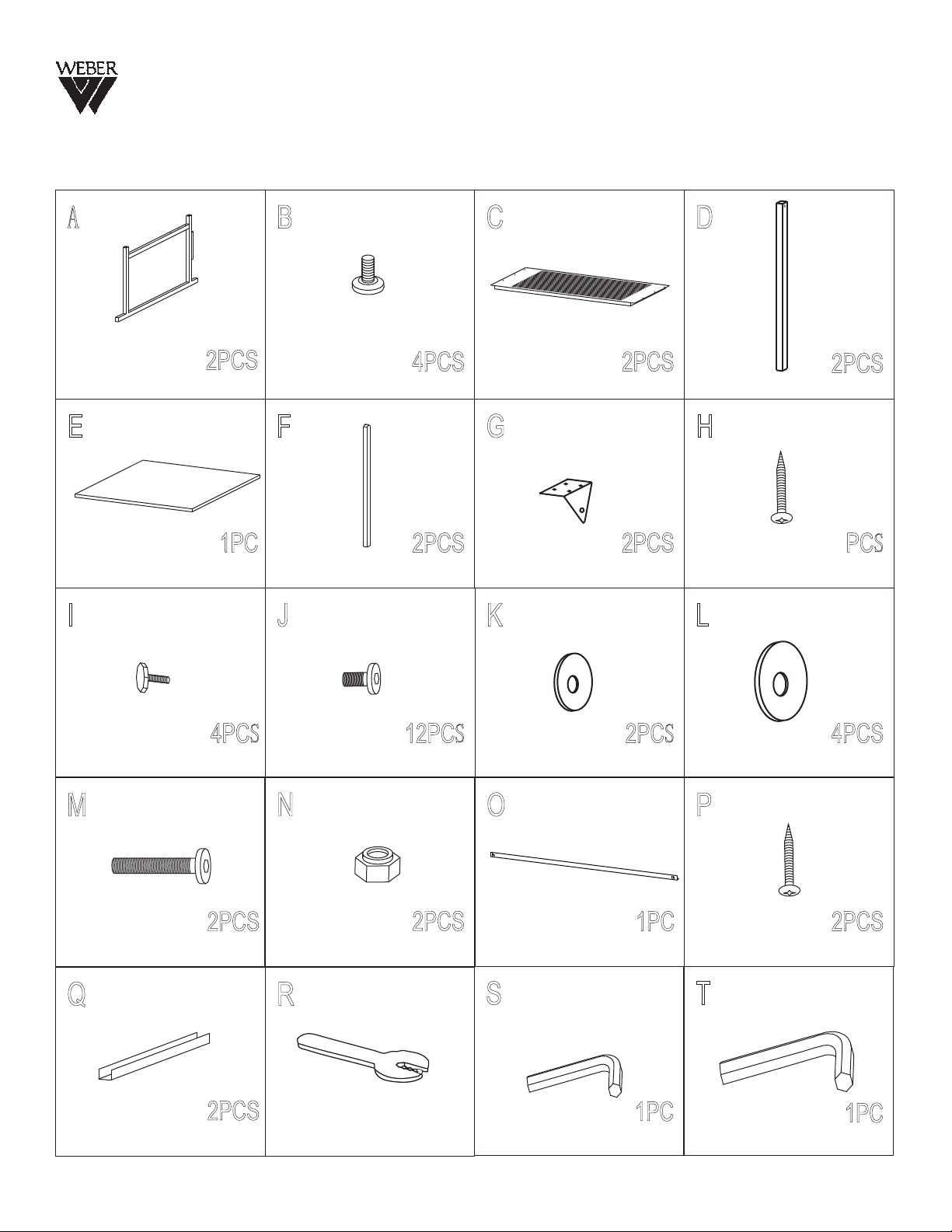
Hardware Parts List
A
E
I
B
2PCS
Side Support Floor Leveler Panel
4PCS
F
1PC
Top Tilt Mechanism
Height Adj. Tube
2PCS
J
C
2PCS
G
2PCS
K
D
Height Adj. Tube w/
H
14
4x14mm Screw
L
2PCS
hole
PCS
M
Q
4PCS
Knob
2PCS
8x50mm Bolt
2PCS
Metal Guide
N
R
12PCS
6x12mm Bolt
2PCS
Nut
1PC
Wrench
O
S
2PCS
Small Washer Large Washer
4PCS
P
1PC
Pencil Edge
4x12mm Screw
2PCS
T
1PC
#6 Hex Wrench
#8 Hex Wrench
November 09, RPI
1PC
Page 3

Since 1853
Ridgeline
Assembly
NOTE:
We reccommend the
The Assembly of this table to be
performed with two adult people.
STEP 1
Begin assembly of the Ridgeline table by taking
the side support (part A) and attaching the
oor levelers (part B) to the side supports.
See Fig 1
FIG 1
A
B
B
A
B
B
STEP 2
Continue by attaching the panel (part C)
to (part A) the side support, using 6 each
M6x12mm bolts (part J).
See Fig 2
STEP 3
Attach the second panel (part C) to (part A)
by using 6 each M6x12mm bolts (part J).
See Fig 3
FIG 2
FIG 3
C
C
Jx6
Jx6
Page 4

Since 1853
Ridgeline
Assembly
STEP 4
Attaching Height Adjustment Tubes.
To attach the height adjustment tubes
(part D + part F), use 4 each (part I) knob.
Leave a 12” gap from the top of the
side supports, and secure the tubes in place
by tightening the tubes with the knobs.
See Fig 4
STEP 5A
FIG 4
Fx2
FIG 5
Dx2
Ix4
HX8
GX2
Attach (part Q), metal guide, by using 6 each
4x14mm screws (part H).
See Fig 5
STEP 5B
Attach (part G), tilt mechanism, by using
8 each 4x14mm screws (part H).
See Fig 5
STEP 5C
Attach (part O) pencil edge to your desired
position using 2 each 4x12mm screws (part P).
There are no pre-drilled holes for pencil edge.
See Fig 5
HX6
O
QX2
PX2
E
PX2
E
Hx8
Page 5

Since 1853
Ridgeline
Assembly
STEP 6
Attach Base to Top
Attaching Tilt Mechanism to
Height Adjustment Tube.
To attach the tilt mechanism (part G) to the
height adjustment tube, you will need the
following parts 1 each (part M) 8x50mm bolt,
2 each (part L) washer, 1 each (part K) washer,
1 each (part N) nut. Follow the diagram in
Figure 6 to attach the parts in the correct
order. See Fig 6
FIG 6
N
G
K
L
L
D
M
 Loading...