

Page 1
U-DS40 SMART TABLE • Assembly Instructions
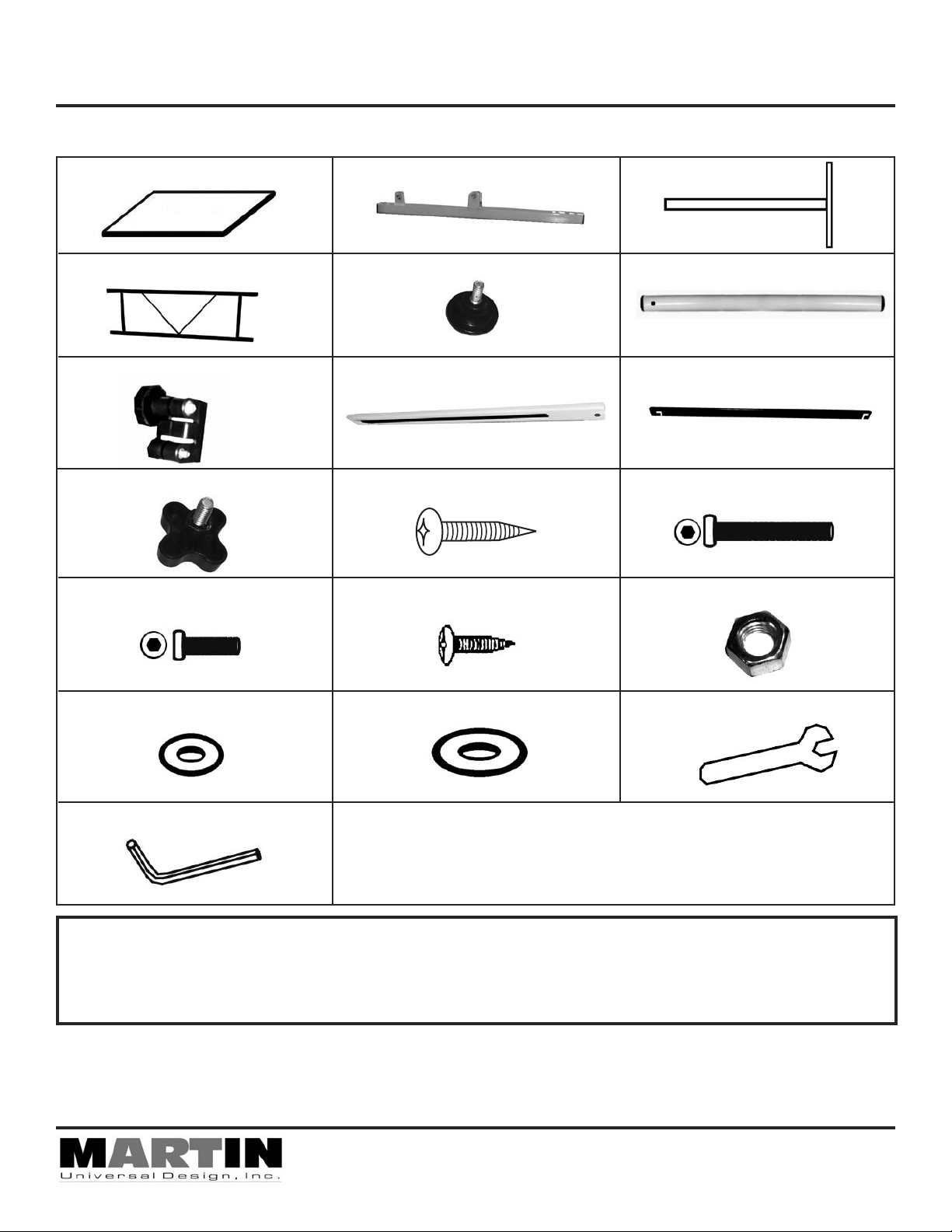
Parts List
[1 ea] - 24” x 36” Top
[1 ea] -Base Cross Support
[2 ea] - Collars
[2 ea] - Knobs
[2 ea] - Allen Bolts (6x12mm)
[2 ea] - Top & Base Supports
A
[4 ea] - Feet
D F
[2 ea] - Tilt Arms
G I
[8 ea] - Screws (6x25mm) [6 ea] - Allen Bolts (6x40mm)
B
E
H
[2 ea] - Legs
[2 ea] - Upper Legs
[1 ea] - Pencil Edge
J LK
[2 ea] - Screws [4 ea] - Nuts
C
M ON
[4 ea] - Small Washer
[2 ea] - Large Washer [1 ea] - Wrench
P1 QP2
[1 ea] - Allen Wrench
R
IMPORTANT
If you have difficulty assembling your U-DS40 Smart Table or need customer service assistance.
Please call: Martin Universal Design, Inc. Customer Service Hot Line at 1-313-895-0700.
If you need additional parts, it is not necessary to contact your dealer, our Customer Service Rep.
will forward them to you immediately.
NOTE: READ ALL ASSEMBLY INSTRUCTIONS FIRST
BEFORE ATTEMPTING TO ASSEMBLE U-DS40 SMART TABLE.
- TWO PEOPLE NEEDED FOR TABLE ASSEMBLY -
4444 Lawton Avenue, Detroit, MI 48208 USA • Tel:(313)895-0700/Fax:(313)895-0709
Email: Custservmud@aol.com • visit us at www.MartinUniversalDesign.com
Pg. 1
03/2009- RPI
Page 2
U-DS40 SMART TABLE • Assembly Instructions
FIG 1
B
K
K
FIG 1b
A
K
K
Make sure the base
supports are
positioned so that the
tab is on the outer
side of the base
support.
See image to the left
FIG 1b.
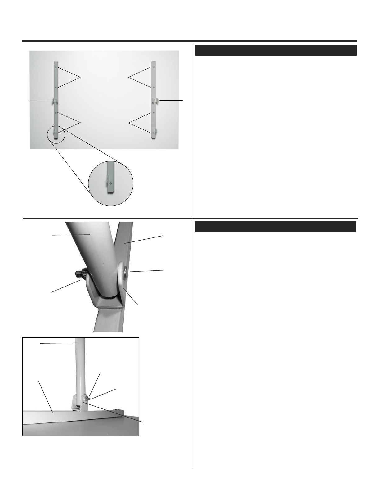
STEP 1] Attach Base supports to Top
IMPORTANT:
ASSEMBLE TABLE ON FLAT CARPETED
SURFACE TO PROTECT TOP FROM MARRING
Begin by taking your table top (part A) and lay it face
B
down onto your flat carpeted work surface
(holes facing up). Take [2 each] Base Supports
(part B) and position them so that they line up with the
holes in the top and metal tab is positioned on the outer
side of the base support.
See FIG 1b.
Using [4 each] 6x25mm Screws (part K) per base
support. Secure by tightening these screws to secure
base support to top. Repeat with second base support
(part B).
FIG 2
F
B
F
O
O
FIG 2b
L
B
L
welded brace
STEP 2] Attach Upper Legs
To attach the upper legs (part F) to the base supports
(part B), line up the hole found in the upper leg with the
welded brace found on the base support. Line up the
holes, insert a 6x40mm Allen Bolt through the welded
brace then through the upper leg and then through
the other side of the welded brace add a nut (part O).
Tighten to secure.
See FIG 2 & 2b.
Repeat with second upper leg.
welded brace
Pg. 2
03/2009- RPI
Page 3

U-DS40 SMART TABLE • Assembly Instructions
L
C
E
C
E
D
FIG 3
C
C
STEP 3] Attach Adjustable Rubber Feet
Attach the [4] adjustable rubber feet (part E) to Legs
(part C) by threading the rubber feet clockwise into the
bottom holes of the legs. See Fig 3 images.
NOTE: To adjust the level of the base once assembled,
unscrew or tighten each rubber foot until table is level.
STEP 4] Base Assembly
Take the [2] legs (part C) that have the rubber feet
attached and the [1] Base cross support (part D).
Attach the base support (part D) to each leg using [2
each] 6x40mm Allen bolts (part L) to each leg. Line up
holes in the legs to the ends of the base support. Insert
bolt through outer side of legs and into holes on end
L
of base Support.
Tighten bolts with Allen Wrench.
See FIG 4
FIG 5
FIG 4
Zoom of Bolt attachment
G
C
STEP 5] Attach Collars to Base Legs
Attach the [2 each] Collars (part G) to the top ends of
the legs as shown in the picture in FIG 5.
Make sure the knob is positioned on the outer side
of the legs.
NOTE: Loosen the knob on the collar (part G) prior
to sliding the collar down over the legs (part C).
Pg. 3
03/2009- RPI
Page 4

U-DS40 SMART TABLE • Assembly Instructions
STEP 5] Attach Top to Base
G
TOP - A
F
G
FIG 6
STEP 5] Attach Top to Base
IMPORTANT: USE TWO PEOPLE FOR THIS STEP
Loosen knobs on collars (part G) to allow the upper
legs to be inserted into the collars easier.
Have each person hold onto the table top and guide
the [2] upper legs (part F) into the collars that are attached to the base assembly. Tighten knobs on collars
to secure.
SEE FIG 6.
C
M
P1
P2
P1
O
B
H
H
FIG 7
J
STEP 7] Attach [2] Tilt Arms to Table
You need the [2] Knobs (part J), [2] Tilt Arms (part H),
and [2] Large Washers (part P2) to attach Tilt Arms to
table.
Insert the bolt that is connected to the Knobs (part J)
through the tilt arm (use the end that is opposite the
hole) add the large washer (part P2) to the knob bolt
and then thread into the table legs.
Repeat with opposite side. SEE FIG 7.
NOTE: These are the Knobs that you will loosen to
adjust the tilt of the table.
STEP 8] Attach [2] Tilt Arms to Top
To attach the Tilt Arm (part H) to the Top Support (part
B), you will need to insert the 6x12mm allen bolt (part
M) with a small washer (part P1) through the tilt arm,
then through the top support tab. Continue by adding
another washer (part P1) to the end of the bolt and finish
by adding a nut (part O). Tighten with wrench (part Q)
to secure. Repeat with other Tilt Support.
SEE FIG 8.
Pg. 4
H
F
03/2009- RPI
Page 5

FIG 9
U-DS40 SMART TABLE • Assembly Instructions
STEP 9] Attach Pencil Ledge
Attach Pencil Ledge (part I) to the front edge of the Top
using [2] Screws (part N). Tighten to secure.
NOTE: Slightly loosen screw to allow for raising or
lowering of pencil ledge.
SEE FIG 9 & FIG 9B
FIG 9B - ZOOM of Pencil Ledge attachment
Once complete, double check all screws and bolts to
STEP 10] Tighten All Screws and Bolts
make sure they are secure.
Enjoy Your New SMART TABLE!
HEIGHT ADJUSTMENT:
To adjust the height of your table - loosen the knobs on the collars found on the base of the table and lift the table top to
desired height.
TILT ADJUSTMENT:
To adjust the tilt of your table top, loosen the knobs on the side of the legs and hold onto table top and tilt to desired angle.
Tighten knobs on legs to secure.
LEVELING FLOOR GUIDES:
If your floor is uneven, you can adjust the floor guides by loosening the floor guides
to make up for the uneven floor.
4444 Lawton Avenue, Detroit, MI 48208 USA • Tel:(313)895-0700/Fax:(313)895-0709
Email: Custservmud@aol.com • visit us at www.MartinUniversalDesign.com
Pg. 5
03/2009- RPI
 Loading...