

Page 1
Assembly Instructions
U-DS1776R
Since 1853
IMPORTANT
If you have difficulty assembling your U-DS1776R Liberty Table
or need customer service assistance. Please call:
Martin Universal Design, Inc. Customer Service Hot Line at 1-313-895-0700.
If you need additional parts, it is not necessary to contact your dealer,
our Customer Service Rep. will forward them to you immediately
Martin Universal Design, Inc. • Detroit, MI 48208 USA
Tel: 131-895-0700 • E-mail: custservMUD@aol.com
www.MartinUniversalDesign.com
.
August 08, RPI
Page 2
Since 1853
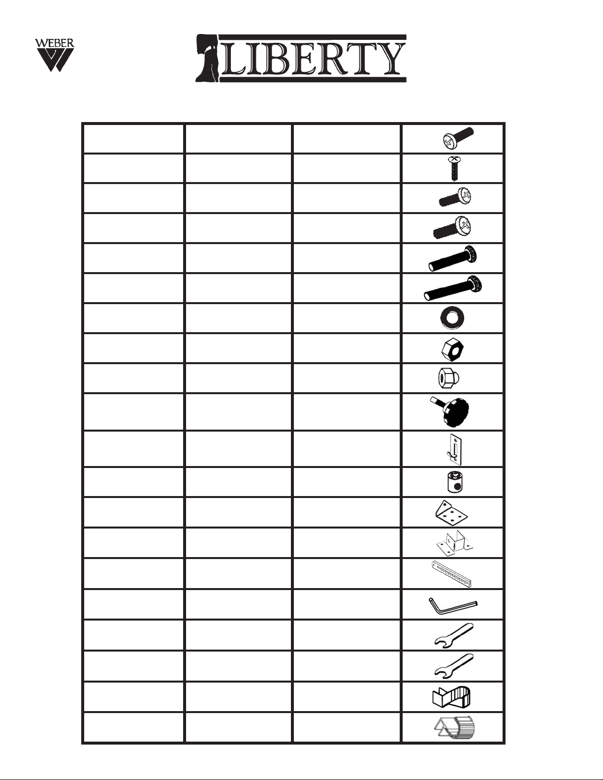
Hardware Parts List
A M5 x 1202 ea.
B M4 x 1412 ea.
C M6 x 1202 ea.
D M6 x 1902 ea.
E M6 x 3506 ea.
F M6 x 4008 ea.
G 20 x 2.002 ea.
H M606 ea.
I M802 ea.
J M16 x 5302 ea.
K
01 ea.
L 08 ea.
M 01 ea.
N 02 ea.
O 01 ea.
P M401 ea.
Q M1001 ea.
60 x 25 x 20
R M1401 ea.
S 01 ea.
T 01 ea.
August 08, RPI
Page 3
Since 1853
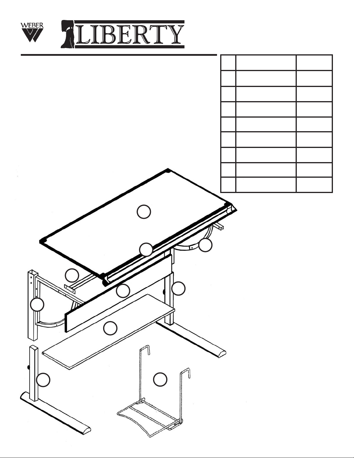
Parts List
1 Base Foot 2 ea.
2 Side Support 1 ea.
3 Side Support 1 ea.
4 Top Support 1 ea.
5 Mod. Panel 1 ea.
6 Shelf 1 ea.
7 Top 1 ea.
8 Side Shelf 1 ea.
9 Pencil Trough 1 ea.
3
4
6
5
7
2
9
1
1
8
August 08, RPI
Page 4

Since 1853
Assembly
NOTE:
We reccommend the
The Assembly of this table to be
performed with two adult people.
STEP 1
Begin assembly of Liberty table by taking
each base (part 1) and slide parts 2 & 3 over
the upright column of part 1. Secure with
one knob by tightening clockwise to each
assembled base leg (part J). See Fig 1
STEP 2
FIG 1
Part 3
Part 2
Zoom of
Knob
attachment
J
FIG 2
Continue by attaching the top support
(part 4) to the [2] base leg assemblies. Have
one person hold one end of Part 4 while the
other
legs.
Using 2 ea. part E bolts, insert these into the
2 holes found on the top edge of parts 2 &3
and into the 2 holes on the ends of part 4.
Secure and tighten with 2 ea. Nuts (part H).
See FIG 2.
Repeat with other side
person attaches Part 4 part to the base
E
4
Zoom of Part 4
attachment
H
4
August 08, RPI
Page 5

Since 1853
Assembly
STEP 3
This step involves attaching the Modesty
Panel (part 5) to the table base.
To do so you must use 2 ea. Cam Locks
(part L). Insert the cam locks in the rear
side of the Modesty Panel by placing them
into the pre-drilled holes that can be found
near each of the 4 corners. Make sure the
Phillips screwdriver head is facing out of the
modestly panel holes.
Continue by lining up the holes in the ends
of the Modesty Panel with the holes in the
side of the base legs. Secure to base using
2 ea. bolts (part F). Tighten down bolts, while
holding Cam Locks (part L) with screwdriver
so they do not move. See FIG 3.
Repeat with other end of Modesty Panel to
complete assembly of Step 3.
F
Zoom of
Modesty Panel
attachment
5
5
FIG 3
L
STEP 4
Attaching Shelf (part 6) to base.
o do so you must use 2 ea. Cam Locks
T
(part L). Insert the cam locks into the holes
found on the bottom of the shelf. You will
need to hold these in place with your finger.
Continue, by lining up the holes in the edge
of the shelf with the holes in the base legs.
Secure to base using 2 ea. bolts (part F).
Tighten down bolts, while holding Cam
Locks (part L) with screwdriver so they do
not move. See FIG 3.
Repeat with other end of Shelf to complete
assembly of Step 4.
Zoom of
Shelf attachment
6
L
FIG 4
F
F
August 08, RPI
Page 6

Since 1853
Assembly
STEP 5
Attachment of Table Top Tilt Mechanism
NOTE: Make sure Tilt Mechanism is on
correct position as show in FIG 5.
Begin by taking the Table Top Tilt
Mechanism (Part O) and attaching it to the
welded block with hole found at the center
of the Top Support. Secure by inserting
one bolt (part D) through the hole of the Tilt
Mechanism (as shown in Zoom of FIG 5)
then add [1] washer (part G), continue going
through the welded block and securing with
a Capped Nut (part I). Tighten Capped Nut
to bolt. See FIG 5.
STEP 6
Attachment of Table & Tool Trough Corners
Turn Table Top so that its bottom
Is face up.
S
Position of Tilt
O
Mechanism (part 4)
& Zoom of Tilt
Mechanism attachment
I
D
G
FIG 5
FIG 6
T
Take the [2] Tool Trough Corner protectors
(parts S & T) and slide them onto each end
of the tool trough and two corners of the
table top. See FIG 6. Secure with [1] screw
(part C) to each corner protector. See FIG 7
STEP 7
Attaching Base & Top Brackets
Attach the [2] Base brackets (part N) to the
underside of the top in specified pre-drilled
holes using 4 ea. screws (part B) in each
clamp. Tighten to secure. Repeat with other
side.
Attach Tilt Mechanism Bracket to underside
of the top in specified pre-drilled holes
using 4 ea. screws (part B). Tighten to
secure. Please refer to FIG 7 for proper
positioning of brackets.
B
C
N
M
B
7
B
Zoom of
attachment
FIG 7
August 08, RPI
Page 7

Since 1853
Assembly
STEP 8
Attaching Base to Top
To attach the Base to the top, you will need
to position the end of the top rail of each
base leg into the Base Bracket (part N) as
indicated in the Zoom portion of FIG 8.
After positioning it properly secure it in place
using 1 ea. Bolt (part E) and 1 ea. Nut
(part H). Tighten down to secure. Repeat
with second bracket on other end of table.
FIG 8
Zoom of
attachment
H
E
N
STEP 9
Attaching Tilt Mechanism to Top Bracket
To attach the Tilt Mechanism (part O) to the
top bracket, you will need to position the
end of the tilt mechanism into place on the
bracket.
it in place by inserting 1 ea. Bolt
(part D) through the mechanism then place a
washer (part G) over the bolt end, continue
going through the bracket (part M) and
complete with 1 ea. Capped Nut (part I).
ighten to secure.
T
See FIG 8 for a detailed image.
After positioning it properly secure
FIG 9
Zoom of
attachment
I
O G
M
D
August 08, RPI
Page 8

Since 1853
Assembly
STEP 9
Attaching Accessory Hook
To attach the Accessory Hook, position the
hook plate (part K) over the 2 holes found in
the side of the table base.
Secure using 2 ea. bolts (part A). Tighten.
See FIG 9 for detailed image.
This Accessory Hook can be used for
keys, hang bag, sealable pot holder and
brush washer.
FIG 9
A
K
STEP 10
Placement of Folding Side Utility Shelf
The Folding Side Utility Shelf can be placed
on either the Left or Right Side of the table.
Once your choice has been decided hook
the top of the shelf (the “upside down “J”
portion over the top edge of either side as
indicated in FIG 10.
Before you use your table, double check ALL
Bolts and screws to make sure all is secure.
One done your NEW LIBERTY Table is
ready to use. ENJOY!
Martin Universal Design, Inc. • Detroit, MI 48208 USA
Tel: 131-895-0700 • E-mail: custservMUD@aol.com • www.MartinUniversalDesign.com
Since 1853
FIG 10
August 08, RPI
 Loading...