

Page 1
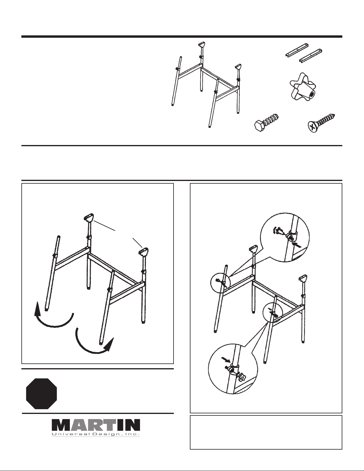
BERKELEY U-DS1400C ASSEMBLY INSTRUCTION
B. Metal Guides
ITEM# PARTS LIST QTY
97-DS140A A. Stand Frame 1
97-DS140B B. Metal Guide 2
97-DS140C C. Plastic Knob 4
97-DS140D D. Hex Bolt 4
97-DS140E E. Phillips Screw 14
84-2100C 30 x 42 White Top 1
C. Plastic Knob
D. Hex Bolt
A. Stand Frame
Your new U-DS1400C Berkeley Table has been designed and manufactured to enhance your productivity and efficiency.
This sturdy folding table, properly assembled, will last through years of use. Follow the instructions below to assemble your
table and refer to the enclosed parts list for part identification. Tools needed for assembly: phillips screwdriver, hammer, nail
or awl, tape measure and pencil. Begin by unpacking the carton and making sure you have all parts listed.
1. Swing the left and right side legs out
as shown. See Fig. 1
2. Put the hex bolt [D] inside the clamp
(See Fig. 2) and then attach knob [C]
E. Phillips Screw
and tighten. (See Fig. 3)
Brackets
Fig. 2
Fig. 1
Any Questions with Assembly? We Can Help
PLEASE DO NOT RETURN THIS TABLE to the
Store where you purchased it. If you are unable
STOP
Martin Universal Design, Inc. • 4444 Lawton Avenue, Detroit, MI 48208 USA
Tel: (313)895-0700 / Fax:(313)895-0709 • E-mail: Custservmud@aol.com
to assemble or parts are missing, PLEASE Call
Customer Service at
Martin Universal Design, Inc.
313-895-0700 or Email: custservmud@aol.com
NOTE:
Make sure the collar
is in the correct posi-
Fig. 3
tion as shown.
See Fig. 3
This Martin Universal Design, Inc. product has a one year guarantee
to be free from manufacturers defects during that period of use by the
original purchaser. Items or parts subjected to extreme temperature or
abuse or use of this product other than manufacturers intended purpose
is not covered under this guarantee.
ONE YEAR GUARANTEE
Created 06/06 RPI
Page 2
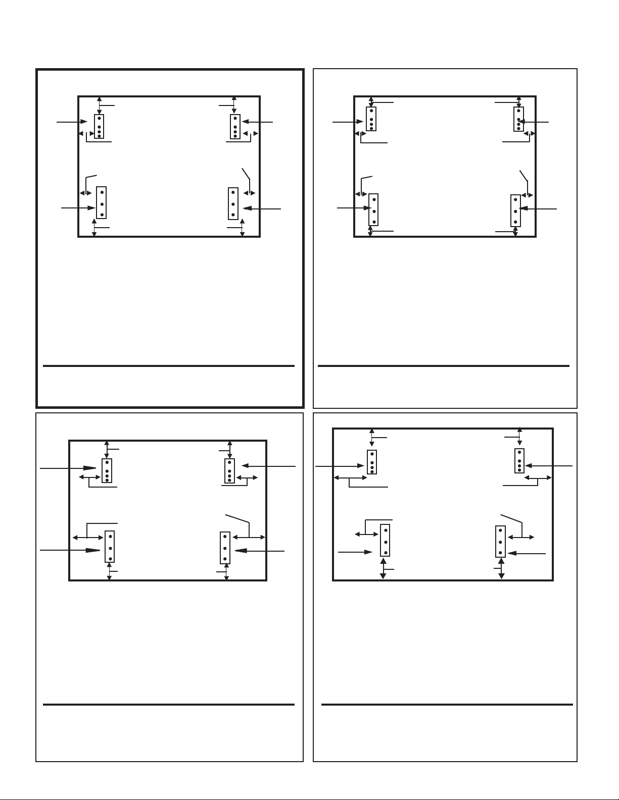
BERKELEY U-DS1400C TOP ASSEMBLY INSTRUCTION
If you purchase optional Tops B, D or P use the appropriate instruction for the top assembly.
Instructions for 30” x 42” C Top
This is the top included in the U-DS1400C Package
Step [3] 3” from back edge
Step [3]
5-5/8” from
left edge
Step [2] 6” from left side to
left edge of Metal Guide
Step [3]
5-5/8” from
right edge
Step [2] 6” from right side to
right edge of Metal Guide
Metal
Guide
Step [2] 2” from front edge
Step 1. Place top onto carpeted floor. Laying best surface face down.
Step 2. Attach Left and Right Metal Guides [B] by: Measuring 6” in
from left edge and mark with pencil, repeat with right side.
See above illustration. Measure 2” from front edge and make
pencil mark. Repeat with other side for Metal Guides. Mark
holes and then break surface with nail or awl. Secure with [3]
Phillip screws [E] per metal guide [B].
Step 3. Attaching Left and Right Brackets (already attached to base)
by: Measuring 5-5/8” in from left edge and mark with pencil,
repeat with right side. See above illustration. Measure 3” from
rear edge and make pencil mark. Repeat with other side for
Brackets. Break surface with nail or awl. Repeat with right side.
Secure with [4] Phillip Screws.
BracketBracket
Metal
Guide
Instructions for 24” x 36” B Top
Step [3] 1.25” from back edge
Step [3]
Step [3]
2-5/8” from left
edge
Step [2] 3” from left side to
left edge of Metal Guide
2-5/8” from
right edge
Step [2] 3” from right side to
right edge of Metal Guide
Metal
Guide
Step [2] 1.25” from front edge
Step 1. Place top onto carpeted floor. Laying best surface face down.
Step 2. Attach Left and Right Metal Guides [B] by: Measuring 3” in
from left edge and mark with pencil, repeat with right side.
See above illustration. Measure 1.25” from front edge and
make pencil mark. Repeat with other side for Metal Guides.
Mark holes and then break surface with nail or awl. Secure
with [3] Phillip screws [E] per metal guide [B].
Step 3. Attaching Left and Right Brackets (already attached to base)
by: Measuring 2-5/8” in from left edge and mark with pencil,
repeat with right side. See above illustration. Measure 1.25”
from rear edge and make pencil mark. Repeat with other side
for Brackets. Break surface with nail or awl. Repeat with right
side. Secure with [4] Phillip Screws.
BracketBracket
Metal
Guide
Please Note:
Reason for breaking top surface by tapping a nail or awl in screw
holes, is to make starting hole in surface to allow for easier attachment of screws.
Instructions for 31.5” x 48” D Top
Step [3] 3.75” from back edge
Bracket
Step [3]
8-5/8” from left
edge
Step [2] 9” from right side to
Step [2] 9” from left side to
Metal
Guide
Step 1. Place top onto carpeted floor. Laying best surface face down.
Step 2. Attach Left and Right Metal Guides [B] by: Measuring 9” in
from left edge and mark with pencil, repeat with right side.
See above illustration. Measure 2.75” from front edge and
make pencil mark. Repeat with other side for Metal Guides.
Mark holes and then break surface with nail or awl. Secure
with [3] Phillip screws [E] per metal guide [B].
Step 3. Attaching Left and Right Brackets (already attached to base)
by: Measuring 9” in from left edge and mark with pencil,
repeat with right side. See above illustration. Measure 3.75”
from rear edge and make pencil mark. Repeat with other side
for Brackets. Break surface with nail or awl. Repeat with right
side. Secure with [4] Phillip Screws.
left edge of
Metal Guide
Step [2] 2.75” from front edge
Step [3]
8-5/8” from
right edge
right edge of Metal Guide
Bracket
Metal
Guide
Please Note:
Reason for breaking top surface by tapping a nail or awl in screw
holes, is to make starting hole in surface to allow for easier attachment of screws.
Instructions for 36” x 48” P Top
Step [5] 5.5” from back edge
Step [3]
8-5/8” from
left edge
Step [2] 9” from right side to
right edge of Metal Guide
Step [2] 9” from left side to
left edge of
Metal Guide
Metal
Guide
Step 1. Place top onto carpeted floor. Laying best surface face down.
Step 2. Attach Left and Right Metal Guides [B] by: Measuring 9” in
from left edge and mark with pencil, repeat with right side.
See above illustration. Measure 5.5” from front edge and
make pencil mark. Repeat with other side for Metal Guides.
Mark holes and then break surface with nail or awl. Secure
with [3] Phillip screws [E] per metal guide [B].
Step 3. Attaching Left and Right Brackets (already attached to base)
by: Measuring 9” in from left edge and mark with pencil,
repeat with right side. See above illustration. Measure 5.5”
from rear edge and make pencil mark. Repeat with other side
for Brackets. Break surface with nail or awl. Repeat with right
side. Secure with [4] Phillip Screws.
Step [4] 5.5” from front edge
Step [3]
8-5/8” from
right edge
Metal
Guide
BracketBracket
Please Note:
Reason for breaking top surface by tapping a nail or awl in screw
holes, is to make starting hole in surface to allow for easier attachment of screws.
Please Note:
Reason for breaking top surface by tapping a nail or awl in screw
holes, is to make starting hole in surface to allow for easier attachment of screws.
Created 06/06 RPI
 Loading...