

Page 1
U-9601
ASSEMBLY INSTRUCTIONS
Martin/F. Weber Co. • 4444 Lawton Avenue, Detroit, MI 48208 USA
Tel:(313)895-0700 • Fax:(313)895-0709 • E-mail:Custservmud@aol.com
www.MartinUniversalDesign.com • www.weberart.com
Made in China
Rev June 08 RPI
Page 2
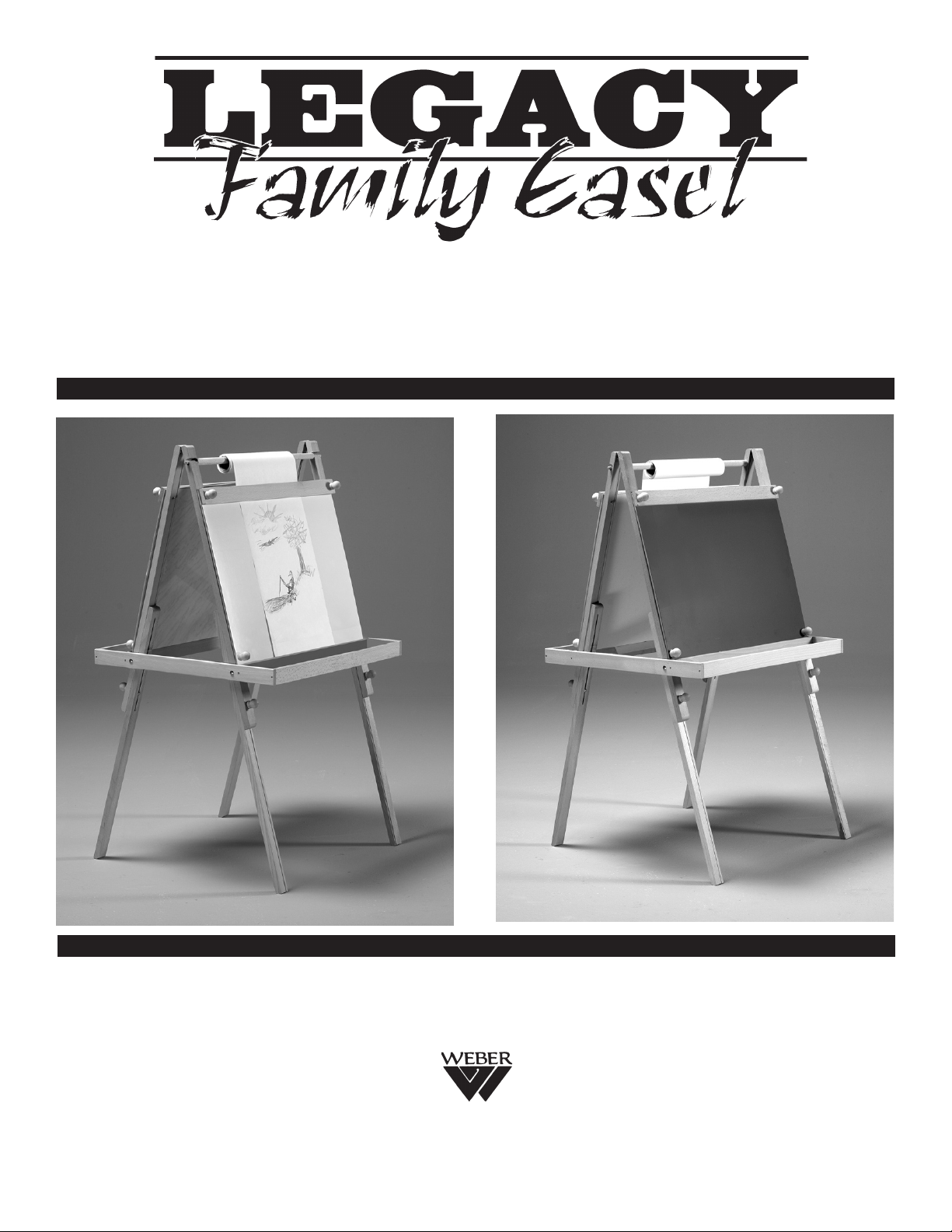
U-9601 • LEGACY FAMILY EASEL
ASSEMBLY INSTRUCTIONS
NO TOOLS NEEDED
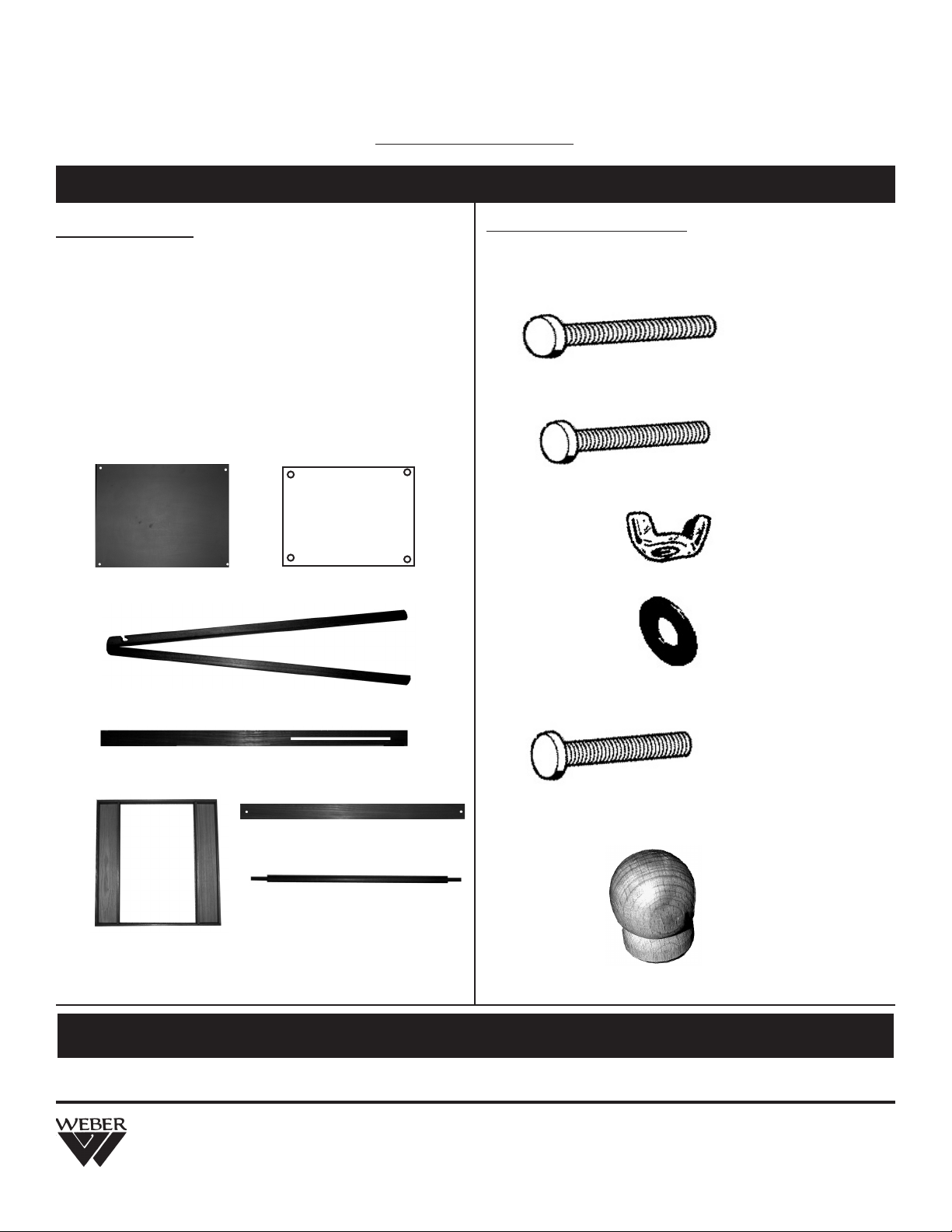
MAKE SURE CARTON CONTAINS THE FOLLOWING PARTS
WOOD PARTS
Quantity ....... Description ID#
1 ea. ........ Chalkboard Surface [A]
1 ea. ........ White Drawing Surface [B]
2 ea. ........ Upper Legs with Hinges [C]
2 ea. ........ Lower Legs with Channel [D]
1 ea. ........ Materials Tray [E]
1 ea. ....... Cross Supports [F]
1 ea. ........ Paper Roll Holder [G]
Chalkboard Surface [A] White Drawing Surface [B]
HARDWARE PARTS
Quantity ........ Description ID#
4 ea. ............. 2-3/8” Bolts [H]
[H]
4 ea. ............. 2” Bolts [I]
[ I ]
8 ea. .............. Wing Nuts [J]
[J]
8 ea. .............. Washers [K]
[K]
Upper Legs with Hinges [C]
Lower Legs with channel [D]
Cross Supports [F]
Paper Roll Holder [G]
Materials Tray [E]
8 ea. ............1-5/8” Bolts (attached to wooden knobs) [L]
8 ea. ............Wooden Knobs (attached to 1-5/8” Bolts) [M]
For recommended assembly lay all wood parts on flat carpeted surface.
If you have any problems with assembling this easel, please call: (313)895-0700
or e-mail us at Custservmud@aol.com. Thank You.
Martin/F. Weber Co. • 4444 Lawton Avenue, Detroit, MI 48208 USA
Tel:(313)895-0700 • Fax:(313)895-0709 • E-mail:Custservmud@aol.com
www.MartinUniversalDesign.com • www.weberart.com
Made in China
[L]
[M]
Page 2
Rev June 08 RPI
Page 3

STEP 1. Assembling Legs.
Take each Upper Leg [C] (make sure
hinges are positioned on top) along with
each Lower leg [D].
Insert a 2” Bolt [ I ] through inside of upper
leg and through lower hole and then
through channel of lower leg part [D].
See FIG 1.
Secure with washer [K] and wing nut [J]
provided. See FIG 1B zoom. Repeat on all
3 remaining legs. Note: Channel in lower
portion of leg is for height adjustment
of easel.
FIG 1B
D
C
C
FIG 1
STEP 2. Assembed Legs.
You should now have two Assembled Legs as shown
below in FIG 2.
FIG 2
C
C
D
STEP 3. Attaching the Chalkboard Surface [A].
Begin by laying the assembled legs down onto a flat
carpeted surface. Insert a 1-5/8” bolt [ L ] through each
of the two holes at the top of the upper legs See FIG 3
and two 1-5/8” bolts [L] in the lower holes of the upper
legs. See FIG 3B. Insert from the inside of the leg going
through the hole and out the front of the leg. Continue by
laying the chalkboard [A] surface over the 4 bolts & by
lining up the holes in the surface. NOTE: The green side
of the chalkboard surface should be facing outward.
C C
L
FIG 3
L
A
D
D
D
I
F
D
STEP 4. Attaching the Chalkboard Surface, con’td.
After the chalkboard is placed over the [4] bolts [ L ] &
[L], continue by adding one of the cross supports [F] to
the top section of the chalkboard. See FIG 4. After the
cross support is in place. Secure by using one wooden
knob [M] for each of the 4 bolts on the chalkboard
surface. NOTE: No washer is needed. See FIG 4B.
C
FIG 4
L
Pg. 3
A
FIG 3B
M
F
L
A
FIG 4B
Rev June 08 RPI
Page 4

STEP 5. Attaching the Surfaces
The images below show how the wooden knobs [M] on
all four bolts should look after proper assembly.
See FIG 5.
REPEAT STEPS 3 - 5
Please Note the White Drawing surface is the shiny
white side. This side would face the outside of the easel.
for the White Drawing Surface.
This image is the lower
FIG 5
portion of the surface.
A
This image is the upper portion of
the surface.
M
C
D
M
C
STEP 6. Attaching Material Tray [E]
NOTE: 2 People needed for this step.
Move the legs in to make the easel narrower to allow
the material tray [E] to slide down over the easel into the
proper position. As one person holds the tray, the other
can line up the holes in the sides of the upper portion
of the legs. Insert one 2-3/8” [H] bolt through each hole
and secure with washer [K] and wing-nut [J]. Repeat on
other side of easel. See FIG 6.
FIG 6
C
E
A
STEP 7. Attaching Material Tray [E], con’td.
The images below show a zoom of the correct location
of the holes that are used for the assembly of the
materials tray. See FIG 7.
C
E
FIG 7
H
HH
STEP 8. Add Paper Roll Holder [G] & Paper
Slide paper roll over wood roll holder [G] and then insert
ends of paper roll holder into slots found on upper
portion of easel legs. See FIG 8.
Note: Insert paper edge down between cross support
and dry-erase surface to hold paper in position during
use of paper.
D
FIG 8
G
Rev June 08 RPI
K
Attach
washer [K]
and wing-nut
H
[J] here.
J
F
C
Martin/F. Weber Co. • 4444 Lawton Avenue, Detroit, MI 48208 USA
Tel:(313)895-0700 • Fax:(313)895-0709 • E-mail:Custservmud@aol.com
www.MartinUniversalDesign.com • www.weberart.com
Made in China
Pg. 4
 Loading...