

Page 1
Avanti Designer Table U-7100
Assembly Instructions
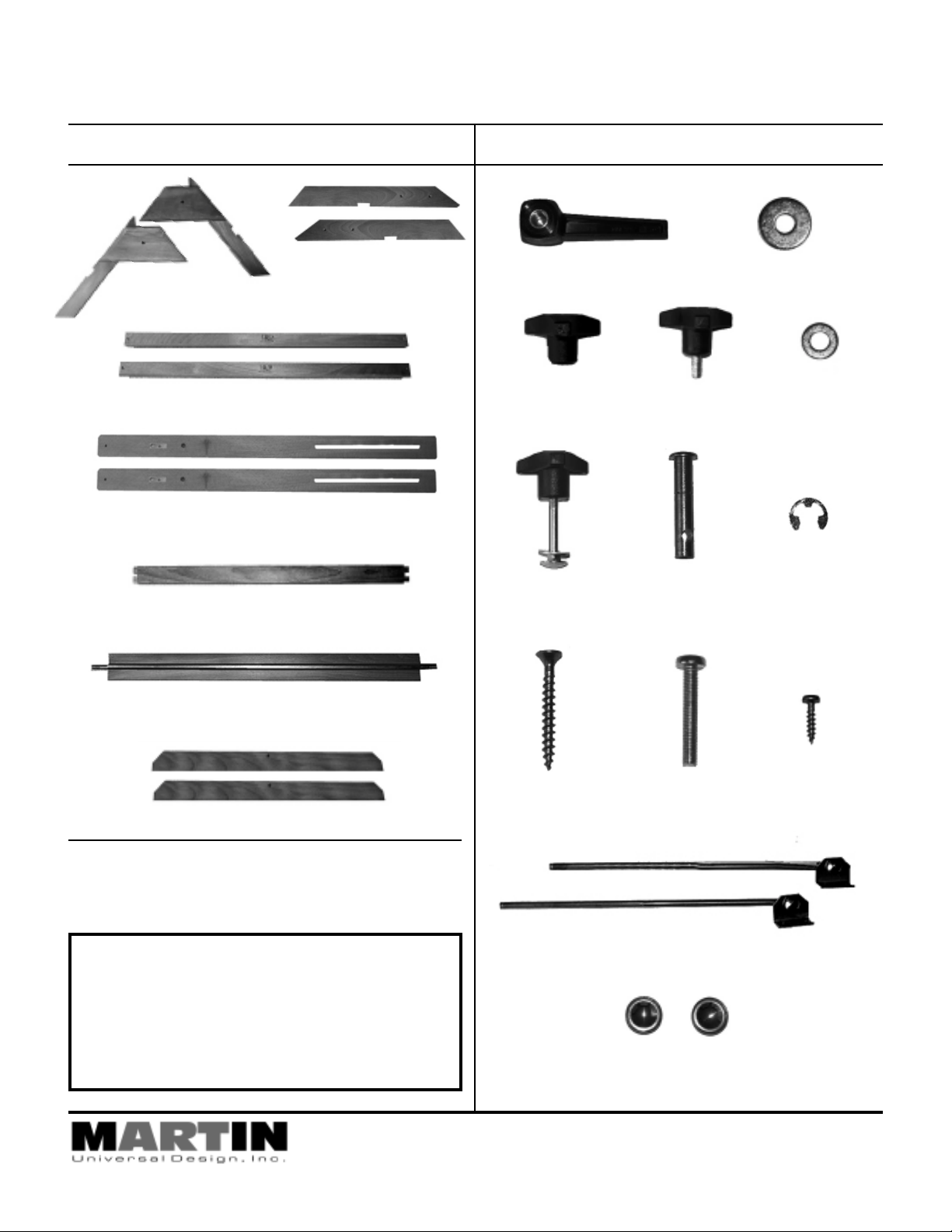
Contents of Carton: Contents of Parts Bag:
[2] Left & Right Legs
for A-Base [B]
[2] A-Base Ends [A]
[2] A-Base Cross Supports [C]
[2] Chanelled Side Supports [D]
[1] Upper Cross ESupport [E]
[1] Chanelled Cross Member with Threaded Rod [F]
[1] ThreadedLever [AA] [1] Large Washer for Lever
[1] Female Knob
[CC]
[2] Female Knobs
with bolt & washer
included [FF]
[2] Male Knob [DD] [1] Washer for
[2] Large Pin with
hole [EE]
[BB]
Female Knob
[2] “C” Washers for
Large Pins
[FF]
[EE]
[2] Drawing Top Braces [G]
Tools needed for assembly:
Phillips Screwdriver, Flat Screwdriver
or Power Drill and Hammer (to tap holes into
drawing board during attachment)
IMPORTANT
If you have difficulty assembling your U-7100 Avanti Base
or need customer service assistance.
Please call: Martin Universal Design, Inc.
Customer Service Hot Line at
1-313-895-0700. If you need additional parts, it is not
necessary to contact your dealer, our Customer Service
Rep. will forward them to you immediately.
4444 Lawton Avenue, Detroit, MI 48208 USA • Tel:(313)895-0700/Fax:(313)895-0709
Email: Custservmud@aol.com • visit us at www.MartinUniversalDesign.com
[12] Long Wood
Screws [GG]
[2] Metal Tilt Adjustment Rods [JJ]
[2] Metal Pin End Caps for Tilt Rods [KK]
[2] 1-3/4” Bolts
[HH]
[4] Small Wood
Screws [II]
Page 2
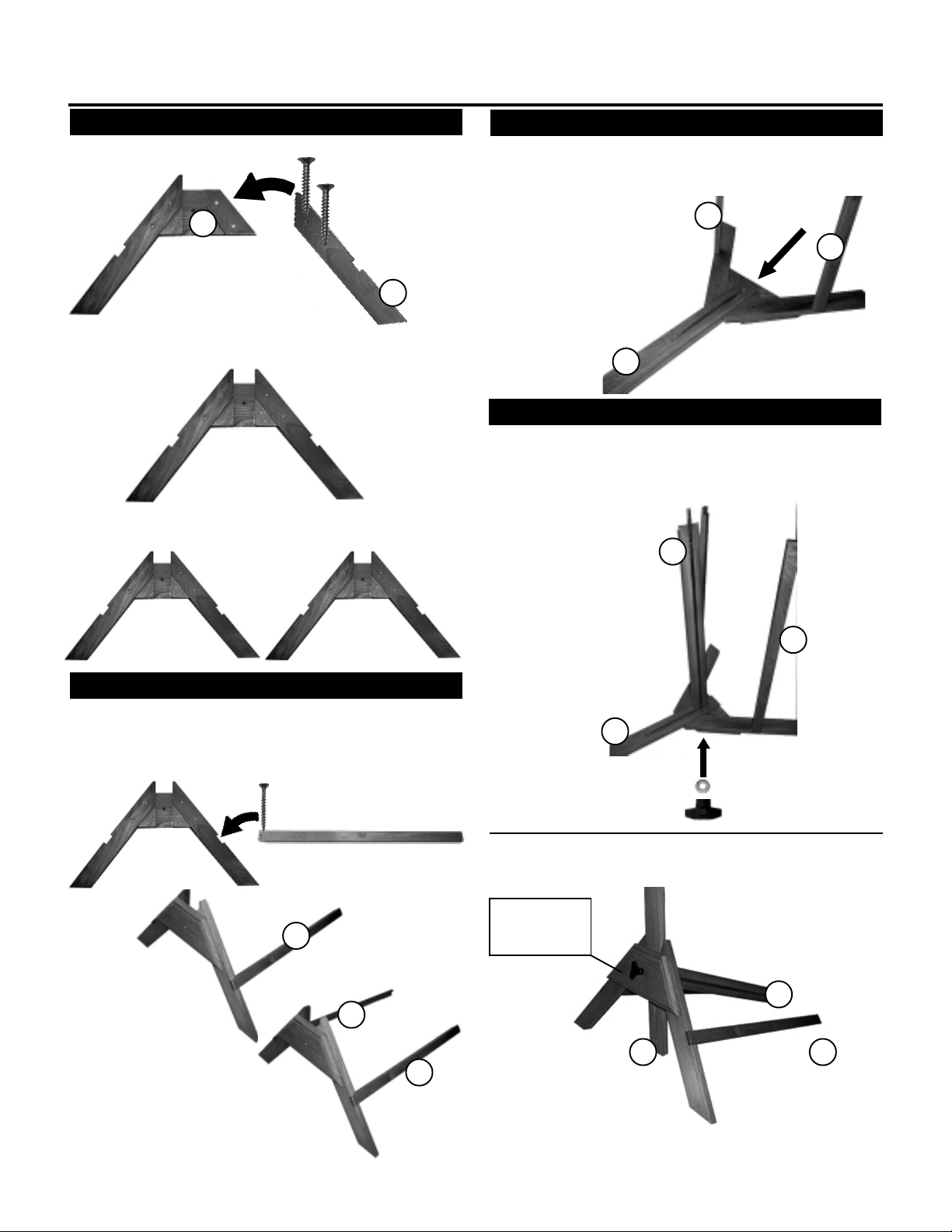
Assembly Instructions:
STEP 1] Assembling A-Base(s)
T ake the A-Base end [A] as shown below and the Left Leg [B]
for the A-Base.
Long Wood
Screws [GG]
A
A-Base end [A]
Position the Left Leg [B] onto the A-Base, lining up holes.
Secure with [2] Long Wood Screws. Tighten. See below for
proper assembly .
Repeat with other side.
Now, you should have [2] complete A-Base Assemblies.
Left Leg [B]
B
STEP 3] Attaching Channelled Side
T ake A-Base end that has the two supports attached and place
on flat surface. Position Channelled Side Support [D] into
middle section of A-Base. Making sure channel is on bottom
end. As shown below.
C
C
D
STEP 4] Adding Lower Support & Rod
With above assembly still laying flat on surface, insert one
end of Channeled Cross Member with Threaded Rod [F] into
Channelled Side Support [D] making sure rod end goes through
other end of A-base assembly . Secure with Washer [EE] and
Female Knob [CC]
F
STEP 2] Attaching A-Base Supports
T ake one assembled A-Base end and attach [1] support bar
(with Logo reading up in correct position) and place into notch
and secure with [1] long wood screw [GG]. See below for
proper assembly.
A-Base Cross Supports [C]
A-Base Assembly
C
Proper assembly of
A-Base & support.
C
C
C
D
After securing with washer [EE] and Female Knob [CC],
turn assembly up onto base as shown below.
Washer [EE]
and Female
Knob [CC]
F
D
C
Repeat with other support.
Attach as shown to right.
Page 3

Assembly Instructions continued:
STEP 5] Securing Lower Support & Rod
Repeat with other A-Base assembly on other side.
First by sliding Channelled Side Support [D] down into A-Base
assembly, then continue by inserting Lower Support & Rod
[F] into Channel in Side Support [D] making sure threaded
rod goes all the way through A-Base assembly , this time
securing with large washer [BB] and Lever [AA]. See photos
below.
D
F
C
Close-up photo of
Lever and large
Washer.
STEP 6] Attaching Upper Cross Support
Take Upper Cross Support [E] and insert one end into small
slot in upper portion of the Channelled Side Support [D].
Secure with 1-3/4” Bolt [HH]. Tighten with Phillips Screwdriver .
Insert other end into other side of Channelled Side Support
[D]. Secure with other 1-3/4” Bolt [HH]. PLEASE NOTE: Y ou
may have to loosen Lever to allow Side Support to pull away
enough to allow end of Upper Cross Support [E] to be inserted into slot. Retighten Lever once completing Step 6.
STEP 7] Inserting Pin into Side Support
Take the [2] Large Pins with Hole [EE] and insert each one
into the hole which is below cross support bolt. Insert pin
through inside of base and through other side as shown below. Secure pin [EE] with “C” Washer by sliding “C” washer
over and onto Pin slot which is located right where Pin and
Side Support meet. PLEASE NOTE: This is difficult to
accomplish. Y ou must use a flat screwdriver to push “C” washer
into slot.
STEP 8] Attaching Tilt Adjustment Rods
Take [1] of the Metal Tilt Adjustment Rods [JJ] and insert it
into the hole in the Pin [EE]. Secure with Metal Pin End Cap
[KK]. Repeat with other side.
KK
Close-up photo of
1-3/4” Bolt attachment.
After Steps 1 - 6.
Base should look like
photo to right.
D
D
JJ
EE
E
STEP 9] Securing Tilt Adjustment Rods
Take [1] Male Knob [DD] and attach to Pin end. Screw in to
tighten. Repeat with other Adjustment Rod.
F
E
C
D
F
DD
C
Page 4

Assembly Instructions continued:
STEP 10] Attaching T op Braces
When attaching the [2] Drawing T op Braces [G], position the
drawing board brace in the position shown here:
Attach to the inside of the Side Support [D] using the [2]
remaining knobs, washers and bolts [F]. Insert bolt through
hole on inside of Drawing top Brace, making sure bolt goes
through side support [D]. Finish by attaching washer and then
female knob.
F
G
D
PLEASE NOTE:
Correct attachment of Drawing Top Braces will have
large holes on Drawing Top Brace facing downward.
Before securing base of table to 30” x 42” Drawing Board top, you
must center the base to the top.
Rear Edge of Top
Front Edge of Top
Center base by measuring 7” in [Measurement Y] from outside
edges of Drawing Board to outside edge of Base Braces and
5-1/8” in from front edge of drawing board to front edge of Base
Brace and 5-1/8” in from rear edge of drawing board to rear
edge of base Brace. See illustration below. Secure using [4]
Long Wood Screws [GG] per Base brace. This top is 30” x 42”.
Y = 7”
Y = 7”
Attach
Bracket on
Tilt
Adjustment
Rods into
Top
STEP 1 1] T urning Base over
PLEASE NOTE: BEFORE TURNING BASE OVER
ONTO DRAWING BOARD: MAKE SURE DRAWING
BOARD BRACES ARE IN A HORIZONT AL
POSITION AND KNOBS ARE TIGHTENED.
Use two people with this next step. Lay top on carpeted flat surface.
Carefully turn completed base assembly up and over and place
on top of bottom side of drawing board.
PLEASE NOTE: Both sides of Drawing board can be the bottom
side. Choose best looking for Top Side.
STEP 12] Attaching Base to Drawing T op
Base should look and be positioned to Drawing Board as
pictured below.
X = 5-1/8”
X = 5-1/8”
STEP 13] Attaching Tilt Adjustment Rods
to Drawing Board
Attach metal tilting brackets to top using [2] each small wood
screws [II] per bracket as shown above. PLEASE NOTE: Break
Table Top Surface by making a small hole in top surface where
screw will go in with hammer and a nail.
STEP 14] T able T op Tilt Adjustments
To make your table top tilt: Loosen the [2] black knobs (with
tilt rods through them), proceed by holding onto the front
edge of the top. Tilt top until desired position is reached.
Tighten [2] black plastic knobs.
STEP 15] T able Height Adjustment
T o adjust the height of your table, loosen the lever slightly.
PLEASE NOTE: When loosening the lever, the table
will want to lower because of the weight of the top.
Carefully, loosen lever and support table top with
hands and lower or raise until desired height. Retighten Lever to secure. This adjustment is safest with
another adult helping.
4444 Lawton Avenue, Detroit, MI 48208 USA • Tel:(313)895-0700/Fax:(313)895-0709
Email: Custservmud@aol.com • visit us at www.MartinUniversalDesign.com
 Loading...