

Page 1
U-145N • Avanti Master Studio Art Easel
ASSEMBLY INSTRUCTIONS
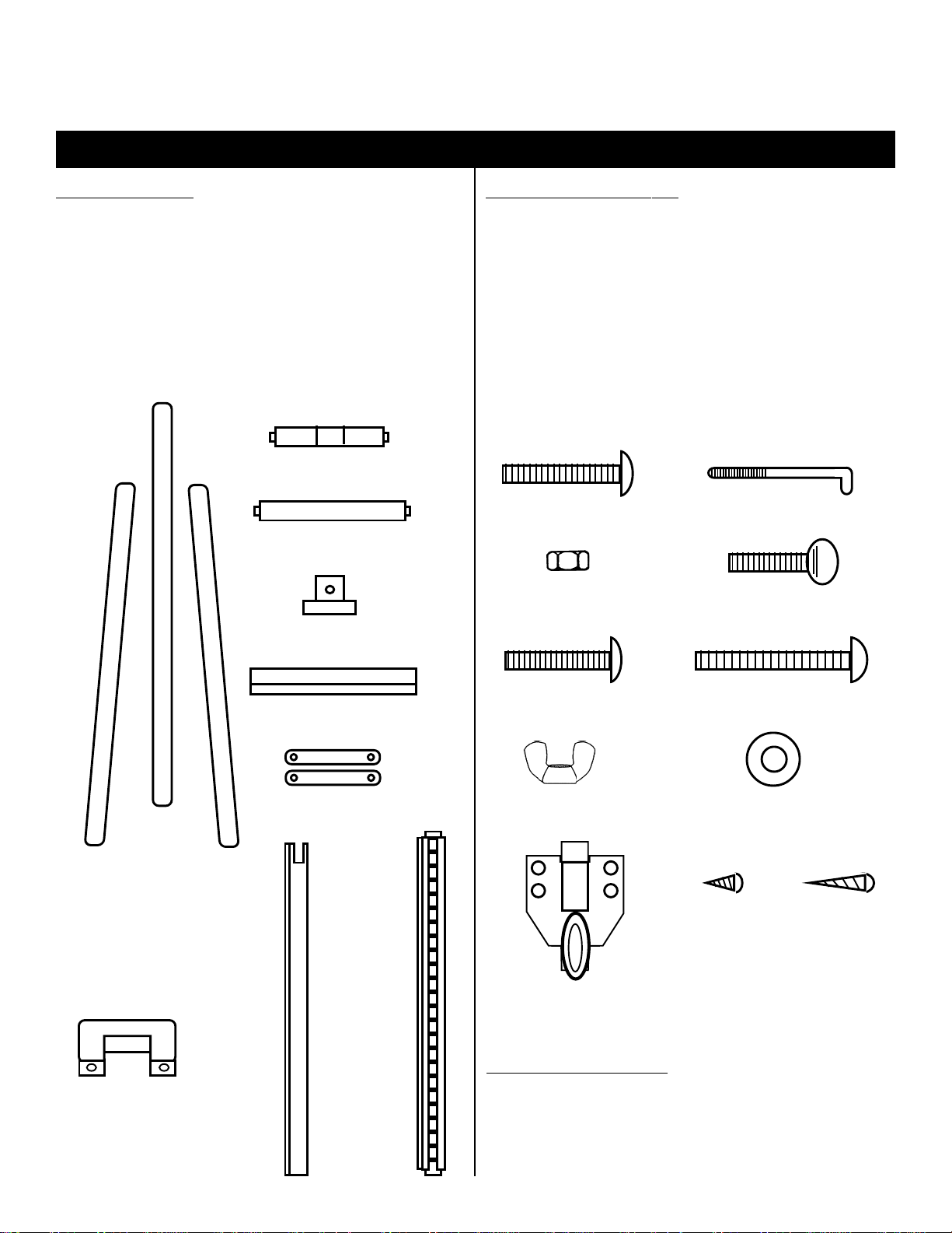
MAKE SURE CARTON CONTAINS THE FOLLOWING PARTS
WOOD PARTS
Quantity ........Description ID#
2 ea. .......Side Legs ( 1 Left & 1 Right) [A]
1 ea. .......Center Mast Column [B]
1 ea. .......Rear Spike Leg [C]
1 ea. .......Metal/Wood Ratchet Co lumn [D]
1 ea. .......Upper Cross Member [E]
1 ea. .......Lower Cross Member [F]
1 ea. .......Upper Canvas Support [G]
1 ea. .......Lower Canvas Support [H]
2 ea. .......Wood Angle Brackets [J]
1 ea. .......Lower Canvas Support Bracket [K]
Upper Cross member
[E]
Lower Cross member
[F]
Upper Canvas Support
[G]
HARDWARE PARTS
Quantity ........Description ID#
4 ea. .......2-1/4” Bolts [L]
2 ea. .......“L” Threaded Bolts [M]
2 ea. .......Hex Nuts [N]
1 ea. .......Wing Bolt [O]
1 ea. .......2-1/8” Bolt [P]
2 ea. .......3” Bolts [Q]
3 ea. .......Wing Nuts [R]
3 ea. .......Washers [S]
1 ea. .......Loop Mechanism [T]
2 ea. .......Small screws [U]
2 ea. .......Long Screws [V]
2-1/4” Bolts
[L]
Hex Nuts
[N]
Threaded “L” Bolts
[M]
Wing Bolt
[O]
Left Side Leg
[B]
“U” Bracket for
Lower Canvas
Support [K]
Center Mast
Column [A]
Right Side Leg
[B]
Rear Spike
Leg [C]
Lower Canvas Support
[H]
Wood Angle
Brackets
[J]
Metal/Wood
Ratchet Column
[D]
2-1/8” Bolts
[P]
Wing Nuts
[R]
Small Screws
Loop Mechanism
[T]
3” Bolts
[Q]
Washers
[S]
Long Screws
[U]
TOOLS INCLUDED
Quantity ........Description ID#
1 ea. .......Flat Wrench [W]
1 ea. .......Screwdriver [X ]
[V]
Page 1
Page 2
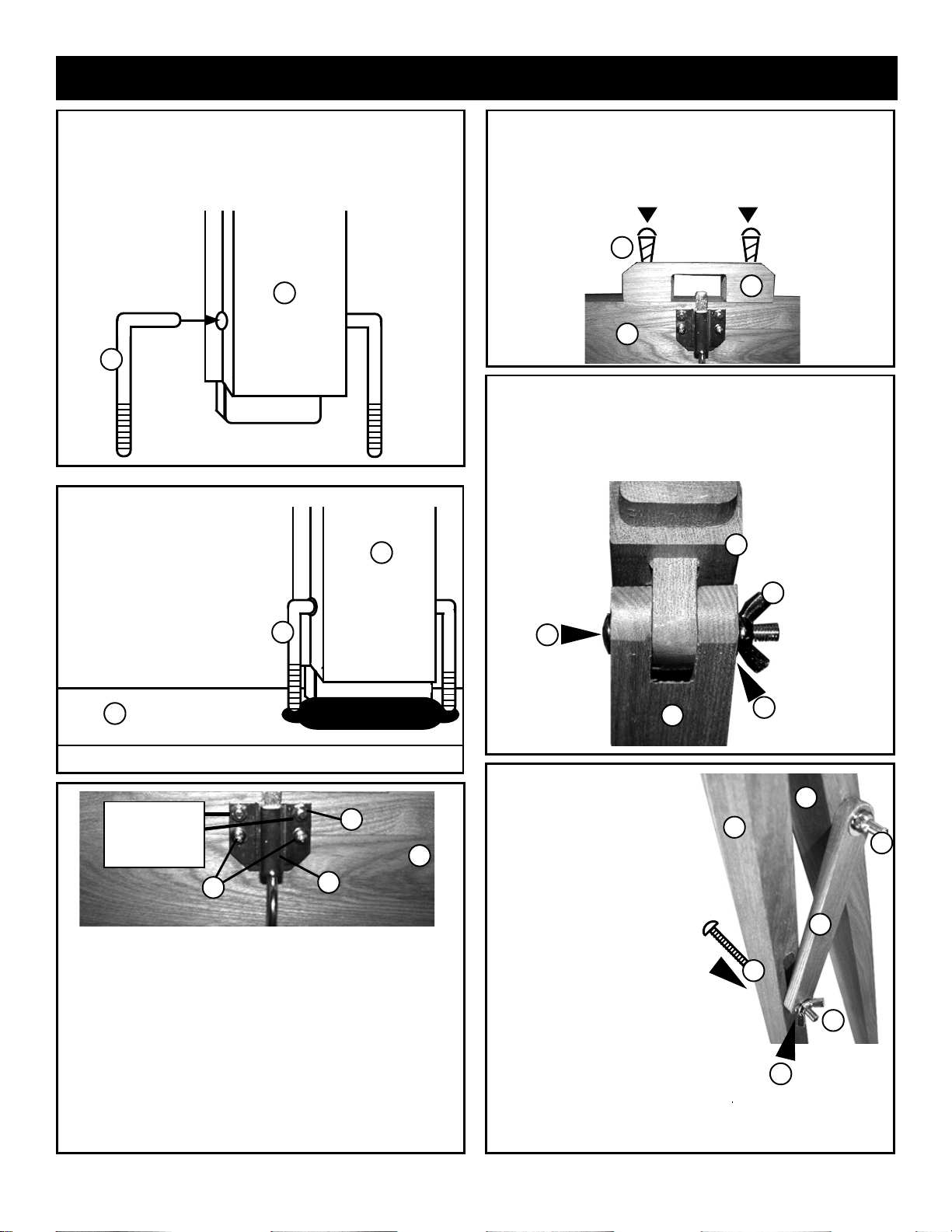
For recommended assembly lay all wood parts on flat surface with all holes facing up.
STEP 1. Attach lower canvas support [H] to center mast
column [A] using the 2 ea. “L” Bolt [M] provided.
First insert the shorter end of the “ L” Bolt into the holes on
the sides of the center mast column [A].
A
M
FIG 1
STEP 2. Then proceed to
insert the long ends of the “L”
brackets [M] down into the oval
hole lining up the center mast
A
notch with the lower canvas
support oval hole.
SEE FIG 2.
M
STEP 4. Attach “U” bracket [K] to rear of lower canvas
support [H] by using 2 ea. Long screws [V]. Secure
using screwdriver provided. See FIG . 4
V
K
H
STEP 5. Attach Rear Spike Leg [C] to Met al/W ood
Ratchet Column [D] by lining up notch and joiner, continue
by inserting a 2-1/8” bolt [P] through all holes and secure
with Washer [S] and Wing Nut [R]. See FIG 5 below .
D
R
P
Top edge of lower
H
canvas support
with oval hole
FIG 2
Top holes for
threaded ends
of “L” bolts
and hex nuts.
U
N
H
T
FIG 3
STEP 3. Attach Metal Loop Mechanism [T] to bottom of
Lower canvas support [H] making sure the two threaded
ends of the “L” bolts [M] go through the top two holes of
the Loop Mechanism [S]. Secure by attaching the 2 ea.
Hex Nuts [N] to the threaded ends of the “L” Brackets.
Tighten the Hex Nuts [N] by using the flat wrench
supplied. Secure by screwing in 2 ea. Small screws [U]
into lower holes below Hex Nuts. See FIG 3 illustration
for location.
C
STEP 6. Attach 2 ea. Wood
Brackets [J] to Ratchet/Center
Column assembly by inserting
a 3” bolt [Q] through one hole
C
of wood bracket and continue
by inserting bolt through
Ratchet Column and Rear
Spike Leg. Continue through
other side while attaching
another wood bracket. Secure
with Washer [S] and Wing Nut
Q
[R].
PLEASE NOTE: Bolt is to go
through slot on Center
Column. Repeat with other 3”
bolt for remaining hole.
NOTE: These Wing Nuts will be used
for the tilt adjustment of the easel
once assembled by loosening and
then re-tightening at desired angle.
S
FIG 5
D
R
J
R
S
FIG 6
Page 2
Page 3

STEP 7. Attach lower cross member [F] to left leg [B]
and right leg [B] by lining up the angled joiner on the cross
member to the slotted holes in the legs. Secure by using
the 2 ea. 2-1/4” Bolt [L] and screw in with screwdriver
provided. Making sure oval hole is positioned on top edge
of cross member. See FIG 7 & 7B
B
FIG 7
F
STEP 10. Attach Upper Cross Member [E] by sliding it
over the top of the Center mast Column [A] and continue
sliding it down along the channels. PLEASE NOTE:
Make sure that you have the Upper Cross Member in the
correct position, by making sure the oval hole is on the
bottom edge. See FIG . 10.
L
F
B
FIG 7B
B
STEP 8. Attach Ratchet/Center Column assembly by
inserting the lower end of the Ratchet Column through the
Lower Canvas Support “U” Bracket [K].
Please Note: When inserting the ratchet assembly ,
proceed to push through until you hear the ratchet
“CLICK” into place. See FIG 8.
K
D
C
A
E
oval hole
positioned here.
FIG 10
STEP 1 1. Continue sliding Upper Cross Member [E]
downward along channel until you reach the top end of the
Ratchet Column [D]. Insert notched end into oval hole in
Upper Cross Member [E]. See FIG . 11.
A
D
E
H
FIG 8
STEP 9. Attach Ratchet/Center Column assembly to
Lower Cross Member [F] by inserting notched end of
ratchet column into oval hole in the top edge of the cross
member. See FIG 9.
B
F
B
FIG 9
FIG 11
STEP 12. Secure Upper Cross Member by using the 2
remaining 2-1/4” Bolts [L] into the holes that are on the
outside edge of Legs [B] near the top. Tighten with
screwdriver supplied. PLEASE NOTE: Make sure bolt
goes through and into Cross Member too.
See FIG 12.
B
A
B
E
Tighten with
screwdriver
FIG 12
Page 3
Page 4

STEP 13. Attach Upper Canvas Support [G] to Easel by
sliding it downward from the top of the Center Column [A]
gliding it along the channel.
Secure at desired height by screwing in Wing Bolt [O] in
hole on front of Upper Canvas Support [G]. See FIG 13.
PLEASE NOTE: Loosen Wing bolt to move Upper
Canvas Support to desired position whenever
needed. Tighten Wing Bolt to secure.
A
O
G
FIG 13
STEP 14. Adjusting height Lower Canvas Support.
Insert finger in locking pin below Lower Canvas Support
and pull outward. This will cause the canvas support to
release from the metal ratchet column allowing you to raise
or lower the lower canvas support and center column.
PLEASE NOTE: Be careful when raising the canvas
support, that you are aware that the top of the
column will not interfere with ceiling or any other
object in rooms that have low ceilings.
FIG 14
Easel should look like photo to right.
Angle Adjustment:
Loosen wing nut on rear leg and tighten at desired angle.
Height Adjustment:
Unlock locking pin on lower canvas support, adjust to
desired height and release locking pin.
Enjoy your Easel!
If you have any problems with assembling this
easel, please call (313)895-0700 or e-mail us at
Custservmud@aol.com.
Thank Y ou.
Martin/F. Weber Co. • 4444 Lawton Avenue, Detroit, MI 48208 USA
Tel:(313)895-0700 • Fax:(313)895-0709 • E-mail:Custservmud@aol.com
www.MartinUniversalDesign.com • www.weberart.com
Made in China
MUD021006
Page 4
 Loading...